Table of Contents
Advertisement
These instructions are intended for use only by experienced, qualified
combustion start-up personnel. Adjustment of this equipment and its
components, by unqualified personnel, can result in fire, explosion, severe
personal injury, or even death.
Table of Contents
Subject
General Information ....................................................................
Receiving and Inspection..............................................................
Installation.................................................................................
Adjustments and Final Checkout....................................................
Electronic Valve Characterization...................................................
Operation..................................................................................
Troubleshooting..........................................................................
Appendix A: Operator Interface Screens.........................................
Appendix B: Configuration Record.................................................
Appendix C: Recommended Spare Parts........................................
Appendix D: DL250 Programmable Controller..................................
Appendix E: High Temperature Limit..............................................
Appendix F: Exhaust Fan Flow Limit Installation...............................
Appendix G: Stack Thermocouple Installation..................................
Appendix H: Material Thermocouple Installation...............................
Appendix K: Auxiliary Analog Input .......................................................
Attachments: Applicable Hauck Drawings
These instructions are intended to serve as guidelines covering the installation, operation, and maintenance of Hauck equipment. While
every attempt has been made to ensure completeness, unforeseen or unspecified applications, details, and variations may preclude
covering every possible contingency. WARNING: TO PREVENT THE POSSIBILITY OF SERIOUS BODILY INJURY, DO NOT USE OR
OPERATE ANY EQUIPMENT OR COMPONENT WITH ANY PARTS REMOVED OR ANY PARTS NOT APPROVED BY THE
MANUFACTURER. Should further information be required or desired or should particular problems arise which are not covered
sufficiently for the purchaser's purpose, contact Hauck Mfg. Co.
HAUCK MANUFACTURING CO.,
3/14
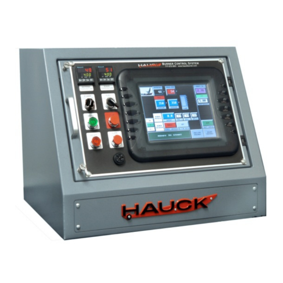
BCS 6000C
BURNER CONTROL SYSTEM
Draft Transmitter Adjustments.....................................
.......................................................
100 North Harris Street Cleona, PA 17042 717-272-3051
www.hauckburner.com
WARNING
Fax: 717-273-9882
INSTRUCTIONS
Page
2
3
3
5
9
11
13
16
20
21
22
24
27
28
29
31
33
38
39
BCS-6000C-9
Advertisement
Table of Contents

Subscribe to Our Youtube Channel
Summary of Contents for Hauck BCS 6000C
-
Page 1: Table Of Contents
…............ Attachments: Applicable Hauck Drawings These instructions are intended to serve as guidelines covering the installation, operation, and maintenance of Hauck equipment. While every attempt has been made to ensure completeness, unforeseen or unspecified applications, details, and variations may preclude covering every possible contingency. -
Page 2: General Information
Annual review and upgrading of safety equipment is recommended. A. GENERAL INFORMATION The Hauck Burner Control System (BCS) provides burner management and temperature control of a single pilot ignited burner firing on natural gas, oil, or liquid propane (LP). The spark ignited, gas fired pilot is interrupted after the main burner flame has been established. -
Page 3: Receiving And Inspection
For optimum use of the BCS panel, it is suggested that the drawings provided by Hauck be referred to for limit switch and valve installation, and wiring. In the event that a recommended switch or valve is not used, it may be necessary to connect jumper wire(s) between appropriate terminals in the control panel or burner junction box. - Page 4 Install the stack temperature thermocouple in the dryer exhaust duct to sense exhaust gas temperature. See Appendix G. for installation instructions. Install a Hauck Rapid Response material temperature thermocouple in the material discharge chute to sense the temperature of the material leaving the dryer. See Appendix H.
-
Page 5: Adjustments And Final Checkout
Page 5 BCS6000C-9 Be sure that all equipment and components have been installed in accordance with the manufacturer's instructions. Verify the positions of the FUEL SELECT, AIR SELECT, and AUX SELECT switches on the printed circuit board. The switches must be set to be compatible with the burner control motor(s). - Page 6 Page 6 BCS6000C-9 MOTOR CALIBRATION The control motor DEADBAND settings determine the allowable deviation of actual control motor position from setpoint without corrective action by the motor control outputs (minimum 0.5%, maximum 5.0%, typically set at 1.0%). These parameters should be set as low as possible without causing the control motors to ‘hunt’...
- Page 7 10% and calculate new gain and reset values based on the process response. Auto Tune will be complete after the associated temperature has increased by approximately 40 F (4°C). Consult Hauck’s Service department if a larger or smaller ° step is required.
- Page 8 Page 8 BCS6000C-9 To accommodate variations in material moisture or composition and prevent nuisance shutdowns, provisions are made for automatic draft setpoint increase. The PLC senses ‘puffs’ in the dryer drum and automatically increases dryer draft if a set number of ‘puffs’ occurs within a ten second time window.
-
Page 9: Electronic Valve Characterization
Page 9 BCS6000C-9 E. ELECTRONIC VALVE CHARACTERIZATION WARNING Adjustment of this equipment by unqualified personnel can result in fire, explosion, severe personal injury, or even death. This procedure requires the use of a stack analyzer to properly adjust air/fuel ratio and optimize burner performance. It is intended for qualified personnel, familiar with combustion systems and the interpretation of stack emission readings. - Page 10 Page 10 BCS6000C-9 BIAS POINT ADJUSTMENT Bias adjusting screens are accessed via the MAIN MENU. Before firing the burner, verify the OIL FIRING BIAS POINTS and GAS FIRING BIAS POINTS are set to the default values listed below. Point Oil/LP Light off Low Fire 10.0...
-
Page 11: Operation
Page 11 BCS6000C-9 F. PANEL OPERATION 1. Open all manual shutoff valves to supply air and fuel to the pilot and burner systems. 2. Move the panel POWER switch to ON and verify that the FUEL SELECTOR switch is in the desired position. - Page 12 Page 12 BCS6000C-9 c. A ten second main flame trial for ignition time will begin. d. A ‘MAIN FLAME TRIAL FOR IGNITION’ message will be displayed. 12. After the trial for ignition time has been completed: a. The pilot solenoid valves will be de-energized and the pilot will go out. b.
-
Page 13: Troubleshooting
Page 13 BCS6000C-9 G. TROUBLESHOOTING Use the HELP screens on the touch screen or refer to the following table. MESSAGE DIAGNOSTICS The difference between the Zero and Span feedback values of each CONTROL MOTOR CALIBRATION motor must be greater than 3300. Verify that the motors travel full REQUIRED stroke during the motor calibration procedure. - Page 14 EZTouch Hardware User Manual for battery replacement instructions. Indicates low PLC battery voltage. The battery compartment is REPLACE PLC BATTERY located in the CPU. A replacement battery is available from Hauck (Part No. 62311) or Automation Direct (Part No. D2-BAT-1).
- Page 15 Page 15 BCS6000C-9 ALARM HISTORY Screen An alarm history screen is also provided for use as a troubleshooting guide. From the MAIN MENU screen press ALARM HISTORY to view a list of the last 99 logged events and the order in which they occurred.
-
Page 16: Appendix A: Operator Interface Screens
Page 16 BCS6000C-9 APPENDIX A: OPERATOR INTERFACE SCREENS MAIN SCREEN This screen displays overall system status and is the default screen on system power-up. It provides AUTO/MANUAL control selection and setpoint inputs for the temperature control loops. Note that the message box in the lower left corner of the screen appears on all screens to provide the operator with system status messages. - Page 17 Page 17 BCS6000C-9 MOTOR CALIBRATION & SETUP Reference Section E. Used to ZERO and SPAN the burner control motors and to enter motor deadband settings. Provides numeric inputs for burner firing rate limits, gas pressure correction, and temperature bias settings. CONTROL LOOP TUNING Reference Section E.
- Page 18 Page 18 BCS6000C-9 RUN MENU Reference Section E. Used to set the burner startup percentage and ramp rate for automatic temperature control. Also provides for low fire drive alarms and draft setpoint inputs, selection of control mode and parameters for automatic draft increase control. BIAS POINT SETTINGS Reference Section F.
- Page 19 Page 19 BCS6000C-9 TRENDS Four separate trend screens provide 5 minute, 15 minute, 4 hour and 8 hour trends of Material temperature; Stack temperature, Setpoint and burner firing rate.
-
Page 20: Appendix B: Configuration Record
Page 20 BCS6000C-9 APPENDIX B: CONFIGURATION RECORD Factory set default values are shown in parenthesis, e.g.,(1.0) MAIN MENU SCREEN PLC PROGRAM: __________ SCREEN PROGRAM: __________ MOTOR CALIBRATION & SETUP SCREEN MOTOR ZERO SPAN DEADBAND (1.0) (1.0) (1.0) BURNER OUTPUT LIMIT: (100.0)__________ GAS PRESSURE: (24.0) __________ oz. -
Page 21: Appendix C: Recommended Spare Parts
Page 21 BCS6000C-9 APPENDIX C: RECOMMENDED SPARE PARTS PART DESCRIPTION 302263 Flame relay, UV 56650 Amplifier, UV Flame Relay 20579 Scanner, UV 58485 Relay, SPDT, 120Vac 17292 Relay, 3PDT, 120Vac 46311 Relay, Solid State w/6.8k Resistor 61961 Timer, DPDT Purge 61818 Power Supply, 24Vdc, 1.2A 53763... -
Page 22: Appendix D: Dl250 Programmable Controller
Page 22 BCS6000C-9 APPENDIX D: DL250 PROGRAMMABLE CONTROLLER BASE: 9-Slot Base w/8 I/O Modules. Part No. 58484 CPU: Central Processing Unit. Part No. 400429 BATTERY: CPU 3V Battery. Part No. 62311 SLOT 0: 8-Point Analog Voltage Input Module. Part No. 63319 Input Wire Function... - Page 23 Page 23 BCS6000C-9 SLOT 3 cont. Input Wire Function Opt switch Spare AC Neutral SLOT 4: 8-Point Relay Output Module. Part No. 58479 Output Wire Function Purge relay, R2 Run relay, R3 Pilot scanner relay, R4 Pilot relay, R5 Gas motor increase relay, R6 Gas motor decrease relay, R7 Air motor increase relay, R8 Air motor decrease relay, R9...
-
Page 24: Appendix E: High Temperature Limit
Page 24 BCS6000C-9 APPENDIX E: HIGH TEMPERATURE LIMIT Two high temperature limit instruments (P/N 402731) are provided for temperature indication and over-temperature protection. Each instrument receives a thermocouple input and provides a 0 to 5Vdc temperature signal to the PLC. The thermocouple of the MATERIAL CONTROL instrument is positioned to read the temperature of the material as it exits the dryer while the STACK TEMPERATURE instrument’s thermocouple senses the temperature of the exhaust gases. - Page 25 Page 25 BCS6000C-9 CONFIGURATION °F The instruments are factory set for a type J thermocouple with a range of 32 to 842 Use the following procedure to change thermocouple type or temperature units if required. Detailed information is given in the vendor literature supplied with the control panel. Press and hold the SETUP key then press the ▲...
- Page 26 Page 26 BCS6000C-9 CHANGING THE SET POINT Press and hold the SETUP key then press the ▲ arrow key. OPtr will appear in the Upper Display. Release the SETUP key and press the ▲ arrow key until the Upper Display reads SEtP, then press SETUP.
-
Page 27: Appendix F: Exhaust Fan Flow Limit Installation
Page 27 BCS6000C-9 APPENDIX F: EXHAUST FAN FLOW LIMIT SWITCH INSTALLATION Mount the exhaust fan flow switch in the dryer exhaust duct as shown in Figure 1. Y6909 (NOT TO SCALE) Figure 1. Installation of Exhaust Fan Flow Switch Wire the exhaust flow switch to the appropriate terminals. The exhaust flow switch is an interlock, which requires the exhauster to be operating prior to ignition of the burner. -
Page 28: Appendix G: Stack Thermocouple Installation
Page 28 BCS6000C-9 APPENDIX G: STACK THERMOCOUPLE INSTALLATION Install a Hauck stack temperature thermocouple in the dryer exhaust duct to sense exhaust gas temperatures as shown in Figure 1. X7617 (NOT TO SCALE) Figure 1. Installation of Thermocouple in Exhaust Duct... -
Page 29: Appendix H: Material Thermocouple Installation
BCS6000C-9 APPENDIX H: MATERIAL THERMOCOUPLE INSTALLATION Install a Hauck Rapid Response Material Temperature Thermocouple in the material discharge chute to sense the temperature of the material leaving the dryer as shown Figure 1. Wire the thermocouple to the proper terminals in the panel. - Page 30 Page 30 BCS6000C-9 NOTE During normal operation, the thermocouple should be rotated once a month to expose a different area of its surface to the abrasive forces of the material. This procedure will increase the effective life of the thermocouple. If excessive wear occurs, a protective tube may be added to shield the shaft in the region of the high velocity flow.
-
Page 31: Appendix I: Draft Transmitter Adjustments
Page 31 BCS6000C-9 APPENDIX I: DRAFT TRANSMITTER ADJUSTMENTS The NEXT and ENTER buttons located below the LCD display may be used to adjust or reconfigure the draft transmitter if required. Wait one or two seconds between each button press to allow the display to update. ZEROING Allow the unit to warm up for at least five minutes before adjusting the transmitter zero. - Page 32 Page 32 BCS6000C-9 calibration changes can be discarded by pressing ENTER when the lower display reads CANCEL instead of SAVE. 4 MA ADJUSTMENT Verify that when the transmitter reads 0.00, the BCS 6000 touchscreen display also reads 0.00. If necessary, adjust the transmitter 4 mA value using the following procedure. ...
-
Page 33: Appendix J: Flame Supervision And Safety Component Check List
Equipment: Multi-meter capable of measuring Continuity and AC voltage (120Vac) System Schematic CAUTION The BCS 6000C control panel power must be on to perform the following checks. Avoid contacting exposed wiring and terminals when checking voltage or continuity and after removing the pressure switch covers to make adjustments. - Page 34 Page 34 BCS6000C-9 Restart the primary air blower. Shut off the secondary air blower. Continuity should disappear between terminals 13 and 14 immediately, but should remain between terminals 14 and 16 for several seconds as the secondary air blower coasts to a stop. ATOMIZING AIR LIMITS (EcoStar II or MegaStar with primary air blower for Oil or LP fired systems only) ...
- Page 35 Page 35 BCS6000C-9 Close the manual valve in the main gas line to shut off the gas supply. The burner should shut off, the alarm will sound, and a ‘LOW GAS PRESSURE’ message should appear. HIGH GAS PRESSURE (Gas-fired systems only) ...
- Page 36 Page 36 BCS6000C-9 value, then press the RESET key on the STACK instrument to reset the fault and extinguish the OUT indicator. FLAME FAILURE TEST Start the burner and establish the low fire burner flame. Simulate flame failure by closing the manual shutoff valve downstream of the safety shutoff valves, or as an alternative to closing the manual valve system, temporarily disconnect field wire 87 from the control panel terminal strip.
- Page 37 Page 37 BCS6000C-9 to fill the pipe between Safety Shutoff Valve No. 2 and the manual shutoff valve. Connect the tubing to Leak Test Valve No. 2 and immerse the open end in water as before. Open Test Valve No. 2. If bubbles appear, record the leakage rate in bubbles/min and refer to the IMPORTANT note at the end of this section.
-
Page 38: Appendix K: Auxiliary Analog Input
CAUTION: Interaction between power sources and/or supplies can interfere with the analog signals of the BCS 6000 control system. Therefore, a Signal Isolator (Hauck part number 62715) is recommended for any input signal that is not powered by the BCS 6000 panel. The output of the isolator should be set for 0-5Vdc. -
Page 39: Appendix L: Optimizer Operation
Page 39 BCS6000C-9 APPENDIX L: OPTIMIZER OPERATION Some systems are configured to include special provisions for fuel optimization. This feature enables firing gas as the primary fuel along with a secondary (Optimizer) fuel. The percentage of the secondary fuel is adjustable and may be changed while the burner is in operation. NOTE: On burners with a low fire bypass oil valve, a Normally Open Oil Bypass Solenoid valve must be installed. - Page 40 Page 40 BCS6000C-9 This page left intentionally blank.
Need help?
Do you have a question about the BCS 6000C and is the answer not in the manual?
Questions and answers