
Subscribe to Our Youtube Channel
Summary of Contents for Aybey Elektronik AE-LIFT Series
- Page 1 AE-LIFT AE-LIFT AE-LIFT AE-LIFT MOTOR DRIVER MOTOR DRIVER MOTOR DRIVER MOTOR DRIVER USER MANUAL Version: 1.1...
-
Page 2: Table Of Contents
Index SECTION 1-WARNINGS..............................1 SECTION 2-TECHNICAL SPECIFICATIONS.........................2 2.1 ELECTRICAL SPECIFICATIONS..........................2 2.2 MECHANICAL SPECIFICATIONS..........................3 SECTION 3-TECHNICAL SPECIFICATION OF AUXILIARY UNITS..................4 SECTION 4-ELECTRICAL CONNECTIONS and TERMINAL LIST..................6 4.1 MOTOR DRIVER MAIN CONNECTIONS........................6 4.2 DRIVER – MOTOR CONNECTIONS........................7 4.3 CONTROL OF MOTOR CONTACTORS........................8 4.3.1 Control of Motor Contactors by AE-Lift......................8 4.3.2 Control of Motor Contactors by Control Panel...................9 4.4 BRAKE COIL SWITCHING............................9 4.6 CONTROL CIRCUIT TERMINALS..........................10... - Page 3 AE-Lift motor driver. All terminals are pluggable and placed out of the box. No need to open device box for any connection. Some information on this manual may out of date or missing due to system evaluation. You can download the latest version of the manual from our website www.aybey.com. Aybey Elektronik...
-
Page 4: Section 1-Warnings
SECTION 1-WARNINGS Read user manual carefully before installation. • Cut off power (line, UPS or battery) and wait at least 10 minutes before if you have to open • device cover. Connect earth (PE) terminal before power on. • Do not connect or disconnect a terminal when the device power is on. •... -
Page 5: Section 2-Technical Specifications
SECTION 2-TECHNICAL SPECIFICATIONS 2.1 ELECTRICAL SPECIFICATIONS AE-Lift motor driver technical specifications and maximum capacities are listed in Table 2.1. Device can be damaged if loaded more than maximum capacities or installed without proper auxiliary units. For this reason, select device model according to motor current, voltage and other specifications and select other parts in control panel according to values listed in Table 3.1. -
Page 6: Mechanical Specifications
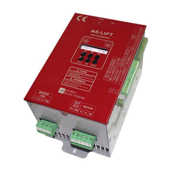
2.2 MECHANICAL SPECIFICATIONS AE-LIFT motor driver box is shown in Figure 2.1. Dimensions are listed in Table 2.2 and box installation holes are shown in Figure 2.2. able 2.2 Mechanical Dimensions Driver Model AEL05 / AEL07 AEL11 AEL15 / AEL22 F/7.5.5.02.95 R:1 AE-LIFT... -
Page 7: Section 3-Technical Specification Of Auxiliary Units
SECTION 3-TECHNICAL SPECIFICATION OF AUXILIARY UNITS Technical informations about power, connection, switching and filter equipments for AE-Lift are listed in Table 3.1. Table 3.1 Technical Information about Part List for AE-LIFT Contactor Selection AEL05 AEL07 AEL11 AEL15 AEL22 Motor Contactors (K1-K2) 18 A 22-25 A 32 A... - Page 8 Rescue Function AEL05 AEL07 AEL11 AEL15 AEL22 UPS-PowerCircuit 1500 VA 2000 VA 3000 VA 4000 VA 5000 VA UPS-Control Circuit 1000 VA 5 x 7Ah 5 x 12Ah Battery-Power Circuit 60V DC 60V DC * Selection of battery, UPS and cable is made according to the parameter of Rescue Direction [C18] is set to EASY DIRECTION.
-
Page 9: Section 4-Electrical Connections And Terminal List
SECTION 4-ELECTRICAL CONNECTIONS and TERMINAL LIST 4.1 MOTOR DRIVER MAIN CONNECTIONS Figure 4.1 AE-LIFT Main Connection Diagram F/7.5.5.02.95 R:1 AE-LIFT... -
Page 10: Driver - Motor Connections
4.2 DRIVER – MOTOR CONNECTIONS Connections of motor contactor are changing according to motor type. Output terminals, contactors and motor connections of induction motor are shown in Figure 4.2; connections of gearless machine are shown in Figure 4.3. Figure 4.2 Induction / Asynchronous Motor (Geared Machine) Connections Figure 4.3 Synchronous Motor (Gearless Machine) Connections Contactor, which has 2 Open –... -
Page 11: Control Of Motor Contactors
4.3 CONTROL OF MOTOR CONTACTORS 4.3.1 Control of Motor Contactors by AE-Lift AE-Lift has hardware and software ability to control motor contactors directly. Control of contactor can be very accurate by contactor release and timing parameters. In Figure 4.4, control panel activates ENB input and AE-Lift motor driver controls the contactors. Due to contactor and ENB signal comes from different sources, synchronization of the control achieved by MCF (Contactor Feedback) function as defined to programmable input I1. -
Page 12: Control Of Motor Contactors By Control Panel
4.3.2 Control of Motor Contactors by Control Panel When switching of contactors is achieved by control panel, use connections in Figure 4.6. In this application, when control panel send motion command, it activates K1 and K2 contactor coils and REN relay. Then K1, K2 and REN relay triggers ENB input. When control panel release contact to stop motion, REN relay deactivates ENB input faster than the main contactor and stop motor outputs so delay of contactor release have no risk. -
Page 13: Control Circuit Terminals
4.5 POWER CIRCUIT TERMINALS Terminals of power circuit are placed at the bottom side of the device. Detailed informations about terminals are listed in Table 4.1. Table 4.1 Power Circuit Terminals POWER TERMINALS FUNCTION DEFINITION L1, L2 ,L3 Line Inputs Connect 3-Phase line cables. -
Page 14: Encoder Terminals
Table 4.3 Control Circuit Output Terminals TERMINAL FUNCTION DEFINITION CONTACTS MC1 - MC4 Auxiliary Relay of Switching relay of motor output contactors 250V AC/10A (COM - NO) Motor Contactor (K1-K2). 30V DC/10A BR1 - BR4 Auxiliary Relay of 250V AC/10A Switching relay of brake contactor (KF). - Page 15 Figure 4.8 Incremental Encoder Connections Figure 4.9 Connections of Simulation Outputs Between AE-Lift and Control Panel F/7.5.5.02.95 R:1 AE-LIFT...
- Page 16 Figure 4.10 Connection Types According to Different Encoder Models ! Check encoder supply voltage information before connection. ! Do not connect or disconnect any terminal when the device drives motor. ! Refer to supplier installation manual for other brand/model encoders. F/7.5.5.02.95 R:1 AE-LIFT...
-
Page 17: Synchronous (Gearless) Motor
4.7.2 Synchronous (Gearless) Motor Synchronous motor connection requires an additional encoder board. AE-Lift driver supports Endat, SSI, BISS and SinCos encoder types. Terminals of connection are listed in Table 4.5. Table 4.5 Absolute Encoder Terminals TERMINALS EnDat, SSI and BISS Encoder SinCos Encoder 5V DC (UP) and (UP Sensor) Supply Voltage 0V DC (UP) and (UP Sensor) Supply Ground... -
Page 18: Section 5-Lcd Display And Keypad
SECTION 5-LCD DISPLAY and KEYPAD 2 lines 16 characters LCD display and 6 keys are located for parameter adjustment and observing. Extra 2 warning leds are placed above LCD display. 5.1 KEYPAD Figure 5.1 Keypad 5.2 WARNING LEDS Table 5.1 Warning Leds COLOR DFEFINITION HATA / ERROR : This led works as an indicator of error mode. -
Page 19: Main Screen And Information Screens
5.3 MAIN SCREEN and INFORMATION SCREENS All informations about AE-Lift are display on the LCD. 5.3.1 Startup Screen This screen displays on start-up. “1.08n” characters illustrates A E - L i f t v 1 . 0 8 n the version of microcontroller. Motion counter (1672) and 1 6 7 2 °... -
Page 20: Input-Output Screens
5.3.4 Input-Output Screens Press (←) button to display input/output screens. Display the next input/output screens by (↑/↓) buttons. [●] symbols means that the input is active and [ ] symbol means that the input is passive. 5.3.4.1 Command Input Screen Status of command inputs displays in this screen. -
Page 21: Section 6-Di̇l Seçi̇mi̇ / Language
SECTION 6-DİL SEÇİMİ / LANGUAGE User can set menu language as TURKISH or ENGLISH. SECTION 7-SERVICES This service is for authorized person. User can use this menu to clear error logs, reset counter and set to factory defaults that listed below. Code Command Erase all error messages Reset Travel Counter... -
Page 22: Section 8-Parameter Settings
SECTION 8-PARAMETER SETTINGS !!! User cannot reach parameter menu while the device drives motor. Likewise the device cannot drive motor if system is in parameter menu. 8.1 SPEED PARAMETERS This section has parameters about speed adjustments. Parameter list and informations are listed in Table 8.1. - Page 23 8.1.1.2 Speed Input Precedence Precedence of active speed inputs are detailed below. 1) Device drives motor at VR speed in rescue operation mode. 2) Device drives motor with the highest active input reference speed. When V1 and V4 inputs are active both, If V4 speed is higher than V1 speed, system accepts V4;...
- Page 24 Figure 8.1 Speed-Time Diagram S09 START SPEED Min: 0 m/s Max: 0.1 m/s Default: 0 m/s Device not passes directly acceleration (ACC) mode. Firstly, device drive motor with a constant acceleration until reaches to [S09] start speed. Period of reach is assigned with [T04] parameter. Device drive with [S09] speed while [T05] period.
- Page 25 S19 SPEED SELECTION REFERENCE Min: 0 Max: 1 Default: 0 This parameter assigns the speed input reference. Options are: [S19] Reference Speed System accepts speed inputs from V1, V2, V3, V4, V5 and V6 terminals. Speed Input Device Target Speed V1 speed, value in parameter[S01].
-
Page 26: Acceleration
S21 SPEED UNIT Min: 0 Max: 2 Default: 1 Speed unit of the system. All speed parameters unit is displays according to this parameter value. Options are: [S21] VALUE 8.1.2 Acceleration 8.1.2.1 [S10]-Acceleration When lift receives higher speed command on stopping or moves with a constant speed, system increase motion speed gradually to command speed. -
Page 27: Deceleration
S12 ACCELERATION CURVE 2 Min: 0.01 m/s Max: 1 m/s Default: 0.33 m/s Curve value at the end of acceleration. If value increases then pass to constant speed period decreases; otherwise pass to constant speed period increases. 8.1.3 Deceleration 8.1.3.1 [S13]-Deceleration When lift receives lower speed command on motion, system decrease motion speed gradually to command speed. -
Page 28: Stopping
8.1.3.2 S-Curve on Stopping Device decelerate with [S13] deceleration when receives speed command lower than motion speed. Passengers on car senses when the system directly passes to deceleration directly. Comfortable passes to slow speed can be only with increases on start and decreases on finish deceleration slowly named as S- Curve. - Page 29 S17 STOP SPEED Min: 0.0 m/s Max: 0.02 m/s Default: 0.002 m/s System accepts stop command when the system speed is below than [S17] parameter value. Be sure that stop reference speed parameter [S18] is set properly. S18 STOP SPEED REFERENCE Min: 1 Max: 2 Default: 1...
-
Page 30: Timings
8.2 TIMINGS This section parameters contains the all timing parameters of the system. Timings are so important for comfortable drive and stopping processes. All informations about parameters are listed in Table 8.2. Table 8.2 Timing Parameters CODE PARAMETER SECTION CONTACTOR WAIT PERIOD 8.2.1 Timings on Startup BRAKE WAIT PERIOD 8.2.1 Timings on Startup... -
Page 31: Timings On Stopping
T03 HOLD TIME on STARTUP Min: 0.1 s Max: 5 s Default: 0.3 s Driver does not starts to rotate motor when mechanical brake releases. Slip may happen due to weight difference on brake releasing. To overcome slip on startup, driver holds motor during zero speed period between end of [T01] period to end of [T03] period. -
Page 32: Control Parameters
8.3 CONTROL PARAMETERS Control parameter includes other than speed, timing and motor specification process parameters. Table 8.3 Control Parameters CODE PARAMETER SECTION Drive Type 8.3.1 General Control Parameters Encoder Filter 8.3.1 General Control Parameters Zero Speed Kp 8.3.2 PID Control Zero Speed Kd 8.3.2 PID Control Start Speed Kp... - Page 33 C02 ENCODER FILTER Min: 1 Max: 5 Default: 3 Filter of encoder signals. If value is too low then drive gets sharper and system reaction gets faster; if value is too high then drive gets softer but reaction gets slower. Set lower than 3 if ppr value of encoder is less than 500.
-
Page 34: Pid Control
8.3.2 PID Control AE-Lift is as vector controlled lift motor driver. It calculates required data carrier frequency times and assigns voltage and frequency of motor signals. Device receives motor speed via encoder of motor. If the reference speed is differs from the motor speed, device makes calculations to zero this difference. PID control is the definitions of the adjustment procedure. - Page 35 TERM PROCESS COEF DEFINITION Proportional Main correction process of the control loop. Integral Sum of past errors correction process. Improves the accuracy level. Correction process of error transitions. Improves the dynamic correction Derivative ability. 8.3.2.1 Zero Speed PD Control Zero speed process is used to overcome slip when mechanical brake open on start-up. PD coefficients use in zero speed control.
- Page 36 8.3.2.3 Motion PI Control When speed reference speed is higher than start speed, then Kp and Ti parameters are selected form [C07]-[C12] parameters according to reference speed. [C07] and [C08] is used when the reference speed is lower than [C11] PI Low Speed; [C09] and [C10] is used when the reference speed is higher than [C12] PI High Speed.
-
Page 37: Open Loop Control
8.3.3 Open Loop Control AE-Lift is designed for lift operation operate with space vector control algorithm. Vector control requires a feedback from motion. This system is more effective method for lift operations. However due to mechanical obstacles, encoder cannot mount to motor. Feedback of motor cannot receives in this system named as open loop control. -
Page 38: Lift Rescue Operation Control
8.3.4 Lift Rescue Operation Control AE-Lift motor driver has the ability of rescue operation with battery or UPS when a failure occurs on line. Main connection diagrams are in Figure 8.15 and 8.16. When a failure occurs on line, control panel detects it and stops motion immediately. Device can powered with UPS or battery and operate with speed [S07]=Rescue Speed/VR. - Page 39 Figure 8.15 Battery Powered Rescue Circuit Diagram Figure 8.16 UPS Powered Rescue Circuit Diagram F/7.5.5.02.95 R:1 AE-LIFT...
- Page 40 C18 RESCUE DIRECTION SELECTION Min: 0 Max: 1 Default: 1 This parameter defines the selection of motion direction when the device is in rescue mode. [C18] SELECTION DEFINITION Control panel selects rescue motion direction. COMMAND Rescue operation power supply must be at least 110V and the power is at DIRECTION least half power of the motor.
-
Page 41: Motor Parameters
8.4 MOTOR PARAMETERS This section has parameters about motor and encoder specifications. Some of the parameters have to set by the user before tuning process and some of the parameters set automatically by tuning process. Table 8.4 Motor Parameters CODE PARAMETER SOURCE Motor Type Set from motor label value... - Page 42 M03 MOTOR RPM VALUE Min: 100 Max: 3000 Default: 1500 Rpm value of motor. Get this information from motor label or contact with motor supplier. M04 MOTOR FREQUENCY Min: 5 Hz Max: 100Hz Default: 50 Hz Nominal frequency of motor. Get this information from motor label or contact with motor supplier. M05 MOTOR CURRENT Min: 1 A Max: 45 A...
- Page 43 M14 MOTOR Lm Min: 10 mH Max: 3000 mH Default: 110 mH Mutual inductance value of motor. Automatically set by tuning process. M15 MOTOR Tr Min: 10 ms Max: 3000 ms Default: 85 ms Rotor time constant of motor. Automatically set by tuning process. M16 COMMAND DIRECTION Min: 1 Max: 2...
-
Page 44: Programmable Inputs
8.5 PROGRAMMABLE INPUTS AE-Lift has extra 3 programmable inputs (I1,I2,I3). Functions of inputs are listed in Table 8.5. Table 8.5 Definitions of Programmable Inputs INPUT CODE FUNCTION DEFINITION No function MC CONTROL: Feedback check of motor contactors. Device not drive motor until activation of this input. -
Page 45: Motor Tuning
8.8 MOTOR TUNING Motor tuning is the process of motor parameter definition. No rotation of motor required in tuning process. When entering Tuning Menu, “PRESS UP ARROW for TUNING PROCESS” message displays on the screen. If K1 and K2 motor contactor controlled by control panel, hold activated during tuning process. By up arrow, tuning process will start and after 30 seconds, system completed process if no fault occurs. -
Page 46: Section 9-Error Logs
SECTION 9-ERROR LOGS AE-Lift system has several error codes. System terminates the outputs and display error message when any error occurs. Error log saved automatically and can be listed from ERROR LOG menu. AE-Lift system saves up to 100 errors with details. Last error displays in the first line of error log menu. Error message flashes on main screen and buzzer warning until returning to normal mode. - Page 47 Table 9.1 Error Codes and Definitions ERROR DEFINITIONS ERROR REASONS MESSAGE a) Be sure that braking resistor is connected between HIGH BUS DC Bus voltage is above P+ and DB terminals. VOLTAGE than specified high limit b) Be sure that braking resistor is selected according to device model.
- Page 48 ERROR DEFINITIONS ERROR REASONS MESSAGE Fault in 3 Phase line 15 SUPPLY ERROR Check 3 Phase line inputs. inputs. a) Check auxiliary contact connections of motor MCF input is not CONTACTOR contactors (K1-K2). activated during [T01] ERROR b) Check connection of programmable input which period.
-
Page 49: Section 10-Computer (Serial Port) And Serial Communication Connections (Canbus)
SECTION 10-COMPUTER (SERIAL PORT) and SERIAL COMMUNICATION CONNECTIONS (CANBus) 10.1 COMPUTER CONNECTION (ETHERNET) User can manage below listed functions via computer. To make connection via computer, plug ETH board to PC socket in mainboard. AE-Lift supports computer connection through LAN or internet. Parameter Edit / Save / Load / Transfer ... -
Page 50: Annex1 - Parameter List
ANNEX1 – PARAMETER LIST VALUE FACTORY OPEN CLOSED PARAMETER NAME UNIT GEARLESS RANGE DEFAULTS LOOP LOOP SPEED PARAMETERS S01-V1 Speed (Slow Speed) 0.07 0.15 0.07 0.07 S02-V2 Speed (Inspection Speed) 0.30 0.30 0.30 0.30 S03-V3 Speed (Middle Speed) 0.50 0.50 0.50 0.50 S04-V4 Speed (High Speed) - Page 51 VALUE FACTORY OPEN CLOSED PARAMETER NAME UNIT GEARLESS RANGE DEFAULTS LOOP LOOP CONTROL PARAMETERS C01-Drive Type C02-Encoder Filter C03-Zero Speed Kp 1-200 C04-Zero Speed Kd 0-200 C05-Start Speed Kp 0.1-100 C06-Start Speed Ti 0-10000 C07-Low Speed Kp 0.1-100 C08-Low Speed Ti 0-10000 C09-High Speed Kp 0.1-100...
- Page 52 VALUE FACTOY OPEN CLOSED PARAMETER NAME UNIT GEARLESS RANGE DEFAULTS LOOP LOOP MOTOR PARAMETERS M01-Motor Type M02-Motor Speed 0.1-5 M03-Motor RPM Value 100-3000 1500 1500 1500 M04-Motor Frequency 5-100 M05-Motor Current 1-45 M06-Motor Voltage 100-500 M07-Motor Cos Value 0.1-1 0.85 0.85 0.85 0.85...
-
Page 53: Annex2 - Ae-Lift Speed Time Diagram
ANNEX2 – AE-LIFT SPEED TIME DIAGRAM F/7.5.5.02.95 R:1 AE-LIFT...
Need help?
Do you have a question about the AE-LIFT Series and is the answer not in the manual?
Questions and answers