Sign In
Upload
Download
Table of Contents
Contents
Add to my manuals
Delete from my manuals
Share
URL of this page:
HTML Link:
Bookmark this page
Add
Manual will be automatically added to "My Manuals"
Print this page
×
Bookmark added
×
Added to my manuals
Manuals
Brands
Manfrotto Manuals
Control Unit
851
Instructions manual
Manfrotto 851 Instructions Manual
Motorised expan background support system
Hide thumbs
1
2
3
4
5
6
7
8
9
10
11
12
13
14
15
16
Table Of Contents
17
page
of
17
Go
/
17
Contents
Table of Contents
Troubleshooting
Bookmarks
Advertisement
Table of Contents
1
Package Inspection
2
Getting Started
3
System Installation
4
First Use
5
Remote Controller
6
Operation
7
Advanced Operation
8
Setup Mode
9
Test Modes
10
Troubleshooting
11
General Precautions
12
Specifications
Download this manual
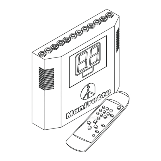
INSTRUCTIONS
851 - 852 - 850 - 854-4 - 854-6 - 854-10
M
OTORISED EXPAN BACKGROUND SUPPORT SYSTEM
Table of
Contents
Previous
Page
Next
Page
1
2
3
4
5
Advertisement
Table of Contents
Need help?
Do you have a question about the 851 and is the answer not in the manual?
Ask a question
Questions and answers
Related Manuals for Manfrotto 851
Control Unit Manfrotto 852 Instructions Manual
Motorised expan background support system (17 pages)
Control Unit Manfrotto 850 Instructions Manual
Motorised expan background support system (17 pages)
This manual is also suitable for:
852
850
854-4
854-6
854-10
Table of Contents
Print
Rename the bookmark
Delete bookmark?
Delete from my manuals?
Login
Sign In
OR
Sign in with Facebook
Sign in with Google
Upload manual
Upload from disk
Upload from URL


Need help?
Do you have a question about the 851 and is the answer not in the manual?
Questions and answers