Table of Contents
Advertisement
Quick Links
SOMMAIRE
1
2
3
4
4.1
Public-Address Matrix.............................................................................................................................. 4
4.2
Audio signal transportation application .................................................................................................... 5
4.3
Use of « Matrix Control » ......................................................................................................................... 7
5
5.1
DN 3816 matrix package contents........................................................................................................... 7
5.2
Front panel .............................................................................................................................................. 7
5.2.1
5.2.2
5.2.3
5.2.4
5.2.5
5.2.6
5.2.7
5.2.8
5.2.9
5.3
Rear panel .............................................................................................................................................. 8
5.3.1
5.3.2
5.3.3
5.3.4
5.3.5
5.3.6
5.3.7
5.3.8
5.3.9
5.3.10
5.3.11
5.3.12
6
6.1
Block diagram of the DN 3816 audio channels........................................................................................ 9
6.1.1
6.1.2
6.1.3
7
CABLING, CONNECTIONS AND STARTING UP THE DN 3816 .................................................................... 9
7.1
Mains power connection .......................................................................................................................... 9
7.2
+24 V power supply ................................................................................................................................. 9
7.3
Audio input and output connections....................................................................................................... 10
7.4
Connecting to EtherSound Network....................................................................................................... 10
7.5
Connecting GX 3016 consoles and an RS232 serial control device...................................................... 10
7.6
Connecting an RS232 serial control device to the Data Link ................................................................. 11
7.7
RS232 socket on the front panel............................................................................................................ 11
7.8
Logic GPI (General Purpose Input) wiring ............................................................................................. 11
7.8.1
7.9
Logic GPO (General Purpose Output) wiring......................................................................................... 12
7.9.1
7.10
Starting up the DN 3816 ........................................................................................................................ 12
8
CONFIGURING THE DN 3816 ...................................................................................................................... 13
8.1
Hardware configuration: setting the physical parameters of the audio inputs ........................................ 13
8.2
Software configuration ........................................................................................................................... 14
8.2.1
................................................................................................................................................... 3
.................................................................................................................. 3
....................................................................................................................................... 3
................................................................................................................................................... 4
................................................................................................................................................... 7
Ventilation grill ................................................................................................................................. 7
Green power ON indicator ............................................................................................................... 7
Green STATUS indicator ................................................................................................................. 7
Green input SIGNAL indicators........................................................................................................ 7
Red input CLIP indicators ................................................................................................................ 7
Green output SIGNAL indicators ..................................................................................................... 7
Red output CLIP indicators .............................................................................................................. 7
RS232 socket .................................................................................................................................. 7
Network activity leds ........................................................................................................................ 7
NETWORK connector...................................................................................................................... 8
CONSOLE connector ...................................................................................................................... 8
GP Inputs connector block............................................................................................................... 8
GP Outputs connector block ............................................................................................................ 8
Serial Number label ......................................................................................................................... 8
Analog Inputs 1 to 8......................................................................................................................... 8
Analog Outputs 1 to 16 .................................................................................................................... 8
24 V socket...................................................................................................................................... 8
MAC address ................................................................................................................................... 8
Ground point.................................................................................................................................... 8
Mains block...................................................................................................................................... 8
ON / OFF switch .............................................................................................................................. 8
.................................................................................................................................................... 9
Mic/Line audio inputs (1 to 4)........................................................................................................... 9
Line audio inputs (5 to 8) ................................................................................................................. 9
Audio outputs (1 to 16) .................................................................................................................... 9
Using GPIs..................................................................................................................................... 12
Using GPOs................................................................................................................................... 12
Functional definition....................................................................................................................... 14
480 avenue de Paris -82000 MONTAUBAN France
Tél. 33 (0)5 63 21 30 00 - Fax : 33 (0) 5 63 03 08 26
FR 12352375877 - 352 375 877 RCS MONTAUBAN
D
N
3
8
1
D
N
3
8
1
Digital audio 8x16
EtherSound Matrix
-http://www.bouyer.com
6
6
Advertisement
Table of Contents

Summary of Contents for Bouyer DN 3816
-
Page 1: Table Of Contents
Line audio inputs (5 to 8) ......................... 9 6.1.3 Audio outputs (1 to 16) ........................9 CABLING, CONNECTIONS AND STARTING UP THE DN 3816 ..............9 Mains power connection .......................... 9 +24 V power supply ..........................9 Audio input and output connections....................... 10 Connecting to EtherSound Network....................... - Page 2 Adjusting Delay on the audio outputs ................18 8.2.2.2.4 Adjusting Volume on the audio outputs ................18 MONITORING THE DN 3816 SWITCH MATRIX STATUS ................18 Monitoring audio levels .......................... 18 Verifying the DN 3816’s switch matrix routing ..................18 Monitoring GPI status ..........................
-
Page 3: Introduction
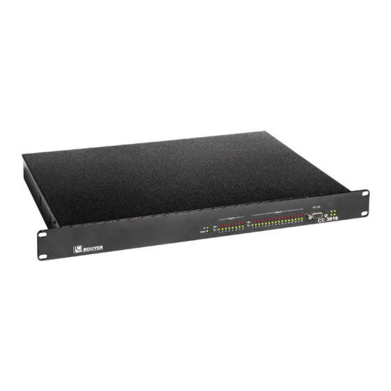
The DN 3816 is a programmable digital audio routing matrix with a wide range of features and applications. Basically, the DN 3816 can be used to switch 8 audio input channels to 16 audio output channels. Switching may be triggered in a number of ways including according to audio input priority levels. The DN 3816 also offers audio signal processing such as sound detection, noise gate, tone adjustment and a 5 band parametric equaliser. -
Page 4: Applications
DN 3816 (by preliminary settings) without intervention of the server application ; in this case, the server application is notified by the DN 3816 when actions are achieved ; this is possible, for example, when a source switching is always operated on one or several zones of the same matrix and when the triggering of this action is managed by the matrix (local console, local remote, …). -
Page 5: Audio Signal Transportation Application
Audio signal transportation application The DN3816 matrix can be used to achieve audio signal transportation between 2 or several distant places through an Ethernet link. This functionality doesn’t require any application server. In all cases, transported signals benefit from all audio processing : volume, bass/treble, noise gate (settings to do on inputs side) volume, 5 band equalization, delay (settings to do on outputs side) Example n°... - Page 6 Exemple n° 2 : transportation of 8 audio signals from 1 place to 4 distant places through optic fiber link Fibre Optique/Ethernet Network 8 signaux audios 1 à 8 Optic fiber to Ethernet 8 audio signals 1 to 8 DN3816 Ethernet/Fibre Optique Network Ethernet to optic fiber...
-
Page 7: Use Of « Matrix Control
RS232 socket This 9-pin SUB-D female connector is used to connect a PC to the DN 3816 so the unit can be configured using the « Matrix Control » configuration software supplied. This connection is also used to update the DN 3816 firmware as necessary. -
Page 8: Rear Panel
This information is the MAC address of the DN3816 (used for software settings on application server. 5.3.10 Ground point Use this connector to ground the DN 3816 matrix to earth when fitting the unit inside a rack cabinet. In certain circumstances, earthing the unit will considerably reduce hum, noise and interference. 5.3.11... -
Page 9: Installation
The unit comes complete with everything needed to mount it into a 19” rack. Just four M6 screws are used to rack the unit. The DN 3816 must not be exposed to water (through splashing, from condensation, etc.). Ensure the front and rear ventilation grills are kept clear at all times and that air flow around the unit is not restricted. -
Page 10: Audio Input And Output Connections
Up to two GX 3016 console buses can be connected to the DN 3816. All the consoles on the same RS485 bus occupy just one audio channel. The consoles determine automatically which gets to use (occupy) the single audio channel. -
Page 11: Connecting An Rs232 Serial Control Device To The Data Link
RS232 socket on the front panel The DN 3816 matrix is fitted with an RS232 port so it can be connected up to a PC. Use the 9-pin SUB-D male- female connector supplied to connect the PC to the DN 3816 matrix... -
Page 12: Using Gpis
Logic GPO (General Purpose Output) wiring The DN 3816 matrix has 16 logic open-collector transistor general purpose outputs (logic GPOs). The logic GPOs may be connected directly to the relay contacts of external equipment to provide them with information on the state of the matrix. -
Page 13: Configuring The Dn 3816
The DN 3816 matrix input type on audio inputs IN 1 to IN 4 can be changed. This can be done using the configuration jumpers located on the interface board situated inside the matrix along the back plane. -
Page 14: Software Configuration
LINE pins as required. To enable a phantom supply (SUPPLY 1 and SUPPLY 2) on the corresponding inputs IN 1 or IN 2, fit the corresponding SUPPLY jumper: First ensure that the DN 3816 is switched off and that the power cable is unplugged before opening up the unit. -
Page 15: Modulation Detection
GX 3016 This source type is reserved exclusively for the DN 3816 matrix’s audio inputs 5 and 6. Input channel 5 must be set to type GX 3016 if a set of GX 3016 consoles is to be connected to bus 1 of the switch matrix. -
Page 16: Setting The Group Parameters
These parameters can be set under the « Groups » tab. The DN 3816 includes the option of programming groups of outputs so that, for example, an audio input can be directed to a group of audio outputs. In applications involving sound and PA systems in public places, different groups of outputs may correspond to different geographical zones, where each zone has its own particular set of loudspeakers. -
Page 17: Broadcast In Progress
8.2.2.1.1 Using Noise Gate on audio inputs Each of the DN 3816’s inputs incorporates a digital noise gate which may be very useful for eliminating earth hum, interference and other system background noises which may randomly occur. The noise gate feature uses a powerful dynamic processor that works like an automatic gate that lets through only the useful part of the signal. -
Page 18: N.b.: The Effect Of Equalisation On Voice Sounds
MONITORING THE DN 3816 SWITCH MATRIX STATUS The various states of the matrix can be checked in real time either by directly observing the indicators on the DN 3816’s front panel, or by using the « Matrix Control » software. The following paragraphs describe the various options available when using the software application. - Page 19 DN3816...
-
Page 20: Detailed Technical Specifications
Once your product has come to the end of its useful life, and if it is located within France or any French Overseas Territory, please contact BOUYER to arrange for it to be displosed of in compliance with DEEE directives. -
Page 21: Appendices
APPENDICES 12.1 Factory Settings The factory settings are the settings the DN 3816 switch matrix is configured with immediately before it leaves the factory. 12.1.1 Hardware Configuration Audio input Type IN 1 Line IN 2 Line IN 3 Line IN 4 12.1.2... -
Page 22: Default Configuration Of Groups
12.1.4 Default configuration of groups Only group 1 is created: it is made up of all audio outputs. Audio outputs Group 12.1.5 Default configuration of the GX 3016 keys Valid for two GX 3016 consoles (audio inputs 5 and 6) Function Output or Group number... -
Page 23: Default Configuration Of Logic Gpos
12.1.7 Default configuration of logic GPOs Audio inputs Output n ° Function 3 4 5 6 7 GPO 1 Broadcast in progress X X X X X Out 1 GPO 2 GPO 3 GPO 4 GPOs GPO 5 GPO 6 GPO 7 GPO 8 This configuration is used to generate a “Broadcast in Progress”...
Need help?
Do you have a question about the DN 3816 and is the answer not in the manual?
Questions and answers