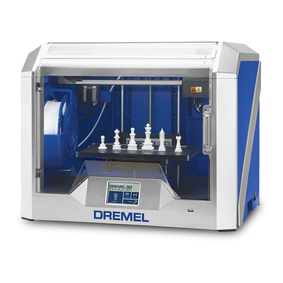
Dremel 3D40 Instructions
Replacing the leveling servo motor assembly
Hide thumbs
Also See for 3D40:
- Original instructions manual (416 pages) ,
- Operating and safety instructions manual (108 pages) ,
- Manual (4 pages)
Table of Contents
Advertisement
Quick Links
WARNING
Read the Dremel 3D40 manual and these
instructions before replacing the level-
ing servo motor in your Dremel 3D40. Failure to comply
with the warnings and instructions may result in fire,
equipment damage, property damage, or personal injury.
Always unplug Dremel 3D40 from its power before per-
forming any service procedures. Failure to do so may re-
sult in personal injury and equipment damage.
Use only Dremel approved materials and components.
Use of object materials, or 3D objects other than Dremel ap-
proved object materials and genuine Dremel components
may void warranty.
Repairs on the Dremel 3D40 may require the use of special
tools (pulling devices and bearing press). Authorized repair
centers have trained repair technicians and equipment nec-
essary to perform these repairs.
CAUTION
Use proper anti-static precautions when
performing this replacement. Discharge
static electricity before beginning. Work on a static-free sur-
face.
This document will outline the steps necessary to replace a
defective or damaged leveling assembly. This includes the
leveling switch, servo motor, and mounting bracket.
Figure 1: Replacement levelling servo motor assembly
Dremel 3D40 – Replacing the
leveling servo motor assembly
For the location of the repair center near you, please call 1-
844-4DRML3D (1-844-437-6533) Monday thru Friday, 8AM
to 6PM CST. Or, look on our web site at www.Dremel3D.com
and follow the link for 'Support'.
CONTINENTAL UNITED STATES
Dremel Service Center
4915 21st Street
Racine, WI 53406
Phone: 1-844-4DRML3D
SERVICE
Tools Required:
• 2mm Hex wrench (Allen key)
• T10 Torx (star) screwdriver bit
• Scissors
Step 1: Bring Printer to Safe State for Service
1. Turn on the printer, and verify that the temperature icon
reads cool (blue). If it is not blue, allow adequate time for
the nozzle to cool until the icon reads blue.
Figure 2: Home Screen (see encircled nozzle temperature)
2. Turn off the printer.
3. Unplug the printer.
CANADA
Giles Tool Agency
47 Granger Ave,
Scarborough, ON
M1K 3K9, Canada
Phone:1-416-287-3000
West Coast Tool
4008 Myrtle Street
Burnaby, B.C. V5C 4G2
Phone: 1-604-873-5394
Advertisement
Table of Contents

Related Manuals for Dremel 3D40


Summary of Contents for Dremel 3D40
- Page 1 West Coast Tool may void warranty. 4008 Myrtle Street Burnaby, B.C. V5C 4G2 Repairs on the Dremel 3D40 may require the use of special Phone: 1-604-873-5394 tools (pulling devices and bearing press). Authorized repair centers have trained repair technicians and equipment nec- essary to perform these repairs.
- Page 2 Step 2: Remove Top Cover of Extruder Step 3: Removing the Shielded Circuit Cable 1. Cut the filament just before the intake on the top of the 1. Using the 2 black push pins (top encircled yellow, bottom extruder. hidden) of the shielded circuit ribbon cable, push down to release it from the circuit board.
- Page 3 1. With the printer turned off, insert the supplied USB stick into the USB port on the front of your 3D40. 2. Turn on the printer and wait for the calibration screen to Figure 9: Take note of how levelling switch is located appear.
- Page 4 b. Visually judge if the leveling arm is vertical. If not, press + to increase angle or – to decrease angle in front of “down” as shown in Figure 12 below. Figure 15 h. Once the angles are adjusted for both vertical and stowing positions, press “next”.
- Page 5 3. Build the “Test Print” file on the machine to ensure the decrements) and test by repeating Step 8 above, before 3D40 printer is working correctly. making any further z axis offset adjustments. 4. If prints are not adhering to the build plate, the z-axis offset may need to be adjusted.
Need help?
Do you have a question about the 3D40 and is the answer not in the manual?
Questions and answers