Table of Contents
Advertisement
Advertisement
Table of Contents

Subscribe to Our Youtube Channel
Summary of Contents for Bofa AD 350
- Page 1 AD 350 FUME EXTRACTION UNIT Version 10.08.2011...
-
Page 2: Table Of Contents
Replacing Filters ......................13 Filter replacement indication ..................14 Pre filter replacement ..................14 Combined filter replacement ................. 15 Fuses ........................... 15 Maintenance Protocol ....................16 Filter Disposal ......................16 Trouble Shooting ....................17 Unit: AD 350 ....................18 Version 10.08.2011... -
Page 3: Safety Instructions
SAFETY INSTRUCTIONS Symbols used Danger Refers to an immediately impending danger. If the danger is not avoided, it could result in death or severe (crippling) injury. Risk of electric shock. Consult manual where this symbol is displayed. Warning Refers to a possibly dangerous situation. If it is not avoided, it could result in death or severe injury. -
Page 4: Warning And Information Labels
Warning and Information Labels Label/Symbol Position Side of the unit, next to the Protex clip Rear of Base of unit above inlet port Pump/motor access panel / exhaust box Next to power inlet connection Version 10.08.2011... -
Page 5: Installation
INSTALLATION Introduction When a component is laser marked an amount of the surface of the substance is thermally decomposed, “burnt off”. This thermal decomposition comprises a mixture of particulate and gaseous compounds. The heat energy causes the gases and surrounding air to quickly expand moving away from the surface at high velocity entraining any particulate with the gases. -
Page 6: Enclosures
Purge air should be kept to a minimum, where possible, to prevent the fume being blown away from the nozzle High speed bottling lines may need bigger scoops or nozzles both sides of the bottles because of the turbulence caused by the speed of the bottles Fig. -
Page 7: Extractor Overview
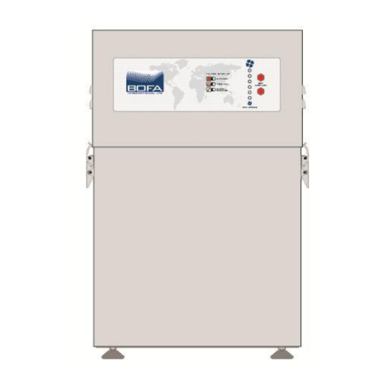
The AD range provides extraction and filtration of the fume generated by laser marking, cutting, etching or engraving. These units are of robust design and feature ease of use with minimal maintenance. The main components of the AD 350 are shown in fig.5 below. Items may vary slightly. Fig 5. -
Page 8: Extractor Installation Procedure
Extractor Installation Procedure Caution If this equipment is used in a manner not specified by the manufacturer, the protection provided by the equipment may be impaired. Read all instructions in this manual before using this extractor. 1. Move the unit to the location where it is going to be installed and remove the unit from its packaging. -
Page 9: Optional Extra Feature Considerations
Optional Extra Feature Considerations The below features are optional extras that will only be fitted if requested at the time of ordering the unit. 5. If fitted, the following features need to be considered when installing the unit: Important If the AD unit has an exhaust air outlet spigot fitted, the exhausted air can be routed outside of the building if required. -
Page 10: Electrical Supply Connection
Electrical supply connection 6. Check the integrity of the electrical power cable. Connect the power cable to an isolated electrical supply. The mains socket outlet should be installed near the equipment and be easily accessible. The cable run to the machine should be arranged so as not to create a trip hazard. -
Page 11: Operation
OPERATION Manual operation Stainless steel AD units are turned on by depressing the green button on the front of the extractor and turned off by depressing the red button. (See fig 9). Powder coated AD units are turned on and off by means of a green, illuminated rocker switch on the rear of the unit, (See Fig 9). -
Page 12: Gas Filter Change Led (Voc Monitoring)
Front Panel – No VOC monitor fitted Fig 10 Gas Filter Change LED (VOC monitoring) Units equipped with a VOC sensor detect the level of Volatile Organic Compounds in the exhausted air. If their presence exceeds a preset level the Alarm LED on the front panel will illuminate. -
Page 13: Maintenance
Bofa can provide this service, our inspectors are BOHS P601 qualified, and copies of the required initial information and forms are included in the Log book supplied with the extractor. -
Page 14: Filter Replacement Indication
Filter replacement indication The first few filter changes should only apply to the pre-filter. The indication that the HEPA portion of the combined filter is blocked and that the filter needs replacing is when the green amber and red LED’s do not go off after the pre filter has been changed. -
Page 15: Combined Filter Replacement
Combined filter replacement If the Filter monitoring option is fitted the requirement for combined filter change is indicated by the filter alarm signal and LEDs not going off after the pre filter has been changed. For units fitted with the VOC monitor option, the requirement for a combined filter change (gas portion saturated) is indicated by illumination of the Gas filter alarm light on the front panel. -
Page 16: Maintenance Protocol
Maintenance Protocol Filters to be changed in accordance with instructions. Log the date of filters changed in the table below: Unit Serial Number Pre Filter Combined Filter Date Name Date Name Filter Disposal Pre and combined filters are manufactured from non-toxic materials. Filters are not re-usable, cleaning used filters is not recommended. -
Page 17: Trouble Shooting
Trouble Shooting In the unlikely event of a problem with your AD extractor please contact your local representative. BOFA International LTD 21-22 Balena Close Creekmoor Industrial Estate Poole, Dorset BH17 7DX, UK Tel: +44 (0)1202 699444 Fax: +44 (0)1202 699446 Email: technical@bofa.co.uk... -
Page 18: Unit: Ad 350
Appendix System Specifications Unit: AD 350 Capacity: 400 m³/hr (236cfm) Size: Height 600mm x Depth 380mm x Width 380mm Height 23.62” x Depth 14.96” x Width 14.96” Weight: 40Kg (88.2lb) Exhauster: Centrifugal Fan Output: 1.1kw Electrical supply: 115-230v 1ph 50Hz FLC: 12.5A...
Need help?
Do you have a question about the AD 350 and is the answer not in the manual?
Questions and answers