Table of Contents
Advertisement
Advertisement
Table of Contents

Related Manuals for Newall NMS 300

Summary of Contents for Newall NMS 300
- Page 1 NMS 300 Digital Readout User Manual...
-
Page 2: Table Of Contents
Contents Specification Page 3 Electrical Page 3 Physical Page 3 Environment Page 3 Accreditation Page 3 Disposal Page 3 Input and Resolution Page 3 Mounting Options Page 4 Mill Mount Page 4 Lathe Mount Page 4 Connection Details Page 5 Important Information Page 5 Connections... -
Page 3: Specification
Only Spherosyn 300 or Microsyn 300 encoders can be used with the NMS300 DRO Resolutions Spherosyn 300 Microsyn 300 5μm (0.0002”) 2µm (0.0001”) 10μm (0.0005”) 5μm (0.0002”) 20μm (0.001”) 10μm (0.0005”) 50μm (0.002”) 20μm (0.001”) 50μm (0.002”) Newall Measurement Systems Limited reserves the right to make changes to this specification without notice... -
Page 4: Mounting Options
Mounting options Standalone Mount Options Swivel Mount Option Panel Mount Option 210.00 2.50... -
Page 5: Connection Details
Connection details Important Details The NMS300 is only compatible with Newall Spherosyn 300 and Microsyn 300 encoders. It is important to ensure that: Secure all the cables to prevent the connectors from dropping into hazardous positions (for example the floor or coolant tray) when they are unplugged. -
Page 6: Display And Keypad
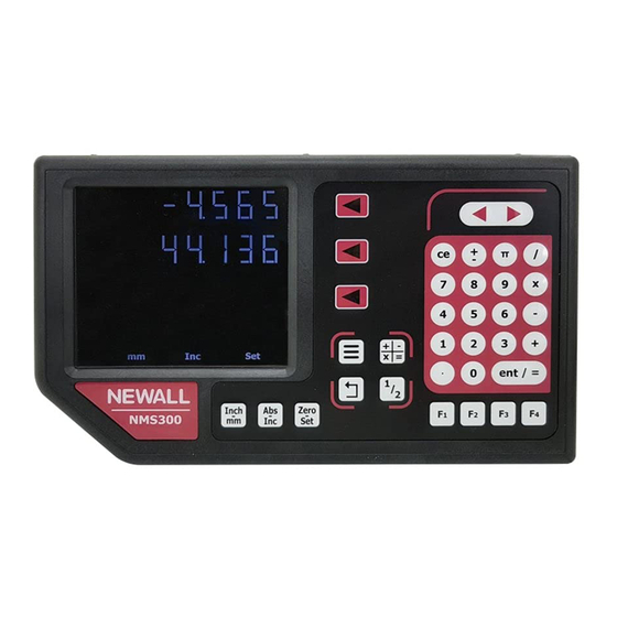
Display and keypad Understanding The Display 950. 3 55 Axis 1 100. 2 50 Axis 2 -156. 7 55 Axis 3 Message display Zero Understanding The Keypad Switches between zero Axis selection key and axis pre-set modes Switches between absolute and incremental modes Switches between inch and mm display... -
Page 7: Setting Up The Unit
Setting up the unit How to enter setup DRO setup code setup- Language EnG Gb Deutsch Francais Italiano Espanol setup- DRO TYPE Generic mmill lathe setup- 0. 0 05 00. 0 2 0. 0 1 Dependant on encoder (see page 9) 0. -
Page 8: Navigating Complete Setup (Continued)
Setting up the unit setup- func func - func - digifind func - feed func - line func - func - Pocket func - func - taper DO NOT SCALE THIRD ANGLE PROJECTION IF IN DOUBT ASK func - tool DO NOT SCALE THIRD ANGLE PROJECTION IF IN DOUBT ASK... -
Page 9: Language Setup
Setting up the unit Language Setup This setting enables the user to choose the language that is required to be displayed in the NMS300 display. There are language settings: English UK (Default) EnG Gb English US Spanish French Espanol Francais German Italian Deutsch... -
Page 10: Direction Of Travel Setup
The first step in determining the source of error is to check the DRO system. To do this compare the movement of the Newall reader head to the position reading shown on the display. A high accuracy standard, such as a laser interferometer is required. A dial indicator can be used to check short distances, but a laser provides the best results. - Page 11 To check the accuracy of the DRO system: 1. Place the target of the laser or the needle of the dial indicator directly on the Newall reader head. It is absolutely critical that the readings are taken directly from the Newall reader head. If a dial indicator must be used, be sure that the needle of the indicator is perpendicular to the reader head and not angled.
-
Page 12: Linear Error Compensation
Setting up the unit Linear Error Compensation In this mode, a single constant correction factor is applied for each axis for all displayed measurements. Calculate the correction factor, and specify it in parts per million (ppm). When following the procedure ensure that a stepped standard is used, and approach each edge from the same direction;... - Page 13 Setting up the unit Teach Mode Continued last compensation value calculated / used to choose teach rather than program lin1- teach encoder position (start point) 0. 0 00 tch1- start encoder position (end point) 1000. 0 00 tch1- enter the actual measurement using the numeric keypad tch1- movement value entered in previous step...
- Page 14 Setting up the unit Program Mode Program mode allows the linear compensation to be calculated manually and then entered as a PPM val- ue into the NMS300 display. The procedure to do this is shown below: To illustrate the calculation an example is being used where the standard distance is 500.000mm and the measured distance is 500.200mm.
-
Page 15: Segmented Error Compensation Setup
Setting up the unit Segmented Error Compensation The scale travel is broken down into as many as 200 user-defined segments, each with their own correc- tion factor, measured against a high-accuracy standard. The following parameters need to be identified: Each Correction Point is measured with respect to the Starting Point - zero - which is usually set close to one end of the scale. - Page 16 Setting up the unit Teach Mode Continued encoder position (position 1) 2. 0 00 tch1- go to 001 enter the actual measurement using the numeric keypad tch1- movement value entered in previous step 2. 1 50 tch1- movement compensation value 0.
-
Page 17: Using Segmented Error Compensation
Setting up the unit Program Mode Navigate to the Error compensation selection screen setup- err comp The default value for each of the axis is nonE Press the axis select key next to the ‘X’, ‘Y’ or ‘Z’ axis that requires segmented compensation the message display will show (CMP 1 = X axis, CMP 2 = Y axis &... -
Page 18: Plane Setup
Setting up the unit Plane Setup This setting defines the machining face of the work piece, for example; on a turret mill it would typically be the X Axis and the Y Axis. This setting is used by the mill functions. e-------3 e-------3 e-------3... -
Page 19: Feed Setup
Setting up the unit Feed Setup mminutes to change between minutes and seconds setup- feed Settings available are: in/minutes, in/second, mm/minutes & mm/second seconds to change from inches to millimetres in conjunction with this function setup- feed Brightness Setup The default brightness is medium mmid setup- bright... -
Page 20: Sleep Setup
Setting up the unit Sleep Setup This setting enables the user to define an automatic sleep mode after a period of time. The user either leaves the default setting at 0 which deactivates the sleep mode, or inputs a value (in whole minutes) for when the sleep mode is initiated after no operation of the NMS300. -
Page 21: Standard Functions
Standard functions Absolute / Incremental Press the key to toggle between absolute and incremental Absolute (abs) mode has modes. been selected The NMS300 has a dedicated key to switch the positional displays between absolute (abs) and incremental (inc) measurements. The current display mode is indicated at the bottom of the screen as shown on the right. -
Page 22: Inch / Mm
Standard functions Inch and mm modes Press to toggle between Inch and mm measurement modes. Metric (mm) mode has been selected The NMS300 has a dedicated key to switch the positional displays between imperial (inch) and metric (mm) measurements. The current display mode is indicated at the bottom left of the screen as shown right. -
Page 23: Undo Function
Standard functions Undo function The NMS300 stores the last 10 positions / numeric inputs, which can be accessed using the undo feature. Example 1 - non movement display shows input a value -145. 2 30 95. 5 20 an incorrect figure has been accepted but the dimension shown previously is required. press display now shows -145. -
Page 24: Function Menu / Function Keys
Standard functions The NMS300 has multiple ways of accessing functions, via the main menu & the function keys. Functions Menu Function menu Generic & Lathe menu - tool menu - Generic & Mill menu - line Generic & Mill menu - Generic &... - Page 25 Digifind / reference function The NMS300 comes equipped with Digifind, a feature unique to Newall digital readout products. Digifind eliminates the risk of losing position and datum Set-Up. With Digifind, precise Set-Up of a work-piece is carried out only one time.
-
Page 26: Reference
Standard functions Digifind / reference function continued To use digifind one of the function keys must be assigned to the digifind function - see the section function keys Setting the reference Press the function key that has been assigned to digifind, (in this example the digifind has been assigned to the F4 key). ST rf- sel axis digi-... - Page 27 Standard functions Teach Mode To use sub datums one of the function keys must be assigned to the sub datum (SDM) function - see the section function keys Press the function key that has been assigned to sub datums, (in this example the sub datum has been assigned to the F3 key).
-
Page 28: Feed Rate
Standard functions Use Mode Press the function key that has been assigned to sub datums, (in this example the sub datum has been assigned to the F3 key). sdm- sdm- 001 or use the numeric keypad to input sub datum required sdm- 002 to exit SDM use and return to SDM menu, or to exit setup and return to measurement display... -
Page 29: Mill Functions
Mill functions PCD / bolt hole circle To use PCD / bolt hole circle one of the function keys must be assigned to the PCD function - see the section function keys Press the function key that has been assigned to PCD, (in this example the PCD has been assigned to the F2 key). The NMS300 calculates positions for a series of equally spaced holes around the circumference of a circle. -
Page 30: Line Hole
Mill functions Line hole To use line hole one of the function keys must be assigned to the line hole function - see the section function keys Press the function key that has been assigned to line hole, (in this example the line hole has been assigned to the F3 key). The NMS300 calculates positions for a series of equally spaced holes in a line. -
Page 31: Arc Contouring
Mill functions Arc contouring To use arc contouring one of the function keys must be assigned to the arc contouring function - see the section function keys Press the function key that has been assigned to arc contouring, (in this example arc contouring has been assigned to the F4 key). The NMS300 calculates positions for a series of equally spaced holes in an arc. -
Page 32: Pocket / Island
Mill functions Pocket / Island Milling To use pocket milling one of the function keys must be assigned to the pocket milling function - see the section function keys Press the function key that has been assigned to pocket milling, (in this example pocket milling has been assigned to the F1 key). The NMS300 calculates positions for each corner of pocket / island required. -
Page 33: Lathe Functions
Lathe functions Tool Offsets To use tool offsets one of the function keys must be assigned to the tool offset function - see the section function keys Press the function key that has been assigned to tool offsets, (in this example tool offsets has been assigned to the F1 key). The NMS300 can store up to 50 tool offsets, this large number allows tools to be grouped where more than one set is used. - Page 34 Lathe functions Use Mode tool- TL- 01 to select different tool Note: Different tools can be selected by entering the tool number required using the numeric keypad Quick Edit Mode While in the using tool offsets mode tools can be edited / created quickly, without having to go back though the tool program or teach modes.
-
Page 35: Taper Turning
Lathe functions Taper Turning To use taper one of the function keys must be assigned to the taper function - see the section function keys Press the function key that has been assigned to taper, (in this example taper has been assigned to the F2 key). The taper function shows the angular displacement of the displayed (X,Z) position. -
Page 36: Trouble Shooting
2.1 appears in the display This type of error can only be cleared by cycling the power to the NMS300. If the solutions suggested above do not solve the problem, contact Newall for further instruction. To swap encoders to trace a fault: 1. - Page 38 More information at Sales@machine-dro.co.uk www.machine-dro.co.uk Document number: 023-82340-UK/0...
Need help?
Do you have a question about the NMS 300 and is the answer not in the manual?
Questions and answers
Cómo puedo sacar mis coordenadas de 5 barrenos el diámetro de centro de barrenos es de 5"
To obtain the coordinates for 5 holes with a center diameter of 5" using the Newall NMS 300:
1. Enter the center coordinate (refer to using set mode, page 22).
2. Enter the PCD (Pitch Circle Diameter) value, which is 5 inches (convert to millimeters if needed).
3. Enter the number of holes, which is 5.
4. Enter the start angle (refer to using set mode, page 22).
- Important: The PCD is calculated from the 3 o’clock position, moving anti-clockwise.
- If the start angle is given clockwise from 3 o’clock, enter it as a negative value.
5. Navigate through the sequence of holes using the controls or numeric keypad.
The NMS300 will calculate and display the distance to each hole.
This answer is automatically generated