Table of Contents
Advertisement
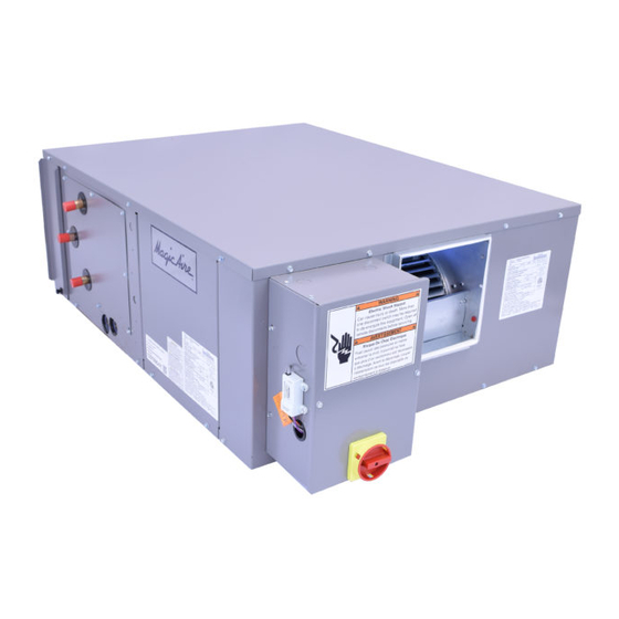
Magic Aire HCA Series units
are direct drive High Efficien-
cy Horizontal Air Handlers
delivering nominal airflows of
400 to 4000cfm and nominal
cooling capacities of 1/2 to 10
tons.
Units may be specified
with chilled water or DX cooling coils and
hot water or steam heating coils to meet
space cooling loads or heating loads or
both.
How to Use this Manual:
This manual gives instructions regarding in-
stallation, operation and maintenance for the
HCA Series air handling units. For more in-
formation refer to:
Catalog brochure for unit dimensions,
options, guide specifications and perfor-
mance information.
New Magic 4 software for faster selection
of new equipment.
Website
www.magicaire.com
placement parts guide, software down-
loads, product data and contact info for
your local Magic Aire representative.
Replacement Parts – Identify parts
needed using the replacement parts
guide available at www.magicaire.com.
Use these instructions in conjunction with
other appropriate instructions, including but
not limited to those instructions supplied with
the outdoor unit (if applicable). Installation
must comply with all applicable local codes.
SAFETY WARNING:
Installer should pay particular attention to the
following words:
NOTE–intended to clarify or make installation
easier.
CAUTION–given to prevent equipment dam-
age.
WARNING–to alert installer that personal inju-
ry and/or equipment damage may result if in-
stallation procedure is not properly followed.
035-000049-001
HCA Series
Installation, Operation and Maintenance
GENERAL
Installation and maintenance are to be per-
formed only by qualified personnel who are fa-
miliar with local codes and regulations and are
experienced with HVAC equipment of this type.
WARNING: Sharp edges, coil surfaces
and rotating fans are a potential injury
for re-
hazard – avoid contact.
WARNING: Hazardous voltage – Discon-
nect and Lock Out all incoming power
sources before servicing or installing unit.
ELECTRIC SHOCK CAN CAUSE DEATH.
WARNING: This equipment may be in-
stalled well above finished floor—Use ex-
treme caution when working at heights.
Immediately inspect each unit for dam-
age upon receipt.
Page 1
Air Handler
Manual
UNPACKING-CHECK FOR DAMAGE!
•
Inspect units for external and concealed
damage immediately.
•
File any damage claims in accordance
with Magic Aire Freight Damage Policy
and Terms and Conditions (available at
www.magicaire.com).
•
Do not repair damaged units without
written authorization.
•
Protect stored units from damage.
HCA IOM 1.1 8-28-2017
Advertisement
Table of Contents

Related Manuals for Magic Aire HCA Series


Summary of Contents for Magic Aire HCA Series
-
Page 1: Safety Considerations
How to Use this Manual: This manual gives instructions regarding in- stallation, operation and maintenance for the HCA Series air handling units. For more in- GENERAL formation refer to: Installation and maintenance are to be per- Catalog brochure for unit dimensions,... - Page 2 THIS PAGE INTENTIONALLY LEFT BLANK 035-000049-001 Page 2 HCA IOM 1.1 8-28-2017...
-
Page 3: Table Of Contents
HCA Series Air Handler Installation, Operation and Maintenance Manual Installa on, Start-Up and Service Instruc ons Topic Page Warranty Registration Form SAFETY CONSIDERATIONS UNPACKING-Remove Shipping Screws PREINSTALLATION Rigging Unit Weight Calculation INSTALLATION 6-18 Unit Suspension External Vibration Isolators Ductwork Electrical... -
Page 4: Unpacking-Remove Shipping Screws
DANGER UNPACKING-CAUTION! NEVER enter an enclosed fan cabinet or reach into After removing the outer packaging, a unit while the fan is running. LOCK OPEN AND TAG the fan motor power dis- REMOVE RED BLOWER SHIPPING connect switch before working on a fan. Take fuses SCREWS with you and note removal on tag. -
Page 5: Preinstallation
Damage to stationary bearings can occur. Set unit off ground if in Magic Aire holds that this practice represents the heavy rain area. standard for professional installation whether or not b. Remove all fasteners and other small parts this code has been adopted in a specific municipal- from jobsite to minimize theft. -
Page 6: Installation
UNIT SUSPENSION port the unit and that the rods extend entirely through their associated fasteners. Ceiling Suspension: Acceptable forms of unit suspension are shown in Fig. 3, 4 and 5. Figure It is recommended that framing be construct- 3 shows suspension rods run through the knock- ed from structural steel or formed-strut mate- outs in top and bottom of the unit. -
Page 7: External Vibration Isolators
UNIT SUSPENSION (CONT’D) Floor mounting: Unit may be mounted on a housekeeping pad, floor or platform. CAUTION! Make sure to allow enough elevation to permit construction of the condensate trap. Vibration Isolators: (field supplied) If required, install isolators in the suspension rod system. Allow clearance as needed between isolators and unit. -
Page 8: Ductwork
INSTALLATION—DUCTWORK DUCTWORK CONNECTIONS Install supply and return ductwork to the unit as required for the application. Note that free discharge or free return is ac- ceptable. Return Ductwork: Install return ductwork by attaching one side of a field-provided flexible duct connector to the duct flange on the return side of the unit (filter side). -
Page 9: Electrical
INSTALLATION-ELECTRICAL DANGER DANGER WARNING: Hazardous voltage. Only qualified NEVER enter an enclosed fan cabinet or reach into personnel must install the electrical service. Dis- a unit while the fan is running. connect and Lock Out all incoming power sources LOCK OPEN AND TAG the fan motor power dis- before connecting to electrical service. - Page 10 INSTALLATION-ELECTRICAL (cont’d) TYPICAL WIRING DIAGRAMS— Control Option “C” Four User-Adjustable Speeds NOTES: 7. The control power (R and C at terminal 1. This diagram represents the factory-installed block TB1) can be used to power a stand- electrical option with 4 user-adjustable speeds. ard 24VAC thermostat , DX relay and up to 2.
- Page 11 INSTALLATION-ELECTRICAL (cont’d) TYPICAL WIRING DIAGRAMS— Control Option “E” Variable Speed 0-10VDC Signal Fan Speed Control NOTES: 7. The control power (R and C at terminal 1. This diagram represents the factory-installed block TB1) can be used to power a stand- electrical option with constant CFM control us- ard 24VAC thermostat , DX relay and up to ing the pressure transducer mounted inside the...
-
Page 12: Service Clearance
SERVICE CLEARANCES CONTROL BOX CONTROL BOX CLEARANCE NOTES: 1. NOT TO SCALE. REFER TO CATALOG DRAWINGS FOR UNIT OUTLINE DIMENSIONS. DIMENSIONS 2. MOTOR IS LOCATED ON THE SAME SIDE AS COOLING COIL UNIT CONNECTION (UNIT WITH 2 COILS) OR 2-PIPE/HEATING COIL CON- NECTION (UNIT WITH SINGLE COIL). -
Page 13: Condensate Drain
Fig. 7 — Condensate Drain INSTALLATION Condensate Drain — Install a trapped condensate drain line at unit drain connection. HCA units have a 3/4 in. FPT condensate drain connection, or alternately a 3/4” male PVC pipe outlet for the condensate drain con- nection. -
Page 14: Steam Coil Piping Recommendations
Steam Coil Piping Recommendations GENERAL — Use straps around the coil casing to lift and place the coil. CAUTION To prevent damage to the coil or coil headers: Do not use the headers to lift the coil. Support the piping and coil connections independently. - Page 15 Steam Coil Piping Recommendations (Cont’d) NOTES (Figure 9): 1. A bypass is necessary around trap and valves when uninterrupted operation is necessary. 2. Bypass to be the same size as trap orifice but nev- er less than 1/2 inch. Fig. 11 — Multiple Coil Low Pressure Piping Gravity Return NOTES: 1.
-
Page 16: Coil Freeze-Up Protection
Steam Coil Piping Recommendations (Cont’d) assembly ensures that condensate will flow toward the drains. This condensate must be Following the piping diagrams in Fig. 8-12, make all removed through the return piping to prevent connections while observing the following precau- premature failure of the coil. -
Page 17: Refrigerant Piping, Direct Expansion (Dx) Coils
SUCTION PIPING — Connect suction piping as shown stalled level to maintain the inherent slope. in Fig. 13 for face split coil. Also ensure the unit is installed high enough to allow the piping to be installed correctly, especially the traps which require long drip legs. - Page 18 There are three different options to control Refrigerant Piping, Direct-Expansion (DX) Coils tons per circuit when using an unloading (Cont’d) compressor. The first is to use drop solenoid valve control as illustrated above and let the EXPANSION VALVE PIPING — Distributor nozzles and suction cutoff unloaders “ride”...
-
Page 19: Start-Up
START-UP Pre-Startup BUILDING ENVELOPE—All building windows and doors should be installed and closed before starting unit. During summer construction, avoid unit sweating by allowing for gradual pull down: use elevated chilled water temperature, reduce chilled water flow rate (gpm), use maximum available airflow. HEATING FLUID TEMPERATURE-Maximum entering water temperature is 180°F, unless nameplate indicates 200°F. -
Page 20: Service
Fan System Periodic Maintenance 9. Leave coil flanges or coupling open and aux- 1. Magic Aire strongly recommends use of a Pre- iliary drain valves open until spring. ventive Maintenance program to insure that the AIR DRYING METHOD OF COIL PROTECTION unit operates safely and efficiently. - Page 21 SERVICE—Fan Motor Replacement (cont’d) temperature drops below 165 F. Note the ther- mal condensate drain is limited to 5 psig pres- 2. Drain coil as described in procedures for Anti- sure. At greater coil pressures they will not freeze Methods of Coil Protection. open.
- Page 22 SERVICE-Coil & Drainpan Removal and Reinstallation Procedure 1. Perform procedure on the ground for safety. If 4. Remove filter door and filter (Figure 17 working at heights USE EXTREME CAUTION and 18). observe all FALL SAFETY considerations. 5. Remove coil retaining screws (4ea sizes Under all conditions, LOCK OUT all power 04-20, up to 6ea sizes 30-40).
- Page 23 SERVICE-Coil & Drainpan Removal and Reinstallation Procedure 6. Remove top panel screws at sides and rear (rear leg and coil panel) to allow top to be lifted up. Front screws can remain. Remove top filter rail. (Figure 21 and 22). WARN- ING! Insure unit is adequately supported...
-
Page 24: Water Quality Guidelines
Poor cooling/heating water quality can cause serious problems. Ground source or open loop water quality varies and therefore should be tested to determine suitability for use with Magic Aire equipment. Test water for hardness, acidity and iron content before the equipment is installed. Poor water quality can cause one or more of the following problems: mineral deposits, sediment deposits or corrosion. -
Page 25: Physical Data
PHYSICAL DATA Unit Size Model HCA Nomi na l Ca pa ci ty (Tons ) Nomi na l Ca pa ci ty (BTU/HR) 12000 18000 24000 36000 48000 60000 Nomi na l Ai rfl ow (CFM) 1200 1600 2000 Fa n Fa n Si ze 97-6T 90-6R... -
Page 26: Dimensional Drawings
035-000049-001 Page 26 HCA IOM 1.1 8-28-2017... -
Page 27: Warranty Registration Form
(10) days of Warranty Department start-up to comply with the terms of the 501 Galveston St. Magic Aire warranty. Form must be com- Wichita Falls, TX, 76301 or pleted to clearly indicate startup for each Email customer.service@MagicAire.com... - Page 28 THIS PAGE INTENTIONALLY LEFT BLANK 035-000049-001 Page 28 HCA IOM 1.1 8-28-2017...
- Page 29 THIS PAGE INTENTIONALLY LEFT BLANK 035-000049-001 Page 29 HCA IOM 1.1 8-28-2017...
- Page 30 HCA Series Air Handler Installation, Operation and Maintenance Manual 035-000049-001 Page 30 HCA IOM 1.1 8-28-2017...
Need help?
Do you have a question about the HCA Series and is the answer not in the manual?
Questions and answers
Hi, Do you have distributor here in Philippines?