Table of Contents
Advertisement
Available languages
Available languages
Betriebsanleitung
Operating Instructions
Notice d'instructions
Prüfstand zur Brems-System-Analyse
Test Bench for Brake System Analysis
Banc d'essai et d'analyse des systemes de freinage
Banco de pruebas para el analisis de los sistemas de frenos
Banco prova per l'analisi del sistema di frenatura
BT 610 / 612 / 640 / 642
und S-Ausführungen / and S versions
Instrucciones de servicio
Istruzioni per l'uso
/ et le modeles S / y versiones S / e versoni S
Abbildungen mit Sonderzubehör
llustrations with optional extras
Advertisement
Table of Contents

Summary of Contents for Nussbaum BT 610
- Page 1 Banco de pruebas para el analisis de los sistemas de frenos Banco prova per l'analisi del sistema di frenatura BT 610 / 612 / 640 / 642 und S-Ausführungen / and S versions / et le modeles S / y versiones S / e versoni S...
-
Page 2: Table Of Contents
Ausgabe der Dokumentation Ersatz- und Verschleißteile 5. 1 Kurzanleitung: Bremsprüfung PKW/LKW mit automati- Technische Daten scher Auswertung und Ausgabe der Dokumentation 13 18. 1 BT 610 Funktionsbeschreibung 18.2 BT 612 Prüfung vorbereiten 18.3 BT 640 / BT 640 MB 7. - Page 3 Spare and wear parts 5. 1 Short instruction: Brake test on passenger car/truck with Specifications automatical evaluation and documentation output 18. 1 BT 610 Functional description 18.2 BT 612 Test preparation 18.3 BT 640 / BT 640 MB 7.
- Page 4 26.11.07 1 689 979 924N...
- Page 5 Deutsch 1 689 979 924N 26.11.07...
-
Page 6: Benutzerhinweise
Schaltschrank wettergeschützt und (Gruppe 1 und Gruppe 2) und den Betreiber der Brems- Schaltschrank-Heizung eingebaut (an Dauerstrom) prüfstände BT 610, 612, 640 und BT 642. – Funktionsbereich Die Bediener der Gruppe 1 sind eingewiesenes Perso- von –20 °C bis +40°C (eingeschränkte Messgenauigkeit) nal der Kfz-Branche. -
Page 7: Sicherheitshinweise
Sicherheitshinweise Beachten Sie die aufgeführten Sicherheitsanweisungen zu Ihrer Es dürfen keine Reparaturen oder sonstige Arbeiten eigenen Sicherheit und der Sicherheit Ihrer Kunden. an einem im Rollensatz des Bremsprüfstandes abge- Die Sicherheitsanweisungen zeigen Ihnen mögliche Gefahren stellten Fahrzeug durchgeführt werden. auf. Gleichzeitig geben sie Ihnen Hinweise, wie Sie sie durch Ihr richtiges Verhalten abwenden können. -
Page 8: Umgang Mit Gefahrstoffen
Der Prüfstand ist spannungsfrei zu machen, bevor Sicherheitshinweise für den Betreiber Wartungsarbeiten durchgeführt werden, z.B. Lampen und Sicherungen auswechseln. Der Bremsprüfstand ist mit Warnleuchte und Arbeiten an der elektrischen Anlage dürfen nur durch Hinweisschild auf Bremsprüfstand oder mit einer Elektrofachkräfte durchgeführt werden. Abschrankung zu kennzeichnen. -
Page 9: Gerätebeschreibung
Gerätebeschreibung In der Übersichtszeichnung (Bild 1) sind die Komponenten des Der Bremsprüfstand BT 610, 612, 640 und 642 besteht aus drei Bremsprüfstandes dargestellt. Alle Bauteile sind mit einer Positi- Hauptgruppen: onsnummer versehen. Diese ist in der Legende erklärt. - Bedien-/Schaltschrank - Anzeigegerät... -
Page 10: Fernbedienung (Sonderzubehör)
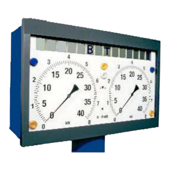
Die Bremsenprüfstände BT 610 und BT 640 verfügen im Gegen- Fernbedienung (Sonderzubehör) satz zu BT 612 und BT 642 über nur eine Prüfgeschwindigkeit. nung ist in Bild 4 zu sehen. Jede Die Tastenbelegung der Fernbedie Bild 3a und 3b zeigen das Anzeigegerät des BT 6xx. Bild 3b in der Taste hat eine Positionsnummer, die in den Bedienschritten in () Ausführung mit 14-stelliger Digitalanzeige (Sonderzubehör) . -
Page 11: Rollensatz
Rollensatz Der Rollensatz des BT 6xx besteht aus einem linken und einem rechten Rollensatz (18), (19), dargestellt in Bild 5b. Bild 5b, Rollensatz: 18. Rollensatz links 19. Rollensatz rechts 29. Tastrolle rechts 30. Tastrolle links 1 689 979 924N 26.11.07... -
Page 12: Kurzanleitung: Prüfung Mit Manueller Auswertung
Kurzanleitung: Prüfung mit manueller Bremskraft langsam steigern. Auswertung Anzeige der Bremskräfte und Bremskraftdifferenz. Automatische Schlupfabschaltung. Kurzanleitung: Bremsprüfung LKW mit manueller Anzeigelampe „Schlupfabschaltung rechts/links" (3) zeigt Auswertung schlupfauslösende Seite. Diese Kurzanleitung richtet sich an Bediener, die mit dem Wird die automatische Schlupfabschaltung nicht erreicht: Umgang mit Bremsprüfständen vertraut sind. -
Page 13: Kurzanleitung: Prüfung Mit Automatischer Auswer
Kurzanleitung: Prüfung mit automatischer Messwerte vor der Bremsprüfung zuweisen. Auswertung und Ausgabe der Dokumenta- z.B.:Prüfung der BBA - Achse 1 tion Taste a (64) oder Kurzanleitung: Bremsprüfung PKW/LKW mit automa- a (64) 1 und E (60) drücken. tischer Auswertung und Ausgabe der Dokumentation Achse 1 der BBA ist eingestellt, die Rollreibung in den Diese Kurzanleitung richtet sich an Bediener, die mit dem Rechner übernommen. -
Page 14: Funktionsbeschreibung
Funktionsbeschreibung Die Bremsprüfstände dienen zur Prüfung der Bremsanlagen an Fahrzeugen. Dazu muss das Fahrzeug mit den Rädern der zu prüfenden Achse (32) in die Rollensätze (18), (19) gefahren werden. Bild 6 zeigt den linken Rollensatz als Schnittdarstellung. (30) 1121 0310 (18) (18) Bild 6:... -
Page 15: Prüfung Vorbereiten
Mit Schalter (11) die Geschwindigkeit wählen zum Messen des Drucks p geeignet, da an dieser Stelle bei (nicht erforderlich bei BT 610 und BT 640). einigen Fahrzeugen, z.B. MB2538L, der Druck voreilt. Dies führt zu Verfälschungen der Prüfprotokolle. In diesen Fällen Taster „Einrichten“... -
Page 16: Fahrzeug Vorbereiten
Fahrzeug vorbereiten Motoren schalten ein Reifendruck am Fahrzeug kontrollieren - wenn nötig korrigieren. Beim Einschalten der Motoren werden die angewählte Achse (1...8) und die angewählte Bremsanlage (BBA, FBA, HBA) ange- ! Sand auf dem Fahrzeugreifen verkürzt die Lebensdauer der zeigt, z.B.: Prüfrollen von Prüfständen erheblich (Schmirgeleffekt). - Page 17 7.3.3 Prüfungsende 7.3.4 Messwerte der Einzelachsen Taste a(64), Nr. der Achse und U (62) drücken. Keine Betriebsart vorgewählt (Automatik/Hand aus) Bei Umschaltung mit Taste U (62) werden folgende Messwerte z.B. Messwerte der Achse 2: Taste a(64), 2 und U (62) drücken. angezeigt : Gesamtauswertung: Achse "X"...
-
Page 18: Radaufhängungstest
Abbremsungsdifferenz [%] Radaufhängungstest Wird der Radaufhängungstester nicht zur Messung Z/Z: 3 von PKWs benutzt, müssen die Abdeckplatten als Rollreibung L/R [kN] Überfahrschutz für schwerere Fahrzeuge auf die Mess- plattformen aufgelegt sein! Zerstörungsgefahr! RR: 1.23 1.78 Vergewissern Sie sich, dass sich keine Personen im Unrundheit L/R [%] Bereich des Prüfstands bzw. - Page 19 Zur Positionierung der Räder stehen folgende Anzeigemöglich- Messwertanzeige keiten zur Verfügung: Das Messergebnis der Bodenhaftung wird direkt nach der Mes- sung auf der 14-Segment-Anzeige (28) als minimale Bodenhaf- - Rad steht vor der Mittenposition (in Fahrtrichtung) tung für das linke/rechte Rad in % (EUSAMA) angezeigt. Linker Zeiger befindet sich unterhalb der 8 Uhr, rechter Zeiger befindet sich unterhalb der 4 Uhr Position.
-
Page 20: Radlauftest
Weitere Erläuterungen zum Radaufhängungstest Radlauftest Bei Hinterrädern von leichten Fahrzeugen mit vorn eingebautem Motor (geringe Achslast hinten, z.B. Panda, Corsa, Twingo, etc.) a) Messung der Vorderachse sind niedrige Bodenhaftungswerte von 20% - 40% normal, ohne dass das Fahrwerk fehlerhaft sein muss. In diesen Fällen ist die Langsam (Schritttempo), gleichmäßig und mittig über den Rad- Differenz als Kriterium ausreichend, wenn die Vorderachse inner- lauftester fahren, dabei nicht lenken. - Page 21 Motorradprüfvorrichtung Um die Messung zur Ermittlung der maximalen Bremskraft zu starten, wird eine Bremskraft > 500 N erwartet. ! Der Hersteller weist ausdrücklich daraufhin, dass eine Ver- wendung der Prüfvorrichtung nur für BT 6xx vorgesehen ist, Hochbremsen der nicht über einer Arbeitsgrube verbaut ist. Bei Erreichen des Bremskraftmaximums (Blockieren des Rades ! Beim Einfahren in den Prüfstand ist besonders auf die auf der Rolle) tritt die Schlupfabschaltung in Kraft und die...
-
Page 22: Messmöglichkeiten
Messmöglichkeiten Orientieren Sie sich an der Leitmarkierung (24). Damit ist sichergestellt, dass Bremsprüfungen können in der Betriebsart „Automatik“ oder - sich die Räder etwa in der Mitte der Prüfrollen befinden, „Hand“ vorgenommen werden. - das Fahrzeug fluchtet, - die Reifenschulter frei steht und nicht die Abdeckplatten streift. Betriebsart „Automatik“... - Page 23 Anzeige an. Wenn die Bremskraftdifferenz 25% überschreitet, leuchtet die Anzeigelampe „Bremskraftdiffe- renz“ (1) auf. Die Bremskraftdifferenz von 25% ist werkseitig eingestellt. Ihr Nussbaum-Kundendienst kann einen anderen Wert einstellen. Wenn die Schlupfgrenze erreicht ist, schalten sich die Antriebs- 1 689 979 924N 26.11.07...
- Page 24 motoren der Rollensätze automatisch ab. Die Anzeigelampe Die Antriebsmotoren schalten sich ab. „Schlupfabschaltung re/li“ (3) zeigt die Seite an, die den Schlupf ausgelöst hat. Mit den Tasten "HBA" (54) 1 oder 2 und E E (60) weisen Sie die Messwerte der FBA von der aktuellen Achse der HBA Wenn bei der Bremsprüfung die Bremskraft so gering ist, dass 1 oder 2 zu.
-
Page 25: Eingabe Für Auswertung Und Dokumentation Durch Den Prüfstand
Eingabe für Auswertung und Dokumentation durch den Prüfstand Die Tabelle „Eingaben für die Protokolle“ zeigt die Werte an, die zur Protokollanforderung eingegeben werden müssen. P r o t o - Eingabe zul. Zug- oder- zul. Hänger- A c h s - Berech- K-Faktor Druck p... -
Page 26: Eingabe Zulässiges Fahrzeuggesamtgewicht
Eingabe zulässiges Fahrzeuggesamtgewicht Beispiel 2: Die FBA der Achse 3 wurde geprüft. Eingabe Zug- oder Gesamtfahrzeug Die Messwerte sollen der HBA 1 zugeordnet werden. Mit den Tasten G (65) 0...9 und E (60) Die Tasten "HBA" (54) 1 (9) "HBA" (54) und "3" (61) das Fahrzeuggewicht in kg eingeben. -
Page 27: Beispiele Für Prüfabläufe
Beispiele für Prüfabläufe 10.1 Prüfablauf PKW Grundsätzlich gilt für alle Prüfabläufe: Vergewissern Sie sich, dass sich keine Personen im - alle Zahleneingaben mit Taste E (60) abschließen Bereich des Prüfstandes aufhalten! - bei Korrekturen von Falscheingaben entweder Eingabe mit E Lebensgefahr für Personen im Bereich der Prüfrollen! (60) beenden oder ca. -
Page 28: Prüfablauf Lkw
Prüfung der FBA z.B. bei Achse 2 10.2 Prüfablauf LKW Hochlaufen der Antriebsmotoren abwarten. Taste h (55) drücken. Bremskraft der FBA langsam steigern, bis die automatische Schlupfabschaltung anspricht. Wenn keine Schlupfabschaltung z2,3 erreicht wird, dann Taste S (58) drücken Vorgaben Fahrzeug aus dem Rollensatz fahren. - Page 29 10.2.1 Prüfablauf Zugfahrzeug Feststellbremsanlage FBA der Achse 2 prüfen. Prüfen von Achse 1 Hochlaufen der Antriebsmotoren abwarten. Achse 1 in den Rollensatz fahren Tasten h (55) drücken. Hochlaufen der Antriebsmotoren abwarten. Bremskraft der FBA langsam steigern, bis die automatische Schlupfabschaltung anspricht. Wenn keine Schlupfabschaltung Taste a (64) und drücken.
- Page 30 Laut Vorgabe gehört die FBA von Achse 3 zur HBA 2 Eingaben von Daten zur Bremskraftauswertung (Daten können auch nach der Prüfung eingegeben werden). Tasten "HBA" (54) 2 (9) "HBA" (54) und "3" (61) "FBA" (55) und "ENTER" (60) drücken. 1.
-
Page 31: Übersichtspläne Der Druckmessstellen
10.3 Übersichtspläne der Druckmessstellen Druckmessstellen im Zugfahrzeug Beispiel: Druckmessstellen (Pfeil) im Zugfahrzeug 1. Druckmessstelle (Kupplungskopf Vorrat) 2. Druckmessstelle (Kupplungskopf Bremse Druck p 3. Druckmessstelle (Druck p 4. Druckmessstelle (Druck p 5. Bremszylinder (Bremskraft F 6. Druckverhältnisventil 7. ALB-Ventil 8. Federspeicherzylinder (Bremskraft F 9. - Page 32 Druckmessstellen im Anhängefahrzeug Beispiel: Druckmessstellen (Pfeil) im Anhängefahrzeug 1. Druckmessstelle (Kupplungskopf Vorrat) 2. Druckmessstelle (Kupplungskopf Bremse Druck p 3. Druckmessstelle (Druck p , Achse 1) 4. Druckmessstelle (Druck p , Achse 2) 5. Druckmessstelle (Druck p , Achse 3) 6. Bremszylinder (Bremskraft F 7.
-
Page 33: Betrieb Mit Wiegeeinrichtung Im Rollensatz (Sonderzubehör)
Betrieb mit Wiegeeinrichtung im Ungeregelter Links-, Rechtslauf Rollensatz (Sonderzubehör) (Sonderzubehör) 11.1 Anwendung 12.1 Anwendung i Das Sonderzubehör Allrad-Prüfung (1 987 009 C1BN für BT Mit der Wiegeeinrichtung wird die auf die Rollen wirkende statische und dynamische Radgewichtskraft erfasst. Mit dieser 610 und BT 640, 1 987 009 C1FN für BT 612 und BT 642) Prüfmethode kann der Bremskraft-Verlauf jeder Einzel-Achse ist als ungeregelter Rechts-/Linkslauf zu verwenden. -
Page 34: Ungeregelter Links-, Rechtslauf
Basis-Kit Funk-Drucksensoren 1 987 009 C1RN 12.2 Ungeregelter Links-, Rechtslauf (Sonderzubehör) Der ungeregelte Links-, Rechtslauf dient der Prüfung von Doppel- achs-LKW, bei denen die Achsen gemeinsam angetrieben wer- Voraussetzungen zur Nutzung des Basis-Kits Funk-Drucksenso- den. Der ungeregelte Links-, Rechtslauf kann auch im PKW- ren am Bremsenprüfstand BT 6xx: Modus betrieben werden. - Page 35 Das Basis-Kit Funk-Drucksensoren eignet sich für die Mehrzahl Basis-Ladestation mit Ladeschalen der Lkws, da diese über ein pneumatisches Bremssystem verfü- gen. Die pneumatischen Drucksensoren arbeiten von 0-20 bar. Die Basis-Ladestation besteht aus einer Wandhalterung, die als Dieser Messbereich ist für alle Funk-Drucksensoren gleich. Die Aufnahme der Funk-Drucksensor-Ladeschalen dient.
- Page 36 LED Signale der Funk-Drucksensoren - Allgemeine Bedeu- Zuordnung von Funk-Drucksensoren auf Fahrzeugachsen tung Nach dem Drücken der CLEAR-Taste <C> (61) auf der IR- Auf jedem Funk-Drucksensor befinden sich drei farbige LEDs in Fernbedienung (Sonderzubehör) gilt folgende Zuordnung: den Farben Rot, Gelb und Grün. Diese zeigen den jeweiligen ·...
- Page 37 BEISPIEL Prüfung eines 3-Achs-Lkw, mit nur einem Prüfanschluss zum Messen von PZ für 2. oder 3.Achse Ablauf der Prüfung: · Funk-Drucksensor PM, PZ1 und PZ2 an den Prüfanschlüssen anbringen · Funk-Drucksensor PZ3 bleibt im Ladegerät · Taste <C> drücken · Zuordnung von Funk-Drucksensor PZ2 zu Achse 3 vornehmen (siehe oben) ·...
-
Page 38: Glossar (Erläuterung Der Fachbegriffe, Abkürzungen Und Formelzeichen)
Abkürzungen: Glossar (Erläuterung der Fachbegriffe, Abkürzungen und Formelzeichen) Betriebsbremsanlage Haftwert Ist das Verhältnis von der Brems- Bremsen-Sonder-Untersuchung kraft des Rades zur Radlast. (ersetzt durch die Sicherheitsprüfung SP, nur BRD) Host-Rechner übergeordneter Rechner ΔZ Differenz der beiden Abbremsungen bei maximaler li/re Bremskraft K-Faktor Faktor, der den Einfluss des Fahr-... -
Page 39: Fehlermeldungen
Fehlermeldungen Fehlercode 00 23 * Fehler beim Auslesen des EPROM. Tritt am Prüfstand ein Fehler auf oder wird eine nicht zulässige Ursache: Betriebsart eingestellt, erscheint auf den Zeigerinstrumenten des - Kein EPPROM vorhanden großen Messbereiches eine Fehlermeldung und die Anzeigelam- - EEPROM defekt. -
Page 40: Fehler Waage
15.2 Fehler Waage Fehlercode 11 05 Kein Signal Tastrollen Endschalter links Fehlercode 10 30 * Ursache: Kein Signal Waagesensor links - Rollensatz ist im Konfigurationsmenü aktiviert, aber physika- Ursache: lisch nicht vorhanden. - Waage ist im Konfigurationsmenü aktiviert, aber physikalisch - Induktivgeber defekt nicht vorhanden. -
Page 41: Fehler Funksensoren
Fehlercode 11 25 * Fehlercode 15 02 * Beim Einschalten vergleich Nullpunkt Pedalkraftmesser (Kabel- Kein Signal Drucksensor Pm (Kabelversion) version) aus EEPROM mit aktueller Pedalkraft. Bei Differenz Ursache: >20N erscheint der Fehler. - Drucksensor Pm (Kabelversion) ist im Konfigurationsmenü Ursache: aktiviert, aber physikalisch nicht vorhanden. -
Page 42: Fehler Radaufhängungstester
15.8 Fehler Radaufhängungstester Fehlercode 18 30 * Ein oder beide zu prüfenden Räder sind während der Messung Fehlercode 18 00 aus der Mitte der Messplatte gerollt. Kein Signal Radaufhängungstester links. Ursache: - Radaufhängungstester ist im Konfigurationsmenü aktiviert, 15.9 Fehler auf der Leiterplatte aber physikalisch nicht vorhanden. -
Page 43: Wartung
Ursache: - Rollensatz ist im Konfigurationsmenü aktiviert, aber physika- lisch nicht vorhanden. Wir empfehlen Ihnen, mit dem Nussbaum-Kundendienst einen - Sensorleitung defekt. Wartungsvertrag abzuschließen. Sie haben damit die Gewähr, - Cal-Check Leitung unterbrochen (Drahtbruch) dass der Bremsprüfstand eine hohe Betriebssicherheit, Zuver- lässigkeit und die vorgeschriebene Messgenauigkeit besitzt. -
Page 44: Ersatz- Und Verschleißteile
Die genauen Bestellnummern für Ihre Prüf- den. Die Stückprüfung ist innerhalb von 4 Wochen erneut durchzuführen. rollen sind vom Nussbaum-Kundendienst zu ermitteln. ! Batterien sind Sonderabfall. Der Termin für die nächste Stückprüfung ist an geeigneter Stelle Sie müssen nach Sonderbestimmungen entsorgt werden! sichtbar am Prüfstand kenntlich zu machen. -
Page 45: Technische Daten
Technische Daten 18.2 BT 612 Zul. Achsgewichtskraft 18.1 BT 610 Zul. Achsgewicht max. Bremskraft je Rad Zul. Achsgewichtskraft Prüfgeschwindigkeit (LKW/PKW) km/h 2,5/5 Zul. Achsgewicht Nennleistung max. Bremskraft je Rad Stern-/Dreieck-Anlaufschaltung (LKW) Prüfgeschwindigkeit km/h Netzanschluss 3 Phasendrehstrom Nennleistung Spannung Volt 400(380) - Page 46 18.3 BT 640 / BT 640 MB 18.4 BT 642 Zul. Achsgewichtskraft Zul. Achsgewichtskraft Zul. Achsgewicht Zul. Achsgewicht max. Bremskraft je Rad max. Bremskraft je Rad Prüfgeschwindigkeit km/h Prüfgeschwindigkeit (LKW/PKW) km/h 2,5/5 Nennleistung Nennleistung Stern-/Dreieck-Anlaufschaltung Stern-/Dreieck-Anlaufschaltung (LKW) Netzanschluss 3 Phasendrehstrom Netzanschluss 3 Phasendrehstrom Spannung...
-
Page 47: Rollensatz Bt 6Xx
18.5 Rollensatz BT 6xx 18.7 Funk-Drucksensor Kleinste nutzbare Achsbreite Basisstation Größte nutzbare Achsbreite 2800 Schnittstelle: RS232 Rollendurchmesser Übertragungsrate: 19,2 kBit/s Rollenlänge 1100 Übertragungsrichtung: bi-direktional vollduplex Mittenabstand Rollen Funk-Drucksensor BT 6xx Gehäuse L x W x H: 135x62x15mm Material: ABS-Kunststoff Antriebsrolle erhöht eingebaut Sensorarten Messbereiche: Rollenbelag Kunststoff + SiC... -
Page 48: Schalleistungspegel Nach Din 45635
Verletzungsgefahr! Die Abdeckung entfällt bei Betrieb über Arbeitsgrube. ungeregelter Links-/Rechtslauf 1 987 009C1BN (für BT 610 und BT 640) ungeregelter Links-/Rechtslauf 1 987 009 C1FN Gewährleistung (für BT 612 und BT 642) Es dürfen keine Veränderungen an unseren Erzeugnissen vorge-... - Page 49 English 1 689 979 924N 26.11.07...
-
Page 50: Considerations For Use
Use in accordance with the regulations Symbol for operating unit and indicator The brake test stands BT 610, 612, 640 and 642 serve for testing the brake systems on vehicles for which general inspec- Information - draws your attention to certain important... -
Page 51: Safety Instructions
Safety instructions Please observe the listed safety instructions for your own safety It is not allowed to perform any repair work or other and for your customer’s safety. work on a vehicle parked in the roller set of the brake The safety instructions point out potential dangers. -
Page 52: Handling Of Dangerous Substances
The electrical system must be protected from moistu- Safety notes for the operator/owner re and wetness. Danger of electric shock! The brake test stand must be marked as brake test stand by means of a warning light and a warning sign Do not perform adjustment work when the test or it must be equipped with a protective barrier. -
Page 53: Description Of Devices
Description of devices The brake test stand components are shown in the general The brake test stand BT 610, 612, 640 or 642 consists of three drawing (Fig. 1). An item number is allocated to each part. All main systems: parts are briefly explained in the legend. -
Page 54: Remote Control (Option)
In contrast to BT 610 and BT 640, only one test speed is available Remote control (option) on the brake test stands BT 612 and BT 642. The key allocation of the remote control is shown in figure 4. Each Figures 3a and 3b show the display unit of the BT 6xx. -
Page 55: Roller Set
Roller set The roller set of the BT 6xx consists of a legt-hand and a right-hand roller set (18), (19), shown in figure 5b. Figure 5b, Roller set: Roller set, left-hand Roller set, right-hand Feeler roller, right-hand Feeler roller, left-hand 1 689 979 924N 26.11.07... -
Page 56: Short Instruction: Test With Manual Evaluation
Short instruction: Test with manual evalua- Slowly increase brake force. tion Indication of brake forces and brake force differential. Automatic slip deactivation. Short instruction: Truck brake test with manual eva- Indicator light „Slip deactivation RH/LH“ (3) shows slip luation cause side. These short instructions are intended for users familiar with If the automatic slip deactivation is not obtained: handling brake test stands. -
Page 57: Short Instruction: Test With Automatical Evaluation
Short instruction: Test with automatical Allocate the measuring values before the brake test. evaluation and documentation output e.g.:Test of SBS - axle 1 Press the key a (64) or Short instruction: Brake test on passenger car/truck press key a (64) 1 and E (60). with automatical evaluation and documentation out- Axle 1 of the SBS is set, the rolling friction is taken over into These short instructions are intended for users familiar with... -
Page 58: Functional Description
Functional description The brake test stands serve for checking brake systems on vehicles. For this test, the vehicle must be driven with the wheels of the axle (32) to be checked into the roller sets (18), (19). Figure 6 shows the left-hand roller set as sectional view. (30) 1121 0310 (18) -
Page 59: Test Preparation
- Pressure sensor (without marking) to the brake cylinder for the Select the speed by means of switch (11) (not required with pressure pz, BT 610 and BT 640). - Pressure sensor (with yellow marking on cable) to the control pressure pm on the coupling head of the brake. -
Page 60: Vehicle Preparation
Vehicle preparation Activation of motors Check the wheel pressure on the vehicle - adjust if necessary. At the time of the activation of the motors, the selected axles (1...8) and the selected braking system (SBS, PBS, AUBS) is ! Sand on the vehicle tire considerably shortens the service life displayed, for instance: of test rollers of test stands (grinding effect). - Page 61 7.3.3 Test end 7.3.4 Measuring values of individual axles Press key a (64), no. of the axle and U (62). No mode of operation pre-selected (automatic/manual operation off). The following measuring values are displayed if change-over e.g. measuring values of axle 2: is performed by key U (62): Press key a (64), 2 and U (62).
-
Page 62: Wheel Suspension Test
Braking difference [%] Wheel suspension test If the wheel suspension tester is not used for measuring Z/Z: 3 passenger cars, the cover plates must be put on as a Rolling friction LH/RH [kN] crossing protection for heavier vehicles to the measu- ring platforms! Danger of destruction! RR: 1.23 1.78... - Page 63 For positioning the wheels, the following display possibilities are Measuring value display available: The measuring result of the wheel grip is displayed on the 14- segment-display (28) directly after the measurement as minimum - Wheel is in front of the center position (in direction of travel) wheel grip for the left-hand/right-hand wheel in % (EUSAMA).
-
Page 64: Wheel Running Test
Further explanations for the wheel suspension test Wheel running test For rear wheels with light-weight vehicles with an engine installed at the front (low axle load at the rear, e.g. Panda, Corsa, Twingo a) Front axle measurement etc.) low wheel grip values of 20% - 40% are normal, whithout that the travelling gear needs to be faulty. - Page 65 Motorcycle test device Braking up ! The manufacturer expressly draws your attention to the fact The slip deactivation comes into operation when the braking force that the use of the test device is only intended for BT 6xx maximum value (wheel blocking on the roller) is reached. The which is not installed above a working pit.
-
Page 66: Measuring Options
Measuring options Orient yourself by the guiding mark (24). In doing so, it is guaranteed that Brake tests can be performed in the automatic mode of operation - the wheels are approximately in the middle of the test rollers, („Automatik“) or in the manual mode („Hand“). - that the vehicle is in alignment, - that the tire shoulder is free and does not touch the cover sheets. - Page 67 8.3.2 Brake test with evaluation by the test stand and Secure the wheels outside the test stand by wheel chocks documentation output if you test the parking brake. Wet brakes falsify the measuring values. Make sure that there are no persons in the test stand Brake the brakes dry with medium braking force! area! Danger to life for any persons in the test roller area!
- Page 68 Slowly increase the braking force. The driving motors are activated again automatically. The display unit shows the braking forces of the left-hand and Slowly increase the parking brake braking force. right-hand wheel brakes. If the braking force difference exceeds If the slip limit is reached, the drive motors of the two roller sets 25 %, the indicator light „Braking force difference! (1) lights up.
-
Page 69: Inputs Necessary For Evaluation And Documentation By The Test Stand
Inputs necessary for evaluation and documentation by the test stand The values which must be entered for log request are listed in the table „Inputs for logs“. Log No. Input Possibilities p e r m i s s i b l e permissible A x l e Calcula-... -
Page 70: Entry Of Permissible Total Vehicle Weight
Entry of permissible total vehicle weight Example 2: The PBS of the axle 3 was tested. Entry of towing vehicle or entire vehicle The measuring values shall be allocated to the AUBS 1. Using the keys G (65) 0...9 and E (60), Press the keys „HBA“... -
Page 71: Test Sequence Examples
Test sequence examples 10.1 Test sequence for passenger car Basically, the following instructions apply to all test se- Make sure that there are no persons in the test stand quences: area! - Confirm all entries of numerical values by the E key (60) Danger to life for any persons in the test roller area! - When correcting wrong entries, either finish the input using E (60) or wait for approx. -
Page 72: Test Sequence For Truck
Testing of the PBS, e.g. with axle 2 10.2 Test sequence for truck Wait for running up of driving motors. Press the key h (55). Increase the braking force of the PBS slowly until the automatic slip deactivation reacts. If no slip deactivation is obtained, then z2,3 press the key S (58). - Page 73 10.2.1 Test sequence for towing vehicle According to the specifications, the SBS of axle 2 belongs to the AUBS 1. Testing axle 1 Press the keys „HBA“ (54) 1 (9) „HBA“ (54) and „2“ (61) Drive the axle 1 into the roller set. „BBA“...
- Page 74 After this, the axle must be selected once again. Entering data for braking force evaluation (Data can also be entered after the test). According to the specifications, the PBS of axle 3 belongs to the AUBS 2. 1. Permissible total weight for the trailer Press the keys G (65) 2 G (65) 5 0 0 0 and E (60).
-
Page 75: Log Diagrams Of Pressure Measuring Points
10.3 Log diagrams of pressure measuring points Pressure measuring points in the towing vehicle Example: Pressure measuring points (arrow) in the towing vehicle Pressure measuring point (coupling head provisions) Pressure measuring point (coupling head brake pressure pm) Pressure measuring point (pressure pz) Pressure measuring point (pressure pz) Brake cylinder (braking force F1) Proportioning pressure regulator... - Page 76 Pressure measuring points in trailer Example: Pressure measuring points (arrow) in the trailer Pressure measuring point (coupling head provisions) Pressure measuring point (coupling head brake pressure pm) Pressure measuring point (pressure pz, axle 1) Pressure measuring point (pressure pz, axle 2) Pressure measuring point (pressure pz, axle 3) Brake cylinder (braking force F1) Brake cylinder (braking force F2)
-
Page 77: Operation With Weighing Device In The Roller Set (Optional Extra)
The special function „four-wheel test“ (1 987 009 C1BN for method, the braking force course of each individual axis can be BT 610 and BT 640, 1 987 009 C1FN for BT 612 and BT evaluated exactly and the deceleration (braking), referred to the 642) is to be used as function for uncontrolled right-hand/ corresponding wheel and axle weight force, can be determined. -
Page 78: Function For Uncontrolled Left-Hand/Right-Hand Running
Radio pressure sensors basic kit 1 987 12.2 Function for uncontrolled left-hand/right-hand run- 009 C1RN ning (optional extra) The function for uncontrolled left-hand, right-hand running serves for testing twin axle trucks with common drive for the axles. The Preconditions for using the radio pressure sensors basic kit on function for uncontrolled left-hand, right-hand running can also be the brake test stand BT 6xx: operated in the passenger care mode. - Page 79 The radio pressure sensors basic kit is suitable for the majority of Base loading station with loading shells trucks since these are equipped with compressed-air brake systems. The pneumatic pressure sensors operate from 0 - 20 The base loading station consists of a wall mounting bracket bars.
- Page 80 LED signals of the radio pressure sensors - General mea- Assignment of radio pressure sensors to vehicle axles nings After pressing the CLEAR key <C> (61) on the infra-red remote On each radio pressure sensor, there are three coloured LEDs control (optional extra), there is the following assignment: (red, yellow and green).
- Page 81 EXAMPLE Testing a 3-axle truck with only one test connection for measuring PZ for 2nd or 3rd axle Testing sequence: · Connect radio pressure sensor PM, PZ1 and PZ2 to the testing connections · Radio pressure sensor PZ3 remains in the loading station ·...
-
Page 82: Glossary (Explanation Of Technical Terms, Abbreviations And Formula Symbols)
Abbreviations Glossary (explanation of technical terms, abbreviations and formula symbols) Service braking system Coefficient of adhesion Ratio of wheel braking force to „Bremsen-Sonder-Untersuchung“ (special brake test wheel load. prescribed in Germany) (replaced by the safety test SP, only in the Federal Host computer Higher order computer Republic of Germany) -
Page 83: Error Messages
Error messages Error code 00 23 * Error when reading out the EPROM. If an error occurs on the test stand or if a not permissible mode Cause: of operation is set, an error message appears at the indicator - No EPPROM available instruments of the large measuring range and the indicator lights - EEPROM defective. -
Page 84: Error Weighing System
15.2 Error weighing system 15.3 Error inductive sensor Error code 10 30 * Error code 11 00 * No signal weighing system left-hand side No signal touch rollers speed left-hand side Cause: Cause: - Weighing system has been activated in the configuration - Roller set has been activated in the configuration menu, but menu, but does not exist physically. -
Page 85: Error Pedal Force Measuring Gauge
15.4 Error pedal force measuring gauge 15.6 Error pressure sensors cable version Error code 11 20 * Error code 15 01 * No signal pedal force measuring gauge (cable version) When switching on, zero point pressure sensor Pm (cable versi- Cause: on) from EEPROM compares to current pressure. -
Page 86: Error Wheel Suspension Tester
Error code 17 05 * Error code 18 11 * Measuring board of the wheel tester outside of the zero position. When switching on, no cal-check-function of the wheel suspen- The measuring board does not return to the home positon (saved sion tester on the right-hand side. -
Page 87: 15.10 Operator Error
15.10 Operator error Error code 25 15 * When switching on, zero point brake force sensor right-hand side Error code 20 20 * from EEPROM compares to current brake force. If the difference A touch roller limit switch has been pressed exclusively for more is too high, the error is displayed. -
Page 88: Maintenance
Brake fluid must be collected and disposed of separate from waste oil. We recommend you to close a maintenance contract with the Nussbaum customer service. -By this, it is guaranteed that the brake test stand features high operating safety, reliability and the prescribed measuring accuracy. -
Page 89: Spare And Wear Parts
Spare and wear parts The test rollers, the driving chain, incandescence lamps and glow lamps as well as remote control batteries are wear parts. The test rollers are subject to wear and tear (like vehicle tires). i i i i i Sand on the vehicle tires considerably shortens the service life of the coating (grinding effect). -
Page 90: Specifications
Specifications 18.1 BT 610 18.2 BT 612 Permissible force due to weight of axle Permissible force due to weight of axle Permissible axle weight Permissible axle weight Max. braking force for each wheel Max. braking force for each wheel Test speed... -
Page 91: Bt 640 / Bt 640 Mb
18.3 BT 640 / BT 640 MB 18.4 BT 642 Permissible force due to weight of axle Permissible force due to weight of axle Permissible axle weight Permissible axle weight Max. braking force for each wheel Max. braking force for each wheel Test speed km/h Test speed (truck/passenger car) -
Page 92: Roller Set For Bt 6Xx
18.5 Roller set for BT 6xx 18.7 Radio pressure sensor Smallest useful axle width Base station Largest useful axle width 2800 Interface: RS232 Roller diameter Baud rate: 19,2 kBit/s Roller length 1100 Transmission direction: bi-directional, full-duplex Center distance of rollers Radio pressure sensor BT 6xx HousingL x W x H:... -
Page 93: Sound Power Level According To Din 45635
-If operation is performed above the Uncontrolled LH/RH running function 1 987 009C1BN working pit, this cover is not necessary. (for BT 610 and BT 640) Uncontrolled LH/RH running function 1 987 009 C1FN (for BT 612 and BT 642) - Page 94 26.11.07 1 689 979 924N...
- Page 95 Hergestellt von / produced by: Automotive Testing Technologies GmbH D-77694 Kehl 1 689 979 924N 26.11.07...
- Page 96 BT 642 45m 0 986 400 C0VN und S-Ausführungen / and S versions / et le modeles S / y versiones S / e versoni S Otto Nussbaum GmbH & Co KG Kundendienst Korker Str. 24 D 77694 Kehl-Bodersweier http://www.nussbaum-lifts.de e-Mail: customer-service@nussbaum-lifts.de...
Need help?
Do you have a question about the BT 610 and is the answer not in the manual?
Questions and answers