
Related Manuals for Stoll CompactLine FC Series

Summary of Contents for Stoll CompactLine FC Series
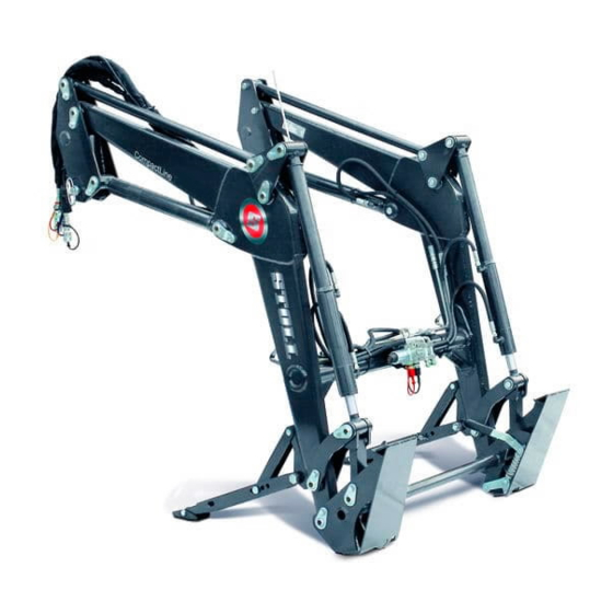
- Page 1 Operating instructions Front loader CompactLine Type FC: L, H, P Status: 12/2018 3483230 B58FC1 0000000094 EN 002...
- Page 2 Copyright © Wilhelm STOLL Maschinenfabrik GmbH Reproduction of these instructions, both completely and in excerpts, is only allowed with approval from Wilhelm STOLL Maschinenfabrik GmbH. Any infringement shall entail full compensation of damages and can be punishable by law. The original instructions were written in the German language.
-
Page 3: Table Of Contents
Contents About these operating instructions ........5 1.1 Documentation overview . - Page 4 6.1.3 STOLL Base Control ........
- Page 5 Servicing............77 8.1 Cleaning and care .
-
Page 6: About These Operating Instructions
Order the instructions through a dealer. Download instructions free of charge from the Internet at www.stoll-germany.com. Installation instructions for the front loader mounting kit The installation of the mounting kit as well as the hydraulic and electric equipment may only be performed by an authorised specialised workshop. -
Page 7: Use And Purpose Of The Operating Instructions
Validity of the operating Instructions The operating instructions are valid only for the STOLL front loader CompactLine, called "front loader" in the following or "L", "H" or "P" as the special versions. The front loader type can be found on the rating plate. -
Page 8: Other Applicable Documents
ABOUT THESE OPERATING INSTRUCTIONS Other applicable documents In conjunction with these operating instructions, the following additional documents also apply: Operating instructions of the tractor Operating instructions for the respective implements Installation instructions for the respective mounting kit and front loader additional equipment When handling the front loader and for all service work, please also observe: ... -
Page 9: Nomenclature Of The Footer
ABOUT THESE OPERATING INSTRUCTIONS Moreover, stylised drawings are used. For better understanding, some of the figures are exemplary, simplified or with dismounted parts for better representation and explanation. Please observe the following: Dismounting is not always absolutely required for the respective description. ... -
Page 10: Safety
Immediate lethal danger or serious injuries. ⚠ WARNING Possible lethal danger or serious injuries. ⚠ CAUTION Possible slight injuries. NOTICE Damage to the implement or the surroundings. EC Conformity STOLL front loaders comply with Machine Directive 2006/42/EC. B58FC1 0000000094 EN 002... -
Page 11: Proper Use
The CompactLine front loader is a mounted implement for agricultural and forestry tractors and is designed and intended solely for: Mounting on tractors with the front loader mounting kit approved by STOLL (see 3.6 Attaching it to the tractor), ... -
Page 12: Basic Safety Information
SAFETY Basic safety information The basic safety information comprises all safety measures grouped by theme and is applicable at all times. In addition, the information is presented as warning notices at the correspoding positions in these operating instructions. Basic dangers Mortal danger exists when persons are lifted or carried with the front loader. - Page 13 SAFETY Hydraulic dangers There is a risk of injury due to escaping hydraulic fluids under high pressure. Observe the safety stickers on the machine. Check the hydraulic couplings and lines for leaks before uncoupling. On tractors without a closed driver’s cab, mount tubes with splash guards. There is a risk of crushing when machine parts move uncontrollably due to entrapped air in the hydraulic system.
- Page 14 SAFETY Dangers during packaging and transport There is a risk of injury due to crushing, impacts or pinching if the front loader tips over or falls from the lifting gear. During all preparatory work, always ensure a secure stand of the machine. ...
- Page 15 SAFETY Dangers when picking up and putting down implements There is a risk of serious injury and lethal danger due to implements falling down or uncontrolled lowering of the front loader when unsuitable implements are used or if the used implements are overloaded. ...
- Page 16 SAFETY Dangers when operating the front loader There is a risk of serious injury or lethal danger due to tipping of the tractor when working on slopes, when going around bends, when the load on the rear axle is too low, and when driving into the bulk to be lifted at a skewed angle.
- Page 17 SAFETY Dangers due to falling loads There is mortal danger due to raised loads falling down on the driver's seat. There is a particularly high risk when lifting pallets or bales above the driver's cab and when working on slopes. Even the standard protection systems (roll-over protection structure ROPS, falling objects protective structures FOPS) do not provide fully adequate protection.
-
Page 18: Danger Zones
SAFETY Danger zones On and around the front loader, there are the following areas with increased risk to safety of the operator or safety of other persons: B081 Fig. 3 Top view (from above) Legend Work area (yellow) Outer danger zones (hatched in orange) Inner danger zones (red) Danger zone Description... -
Page 19: Adhesive Safety Label
SAFETY 2.10 Adhesive safety label Safety stickers warn of hazards at danger points and are an important part of the safety equipment of the front loader. Clean safety stickers if they are soiled. Replace damaged or illegible safety stickers (see 10.1 Spare parts). ... - Page 20 SAFETY Description of the safety sticker The numbering corresponds to the positions on the front loader (see Position of the safety sticker on the front loader). 3449070c B05T Fig. 5 Safety sticker B58FC1 0000000094 EN 002...
- Page 21 SAFETY Position Description Re-tighten all the fixing screws on the mounting kit after the first 5 hours of operation. Do not stand under the raised front loader. Do not stack several loads on top of each other. Only use suitable implement to prevent the load from falling down. Increased risk of tilting when the front loader is raised.
-
Page 22: Personnel Requirements
SAFETY 2.11 Personnel requirements In the operating instructions, a distinction is made between the following persons: Operators Qualified personnel Specialised tradesmen All person groups must have read and understood the operating instructions. The table lists the other respective qualifications and responsibilities. -
Page 23: Behaviour In Case Of Emergency
SAFETY 2.12 Behaviour in case of emergency Initiate the following measures to avoid further damage in cases of emergency: (1) Secure the accident site correctly. (2) Provide first aid (if necessary). (3) Call rescue workers, describe the situation briefly and concisely. Wait for feedback. (4) Inform the employer or operator. -
Page 24: Structure
STRUCTURE Structure Structure of L front loaders L front loaders are composed of the following main components: B0A2 Fig. 6 L front loader (exemplary figure) Legend Pillars (drive-in system) Lifting arm (base frame) Implement cylinder: hydraulic cylinder for dumping and scooping Hydraulic tubes Cross tube Implement (e.g. -
Page 25: Structure Of H Front Loaders
STRUCTURE Structure of H front loaders H front loaders are composed of the following main components: B0A3 Fig. 7 H front loader (exemplary figure) Legend Pillars (drive-in system) Lifting arm (base frame) Implement cylinder: hydraulic cylinder for dumping and scooping Hydraulic tubes Cross tube Lever mechanism dumping/scooping... -
Page 26: Structure Of P Front Loaders
STRUCTURE Structure of P front loaders P front loaders are composed of the following main components: B0A4 Fig. 8 Front loader P (exemplary figure) Legend Pillars (drive-in system) Lifting arm (base frame) Control rod of the parallel motion Deviation triangle of the parallel motion Implement cylinder: hydraulic cylinder for dumping and scooping Hydraulic tubes Cross tube... -
Page 27: Structure Of Additional Equipment For L, H, And P Front Loaders
STRUCTURE Structure of additional equipment for L, H, and P front loaders The additional equipment for L, H, and P front loaders consists of the following components: B0A5 Fig. 9 Additional equipment for L, H, and P front loaders (exemplary figure) Legend Hydraulic valve for the 3rd control circuit Socket for electrical connection to the 4th control circuit (on the implement) -
Page 28: Equipment Variations
STRUCTURE Equipment variations The table shows the different equipment variations for L, H and P front loaders: Equipment Front loader Basic equipment Parallel motion (mechanical) ─ ─ ● Change frame Skid-Steer ─ ● ● Euro ─ ○ ○ Implement locking mechanism mechanical ─... -
Page 29: Attaching It To The Tractor
STRUCTURE Attaching it to the tractor The front loader is attached to the tractor using the mounting kit for tractors. The mounting kit consists of the following components: B0A6 Fig. 10 Mounting kit for tractors Legend Front guard left and right Mounting parts left and right Mountings/catch hooks The components remain permanently mounted on the tractor. -
Page 30: Skid-Steer Change Frame
STRUCTURE 3.7.1 Skid-steer change frame These change frames are installed on FC 150-550 H and P front loaders. The change frames are intended for mounting implements complying with the Skid-steer standard. The implement cylinder serves to swivel the change frame around its pivot point. B0A7 Fig. -
Page 31: Hydraulic Lines
STRUCTURE Hydraulic lines ⚠ CAUTION There is a risk of injury due to escaping hydraulic fluids! If the hydraulic lines are not depressurized before the coupling procedures, oil can spray out and injure the skin or other body parts (e.g. eyes). ... -
Page 32: Hydraulic Couplings
STRUCTURE Hydraulic couplings 3.9.1 Plug-in couplings The bushings of the plug-in couplings are located on the hydraulic lines of the front loader. The plugs for the plug-in couplings can be found on the right-side mounting part for the tractor. They are connected to the hydraulic valve either directly or with hose lines. -
Page 33: Functions
FUNCTIONS Functions Implement locking mechanism 4.1.1 Mechanical implement locking mechanism Skid-steer and Euro change frames ⚠ WARNING Risk of injury due to implements falling down! The implement may fall down if the implement locking mechanism is open or not locked correctly. This can cause serious injury to persons standing in the surrounding area. - Page 34 FUNCTIONS Skid-steer change frame The mechanical implement locking mechanism on skid-steer change frames is actuated manually. To attach implements, the edge of the mounting surfaces is pushed into the mounting on the implement. As soon as the implement is resting on the change frame, the locking mechanism is closed with the lever.
-
Page 35: Basic Functions
FUNCTIONS Euro change frame The mechanical implement locking mechanism on Euro change frames is actuated manually. The implement is hinged with its hooks on the hook catch on the change frame. At the bottom, the implement is resting on the stop of the change frame. - Page 36 FUNCTIONS Lifting The 2 lifting cylinders are extended and thus raise the lifting arm and the implement. Without parallel motion, the angle between the lifting arm and the implement remains constant so that the implement changes its orientation. With parallel motion, the angle between the lifting arm and the implement changes so that the implement maintains its original orientation.
- Page 37 FUNCTIONS Scooping The 2 implement cylinders are retracted and thus swivel the implement upwards. The implement scoops. B0AE Fig. 21 Scooping function Legend Implement cylinders on the left and right Implement Dumping The 2 implement cylinders are extended and thus swivel the implement downwards.
-
Page 38: Float Position
FUNCTIONS Float position ⚠ WARNING Possible risk of injury due to unexpected movement! If the front loader is not completely lowered, a vacuum may form in the hydraulic cylinders during the float position. This causes uncontrolled lowering of the front loader at a later time. This can cause persons to be injured or crushed. -
Page 39: Indicator For Implement Position (Only H And P)
FUNCTIONS Indicator for implement position (only H and P) The indicator for the implement position is located on the right implement cylinder. It allows the horizontal position of the implement to be read from the driver's seat. The rod is attached on the lower bearing pin and runs through the lug that is attached to the deflection triangle or the lifting arm. -
Page 40: Anti-Lowering Guard
FUNCTIONS Anti-lowering guard ⚠ WARNING Risk of injury and accident due to implement tipping off! The anti-lowering guard only prevents the front loader from lowering, however, it does not prevent accidental dumping of the implement. Persons whose presence is required near the load can be injured by the load falling down. - Page 41 FUNCTIONS 3rd control circuit With a switch valve for the 3rd control circuit, hydraulic implement functions are enabled, e.g. the actuation of a top loading grip. The 3rd control circuit is actuated using button A on the operating lever (see 6.1.2 Tractor's own operating lever).
-
Page 42: Comfort Drive
FUNCTIONS 4.7.2 Comfort Drive ⚠ WARNING Possible risk of crushing! The front loader is lowered when the Comfort Drive is switched on. Before switching on the Comfort Drive, lower the front loader completely to the ground. NOTICE Possible material damage due to overloading! The Comfort Drive can be overloaded when working with heavy loads (e.g. -
Page 43: Start-Up
START-UP Start-up Initial operation The initial operation is executed at a specialised workshop. This also includes mounting of the front loader as well as a functional check. Obtain instruction from the specialised workshop and ask questions if necessary. Read the operating instructions before initial use. -
Page 44: Preparations
START-UP Preparations 5.3.1 Preparations on the tractor NOTICE Material damage due to divided brakes on the tractor! When the front loader is mounted, one-sided braking can lead to serious damage. Couple the brake pedal in the tractor before using the front loader. The divided brake pedal serve to support the steering of the tractor and can brake the respective wheels on each side. -
Page 45: Ballasting
START-UP 5.3.2 Ballasting ⚠ WARNING Serious injury due to the machine falling over! When working with the front loader without rear counterweights, the tractor can tip over and cause injury to the driver and persons in the surroundings. Moreover, there is the risk of overloading the front axle of the tractor. - Page 46 START-UP The formula to precisely determine the rear weight is specified in DIN EN 12525:2000-A2: Weight of the tractor in kg (incl. front loader and change frame without counterweight) Weight of the counterweight in kg Weight of the implement in kg (incl.
-
Page 47: Mounting The Front Loader
START-UP Mounting the front loader ⚠ WARNING Risk of injury due to uncontrolled movements! Uncontrolled movements of the front loader can cause injury to persons assisting in the surrounding area. Only mount the front loader when nobody is standing in the danger area (see 2.8 Danger zones). ... - Page 48 START-UP (3) Switch off the tractor. Apply the parking brake. Stop the engine. Depressurize the hydraulic system. To do so, move all of the operating levers to the end position. (4) Connect the hydraulic lines of the front loader (see 3.9 Hydraulic couplings).
-
Page 49: Aligning The Front Loader For Mounting
START-UP Aligning the front loader for mounting NOTICE Material damage due to abrupt operation! When aligning the front loader, abrupt movements can cause damage to the front loader and the mountings. Before mounting the front loader, check that the operating lever moves smoothly. ... -
Page 50: Operation
OPERATION Operation Operating elements 6.1.1 Basic controls with levers ⚠ WARNING Possible risk of injury due to uncontrolled movement of the front loader! If the control unit was not actuated for a longer period of time, there may be e.g. temperature differences between the hydraulic fluid and the control unit. - Page 51 OPERATION Depending on the equipment of the tractor, different operating levers can be installed for the front loader. In most cases, it is a cross lever or a joystick. On some tractors, there are 2 operating levers for the control of the front loader. The figures show a top view of the assignment for one operating lever (see Fig.
-
Page 52: Tractor's Own Operating Lever
OPERATION 6.1.2 Tractor's own operating lever ⚠ WARNING Risk of injury due to unexpected movement of the front loader! The front loader can move unexpectedly as a result of unintentional actuation of the operating lever or by programmed sequences. This can cause injury to persons in the surrounding area. ... -
Page 53: Stoll Base Control
Before using the front loader, immobilise or disconnect other implements on the tractor. Immobilise or disconnect the front loader before using other implements. The STOLL "Base Control" operating lever is a single-lever control unit with up to 3 push-button... - Page 54 OPERATION Locking and unlocking the operating lever in zero position Locking the operating lever: (1) Move the operating lever to the zero setting. (2) Push in the locking bolt. The red mark on the bolt is no longer visible. ...
-
Page 55: Operating The Parking Supports
OPERATION Operating the parking supports ⚠ CAUTION Risk of crushing by swivelling components! When swivelling in the parking supports, limbs can be crushed. When folding up the parking supports, do not reach between them and the lifting arm bar. The parking supports serve to safely put down the front loader. -
Page 56: Operating The Hydraulic Couplings
OPERATION Operating the hydraulic couplings 6.3.1 Operating the plug-in coupling Connecting plugs with couplings: (1) Remove the caps and wipe the coupling if necessary. (2) Insert the connector in the couplings. (3) Stick the caps together to prevent soiling. The plug-in couplings are connected. Disconnecting the plugs from the couplings: (1) Pull out the plugs from the couplings. - Page 57 OPERATION Functional principle of the skid-steer change frame locking mechanism The locking procedure consists of 3 phases: (1) Locking mechanism open The actuation lever is swivelled down up to the stop (horizontal position). The locking hook is pull up far enough so that it no longer protrudes down through the change frame.
- Page 58 OPERATION Opening the implement locking mechanism: (1) Move the actuation lever towards the tractor. (2) Move the actuation lever further down, causing the locking hook to be pulled up. The implement locking mechanism is open. Closing the implement locking mechanism: (1) Move the actuation lever up, causing the locking hook to be pressed down.
- Page 59 OPERATION Checking the implement locking mechanism (functional check) Lower front loader close to the ground and actuate the dumping function. Press the implement with the tip on the ground. When locked correctly, the implement remains on the change frame. ...
-
Page 60: Operating The Mechanical Implement Locking Mechanism On Euro Change
OPERATION 6.4.2 Operating the mechanical implement locking mechanism on Euro change frames ⚠ WARNING Risk of injury due to implements falling down! The implement may fall down if the implement locking mechanism is open or not locked correctly. This can cause serious injury to persons standing in the surrounding area. ... -
Page 61: Picking Up And Putting Down The Implement
OPERATION Checking the implement locking mechanism (functional check) Lower front loader close to the ground and actuate the dumping function. Press the implement with the tip on the ground. When locked correctly, the implement remains on the change frame. ... -
Page 62: Picking Up Implements With Mechanical Implement Locking Mechanism On Skid
OPERATION 6.5.1 Picking up implements with mechanical implement locking mechanism on skid-steer change frames ⚠ WARNING Risk of injury due to implements falling down! The implement may fall down if the implement locking mechanism is open or not locked correctly. This can cause serious injury to persons standing in the surrounding area. - Page 63 OPERATION (3) Use the dumping function until the change frame is swivelled out about half the way. Use the lowering function until the implement support of the change frame is slightly lower than the mounting pockets of the implement. B0AX Fig.
-
Page 64: Change Frames
OPERATION (10) If applicable, connect the hydraulic lines of the implement with the front loader couplings. Lower the front loader until the implement is level on the ground. Depressurize the hydraulic system. With the implement function actuated, move the operating lever in the lateral end positions in order to depressurize the B0AZ implement hydraulic system (see... - Page 65 OPERATION (2) Drive up close to the implement. (3) Use the dumping function until the change frame is swivelled out about half the way. Use the lowering function until the hook catch of the change frame is slightly lower than the hooks on the implement. B0B1 Fig.
-
Page 66: Picking Up Implements With Manual Pinon Implement Locking Mechanism
OPERATION (10) If applicable, connect the hydraulic lines of the implement with the front loader couplings. Lower the front loader until the implement is level on the ground. Depressurize the hydraulic system. With the implement function actuated, move the operating lever in the lateral end positions in order to depressurize the B0AZ implement hydraulic system... - Page 67 OPERATION (5) Connect the implement to the front loader in the bottom pin holes. Insert the pins in the pin holes from the outside. If the holes of the implement and front loader are not exactly congruent, align the implement precisely with the help of another person.
-
Page 68: Putting Down Implements With Mechanical Implement Locking Mechanism On
OPERATION (8) If applicable, connect the hydraulic lines of the implement with the front loader couplings. Lower the front loader until the implement is level on the ground. Depressurize the hydraulic system. With the implement function actuated, move the operating lever in the lateral end positions in order to depressurize the B0AZ implement hydraulic system... - Page 69 OPERATION (6) Unhook the change frame from the implement hooks. Use the dumping function until the implement support of the change frame is underneath the mounting pockets of the implement. B0BH Fig. 72 Unhooking the change frame (7) Slowly drive the tractor away in reverse. (8) If applicable, cover the implement with a protective tarp.
-
Page 70: Putting Down Implements With Manual Pinon Implement Locking Mechanism
OPERATION 6.5.5 Putting down implements with manual PinON implement locking mechanism ⚠ CAUTION Risk of crushing due to hydraulic cylinders swivelling down! Pulling out the pin from the hydraulic cylinder and the implements causes the hydraulic cylinder to fall on the front loader bar due to its own weight. As a result, this can crush hands and fingers. ... -
Page 71: Levelling In Reverse
OPERATION (5) Disconnect the implement from the front loader in the bottom pin holes. Remove the screw with circlip from the pin. Pull out the pin. (6) Switch on the tractor. (7) Slowly drive the tractor away in reverse. (8) If applicable, cover the implement with a protective tarp. -
Page 72: Driving On Roads
OPERATION Driving on roads ⚠ WARNING Serious risk of accidents and injury due to loads falling down! When driving on roads, serious accidents and injuries can be inflicted on other road users due to loads falling down. Only drive on roads without a load. ⚠... -
Page 73: Activating And Deactivating The Road Operation Lock
STOLL Base Control To activate the road operation lock: (1) Lock the operating lever (see 6.1.3 STOLL Base Control) in the zero position. The road operation lock is activated. Accidental actuation of the front loader is no longer possible. -
Page 74: Parking The Tractor With The Front Loader
OPERATION Parking the tractor with the front loader ⚠ WARNING Possible risk of injury due to lowering of the front loader! The front loader is lowered over time by the drop in pressure in the hydraulic system. This can result in damage and accidents. -
Page 75: Troubleshooting
If these points do not resolve the problem, the following table will help to localize and correct the fault. Incorrect repairs can lead to safety risks. That is why the repair work must only be carried out by suitably qualified personnel! STOLL recommends that the repair work be performed at a specialised workshop. B58FC1 0000000094 EN 002... - Page 76 TROUBLESHOOTING Description of the fault Cause Rectifying the fault It is difficult to move the operating Bowden cables are stiff. Check the attachment and routing of the lever (stiff). Bowden cables and if they are stuck anywhere. If necessary, oil or replace the Bowden cables.
- Page 77 TROUBLESHOOTING Description of the fault Cause Rectifying the fault Front loader, implement and Coupling not completely closed. Check the hydraulic coupling. implement with hydraulic function The coupling is defective. Replace the defective coupling halves. is blocked during lifting or lowering Hydro-Fix, multi-coupler and Implement- Check the locking lever for deformation.
-
Page 78: Servicing
SERVICING Servicing ⚠ WARNING Serious risk of injury due to uncontrolled lowering of the front loader! During service and repair work, a raised front loader can be lowered unexpectedly and crush and injure nearby persons. Only perform maintenance work when the front loader is completely lowered. ⚠... -
Page 79: Cleaning And Care
SERVICING Cleaning and care NOTICE Possible material damage due to unsuitable cleaning agents! Unsuitable cleaning agents can damage surfaces and safety devices as well as destroy seals. Only use cleaning agents that are compatible with the machine surfaces and seal materials. Clean the front loader with water and a mild cleaning agent. - Page 80 SERVICING Lubrication points on L, H and P front loaders The L front loader has 6 lubrication points on each side: B0B6 Fig. 79 L lubrication points The H front loader has 8 lubrication points on each side: B0B7 Fig. 80 Lubrication points on the H B58FC1 0000000094 EN 002...
-
Page 81: Lubrication Schedule
SERVICING The P front loader has 11 lubrication points on each side: B0B8 Fig. 81 Lubrication points on the P 8.1.2 Lubrication schedule Lubrication point Interval Lubricant [operating hours] Bearing positions 20 h Multipurpose grease DIN 51502 K2K, ISO 6743 ISO-L-XCCEA2, or comparable product Front loader mountings (catch hooks) 100 h Front loader locking mechanism... -
Page 82: Service Schedule
SERVICING 8.2.1 Service schedule The specified service intervals are guidelines. Adjust the intervals according to the operating conditions. Consult with a workshop for any questions. Interval Maintenance position [operating hours] Check the screw connections Check, tighten if necessary (see 11.3 Tightening torque for 100 h screws) Bearing positions... -
Page 83: Service Instructions For Oil Changes
SERVICING 8.2.4 Service instructions for oil changes The front loader is supplied by the oil circulation of the tractor. Observe the oil change intervals specified for the tractor. Before performing an oil change, lower the front loader onto the ground. ... -
Page 84: Decommissioning
DECOMMISSIONING Decommissioning Temporary decommissioning ⚠ WARNING Risk of injury due to lacking stability! If the front loader is not correctly and safely parked, it can tip over and injure persons nearby. Only park the front loader with a mounted implement that weighs at least 70 kg. ... -
Page 85: Recommissioning
DECOMMISSIONING (12) Drive the tractor in reverse out of the front loader. (13) Replace the protective caps on the hydraulic couplings and plugs. (14) If applicable, put the protective tarp over the front loader. The front loader is dismounted. B0BK Fig. -
Page 86: Spare Parts And Customer Service
The use of non-approved spare parts can impair the safety of the front loader and results in expiry of the operating permit. Only use original spare parts or those approved by STOLL. Original spare parts and fitting accessories are listed in separate spare part lists. -
Page 87: Technical Specifications
TECHNICAL SPECIFICATIONS Technical specifications 11.1 Dimensions and weights Front loader Nominal width Lifting arm length Nominal lifting force Weight [mm] [mm] Bottom [daN] [daN] [kg] FC 150 L 1400 FC 150 H 1400 FC 150 P 1400 FC 250 L 1590 FC 250 H 1590... -
Page 88: Tightening Torque For Screws
TECHNICAL SPECIFICATIONS 11.3 Tightening torque for screws Tightening torque for screws Strength category Thread 10.9 12.9 lb-ft lb-ft lb-ft M8x1 M10x1.25 M12x1.5 M12x1.25 M14x1.5 M16x1.5 M18x2 M18x1.5 M20x2 M20x1.5 M22x2 M22x1.5 1022 1017 1190 M24x2 1095 1282 1176 1496 1103 1750 1291 M27x2... -
Page 89: Hydraulic Diagram Fc
TECHNICAL SPECIFICATIONS 11.4 Hydraulic diagram FC F1 + F2 F1 + F2 B0B9 Fig. 86 Hydraulic diagram FC Legend Front loader Implement 4th control circuit (optional) 3rd control circuit (optional) Comfort Drive (optional) Tractor pressure Ignition Left Right B58FC1 0000000094 EN 002... -
Page 90: Electric Circuit Diagram
TECHNICAL SPECIFICATIONS 11.5 Electric circuit diagram NOTICE Material damage due to improper tensioning or lacking fuse! If the rated voltage of 12 V is exceeded or the ignition lock is not switched, the system can be damaged. Switch the rated voltage of 12 V via the ignition lock. ... -
Page 91: Arrangement Of The Hydraulic Valves For Additional Functions
TECHNICAL SPECIFICATIONS 11.6 Arrangement of the hydraulic valves for additional functions Fig. 88 shows the arrangement of the hydraulic valves for the additional functions Q1 to Q2 on the cross tube of the front loader or on the implement. The maximum equipment for L, H and P front loaders is shown. -
Page 92: Declaration Of Conformity
Directive 2014/68/EU on the provision of pressure equipment on the market. The technical documentation was produced according to Annexe VII A of Directive 2006/42/EC, and is the responsibility of the development manager at Wilhelm STOLL Maschinenfabrik GmbH, Bahnhofstrasse 21, D-38268 Lengede. - Page 93 DECLARATION OF CONFORMITY The design and manufacturing of the front loader observed the following harmonised standards that are also published in the EU official gazette: Harmonised Date Title of the standard standards DIN EN ISO 4254-1 2011-05 Agricultural machinery – Safety – Part 1: General requirements DIN EN ISO 4413 2011-04 Hydraulic fluid power –...
-
Page 94: Index
INDEX Index 3rd control circuit ..... 40 Faults ....... 74 Float position.. - Page 95 INDEX rating plate ......6 Recommissioning .....84 Repairs ......77, 82 Safety and warning notices ..
- Page 96 Address of the dealer Stick or write down the serial number here Wilhelm STOLL Maschinenfabrik GmbH STOLL on the Internet: PO box 1181, 38266 Lengede www.stoll-germany.com Bahnhofstr. 21, 38268 Lengede www.facebook.com\STOLLFrontloader Phone: +49 (0) 53 44/20 0 www.youtube.com\STOLLFrontloader Fax: +49 (0) 53 44/20 182 E-mail: info@stoll-germany.com...
Need help?
Do you have a question about the CompactLine FC Series and is the answer not in the manual?
Questions and answers