
Related Manuals for dooch N747D

Summary of Contents for dooch N747D
- Page 1 BOOSTER PUMP SYSTEM N747D User’s Manual For Booster Pump N747D Controller DOOCH CO., LTD BOOSTER PUMP SYSTEM...
-
Page 2: Table Of Contents
BOOSTER PUMP SYSTEM N747D Contents Chapter #1 The composition and features of controller Features of controller …………………… Major Functions of controller ………… Composition of controller ……………… Chapter #2 Key operation of user Key operation of user setting …….. Display of user setting ……….. - Page 3 BOOSTER PUMP SYSTEM N747D Chapter #5 Key operation of test operation Test operation key .…………………….. 46 Chapter #6 Other Keys Inverter reset Key …….…………………….. Key of Initial display ….…………………….. Alarm display and Reaction…………………. 49 Chapter #7 Appendix Control Board Arrangement and Description…. 52 Check items ………..………………………...
-
Page 4: Chapter #1
BOOSTER PUMP SYSTEM N747D Chapter #1 The composition and features of controller Features of controller Functions of controller Composition of controller Features of controller BOOSTER PUMP SYSTEM... -
Page 5: Major Functions Of Controller
BOOSTER PUMP SYSTEM N747D This advanced computer control device has been achieved its controlling of pump’s RPM by inverter through the newest electronic technology, and equipped with presumptive terminal pressure control technology and various intelligent functions which can determine and control the pressure of water supply according to the amount of supplied water and usage. -
Page 6: Composition Of Controller
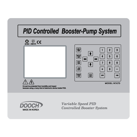
BOOSTER PUMP SYSTEM N747D Major function Description Inverter-fix type Select inverter-fix type from menu. LCD Monitor Displaying variety information through large LCD screen. LCD Display in Korean Easy operation and control for anyone by Korean menu. Select display language Select Korean(default) / English/ Chinese/ Spanish from menu. - Page 7 BOOSTER PUMP SYSTEM N747D < Controller External > Controller is consisted of LCD play and operation Keys. - LCD Display : It displays system information. - Operation Key : It is for data setting and checkup data. : It is for booster system user.
- Page 8 BOOSTER PUMP SYSTEM N747D : + , - Setting value. : It is for saving setting value and checking operation history/ alarm history : It is for deleting operation history/alarm history : It is for moving cursor to the menu.
-
Page 9: Chapter #2
BOOSTER PUMP SYSTEM N747D Chapter #2 Key operation of user Key operation of user setting Display of user setting Change of user setting(1) Change of user setting(2) Change of user setting(3) BOOSTER PUMP SYSTEM... - Page 10 BOOSTER PUMP SYSTEM N747D Key operation of user setting Display of user setting User setup display [1] User setup display [2] User setup display [3] - The display of User setup [3] is related with User setup [2] BOOSTER PUMP SYSTEM...
- Page 11 BOOSTER PUMP SYSTEM N747D < Display of Monthly operation> < Display of weekly operation> < Display of timely operation > 3. The change of user setup[1] 1. Press installer setup on main display 2. Input password and save (initial password is “0000”)
- Page 12 BOOSTER PUMP SYSTEM N747D 3. In user setup [1], move to desire display with cursor. 4.Move to desire display with cursor ※ Cursor can be moved to left / right. 5. Setting value can be changed by figure Keys. BOOSTER PUMP SYSTEM...
- Page 13 BOOSTER PUMP SYSTEM N747D 6. After setting, press “save” . The adjustable items in the user setting [1] are as below. - Setting pressure: Target water pressure to operate. Change of predetermined pressure. (Example: In case current set value is 03.00 kgf/cm²...
- Page 14 BOOSTER PUMP SYSTEM N747D - Step operational pressure(Emergent operational pressure) : When “step operation 1” has been set by user or inverter error occurs, pump runs if “setting pressure-current pressure” is lower than specified emergent operating pressure. Change of step operational pressure.
- Page 15 BOOSTER PUMP SYSTEM N747D 4. The change of user setup[2] 1. . Press user setup on main display. 2. . Input password and save (initial password is “0000”) 3. Press user setup key on user setting [1]. BOOSTER PUMP SYSTEM...
- Page 16 BOOSTER PUMP SYSTEM N747D 4. In user setup [2], move to desire display with cursor. 5. Setting value can be changed by figure Keys. BOOSTER PUMP SYSTEM...
- Page 17 BOOSTER PUMP SYSTEM N747D 6. After setting, press “save”. Changeable items in user setting [2] are as below. - Time setting : 2008/11/13 12:20 Thursday It displays in the order of year/month/day time :minute days, and if it does not matched with present time then adjust it.
- Page 18 5. To use scheduled operation, the settings shall be changed in “ user operation [3]. Refer to the changes in “user operation [3]” for detail information. - Change of user password : N747D is designed to set password in order to prevent others from tampering settings without authorization. Initial password is set as 0000.
- Page 19 BOOSTER PUMP SYSTEM N747D 5. The change of user setup[3] 1. Press user setup on main display. 2. . Input password and save (initial password is “0000”) 3. Press user setup key on user setting [1]. BOOSTER PUMP SYSTEM...
- Page 20 BOOSTER PUMP SYSTEM N747D 4. In user setup [2], move to schedule setup with cursor. 5. Choose desire figure from “0” to “3”. 0 : Not used 1 : Monthly operation 2 : Weekly operation 3 : Timely operation 6. After changing to operation setup, make sure to press Key.
- Page 21 BOOSTER PUMP SYSTEM N747D 7. After pressing Key, press user setup to move user setup [3]. 8. In user setup[3], choose desire menu with cursor.. BOOSTER PUMP SYSTEM...
- Page 22 BOOSTER PUMP SYSTEM N747D 10. Change the desire value with figure Keys. 11. After changing to operation setup, make sure to press Key. Set value is not changed until input key is pressed BOOSTER PUMP SYSTEM...
- Page 23 BOOSTER PUMP SYSTEM N747D Changeable items in user settings [3] as below. - Monthly scheduled operation. : Any operation by monthly can be scheduled and executed. To change settings, select monthly operation from the scheduled operation in “user setting [2] using Key, then press ‘user setting button’...
- Page 24 BOOSTER PUMP SYSTEM N747D Scheduled operation by time frame. : Any operation by time frame can be scheduled and executed. To change settings, select by-time frame operation from the scheduled operation in “user setting [2] using Key, then press ‘user setting button’ to move to “user setting [3] and change it.
-
Page 25: Chapter #3 Key Operation Of Installer
BOOSTER PUMP SYSTEM N747D Chapter #3 Key operation of installer Key operation of installer setting Display of user setting Change of installer setting(1) Change of installer setting(2) Change of installer setting(3) BOOSTER PUMP SYSTEM... - Page 26 BOOSTER PUMP SYSTEM N747D 1. Installer Setup Key 2. Display of Installer setup Display of installer setup[1] Display of installer setup[2] Display of installer setup[[3] BOOSTER PUMP SYSTEM...
- Page 27 BOOSTER PUMP SYSTEM N747D 3. The change of installer setup[1] 1. Press ENG SET key on main display. 2. . Input password and save (initial password is “0000”)) 3. In installer setup [2], move to desire item with cursor. BOOSTER PUMP SYSTEM...
- Page 28 BOOSTER PUMP SYSTEM N747D 5. Setting value can be changed by figure Keys. 6. After changing to operation setup, make sure to press Key. Set value is not changed until input key is pressed. BOOSTER PUMP SYSTEM...
- Page 29 BOOSTER PUMP SYSTEM N747D Changeable items in user settings [1] as below. - The minimum operation rate of inverter Set the minimum inverter output in %. When inverter operates, set 60Hz at 100%, or set value is 50% then operate from 30Hz.
- Page 30 BOOSTER PUMP SYSTEM N747D - Constant of differential ( D ) : : It is a constant of differential in PID control variables. Range : 1 ~ 100 Change of constant of differential ( I ) settings. (Example: In case of to change 10 to 1.
- Page 31 BOOSTER PUMP SYSTEM N747D 3. Enter in order of 2, 0 and 0 using Key. 4. After changing to required value, make sure to press Key. ※ Set value is not changed until input key is pressed. - Corrected value of sensor : This function corrects the deviation between the...
- Page 32 BOOSTER PUMP SYSTEM N747D 4. The change of installer setup[2] 1. Press ENG SET key on main display. 2. Input password and save (initial password is “0000”) 3. Press ENG SET on installer setup[1]. BOOSTER PUMP SYSTEM...
- Page 33 BOOSTER PUMP SYSTEM N747D 4. In installer setup [2], move to desire item with. 6. Setting value can be changed by figure Keys. BOOSTER PUMP SYSTEM...
- Page 34 BOOSTER PUMP SYSTEM N747D 7. After changing to operation setup, make sure to press Key. Set value is not changed until input key is pressed. The changeable items in installer setting [2] are as below; - Pump maximum pressure : Entering the maximum pressure of pump.
- Page 35 BOOSTER PUMP SYSTEM N747D - Setting of installer’s password : Changing installer’s password. Change of installer’s password (Example: To change “Installer’s password : 0000" to “User’s password:1234”) 1. Using Key, select 2. User’s password : Initially the first ‘0’ of the ’000’ blinks.
- Page 36 BOOSTER PUMP SYSTEM N747D 5. The change of installer setup[3] 1. Press ENG SET key on main display . 2. . Input password and save (initial password is “0000”). 3. Press ENG SET on installer setup[1]. BOOSTER PUMP SYSTEM...
- Page 37 BOOSTER PUMP SYSTEM N747D 4. Press ENG SET on installer setup[2]. 5. In installer setup [3], move to desire item with cursor.. 6. Setting value can be changed by figure Keys. BOOSTER PUMP SYSTEM...
- Page 38 BOOSTER PUMP SYSTEM N747D 7. After changing to operation setup, make sure to press Key. Set value is not changed until input key is pressed. The changeable items in user setting [3] are as below; - RS485 : Select whether to use RS485communication or not.
- Page 39 BOOSTER PUMP SYSTEM N747D Change setting of BAUD RATE (Example: In case of to change 9600bps to 1200bps) 1. Using Key, select 2. Using Key, select communication speed to be changed.. : 1200bps, : 2400bps, : 4800bps, : 9600bps, 19200bps 3.
- Page 40 BOOSTER PUMP SYSTEM N747D - CAN : Select whether to use CAN communication or not. Change CAN setting CAN . (Example: To change “No use” to “Use” ) 1. Using Key, select. CAN : NOT USED 2. Enter using Key.
-
Page 41: Confirmation Of Pump Operation History
BOOSTER PUMP SYSTEM N747D Chapter #4 Operation History Key 1. Confirmation of pump operation history Confirmation of alarm history BOOSTER PUMP SYSTEM... - Page 42 BOOSTER PUMP SYSTEM N747D Confirmation of pump operation history 1. Press operation Data key on main display. 2. In operation data, move to desire menu with cursor. BOOSTER PUMP SYSTEM...
- Page 43 BOOSTER PUMP SYSTEM N747D 3. It shows pump operation history. If you want to delete all pump operation history, press Del key. 2. Confirmaton of alarm history 1. Press operation Data key on main display 2. Press operation data key on operation data display.
- Page 44 BOOSTER PUMP SYSTEM N747D 3. In alarm history display, move to desire menu with cursor 5. It display alarm history. - It shows latest 10 alarm history.. - If you want to delete all alarm history, press DEL key. BOOSTER PUMP SYSTEM...
- Page 45 BOOSTER PUMP SYSTEM N747D Chapter #5 Test Operation Keys of test operation BOOSTER PUMP SYSTEM...
-
Page 46: Test Operation Key
BOOSTER PUMP SYSTEM N747D Test Operation Key It is used for checking direction of motor rotation. After turning off the STOP/START switch on panel, please operate this function. 1. Press Test Run key on main display.. 2. In the test run display, Choose desire pump with cursors. - Page 47 BOOSTER PUMP SYSTEM N747D 3. Use left/right cursor to select pump operation method. 4. Using Key, change the sensor correction value and Min operation ratio. BOOSTER PUMP SYSTEM...
-
Page 48: Chapter #6 Other Keys
BOOSTER PUMP SYSTEM N747D Chapter #6 Other Keys BOOSTER PUMP SYSTEM... -
Page 49: Inverter Reset Key
BOOSTER PUMP SYSTEM N747D 1. Inverter reset Key Key is used to re-start inverter in inverter error state. Up to 2 sets of inverters can be used, and pressing Key resets the inverter in trouble among two inverters (Two inverters are optional) 2. - Page 50 BOOSTER PUMP SYSTEM N747D If automatic operation is not available under low pressure alarming, please take one of below means. Set one of the front panel switch of pump 1, pump 2, pump 3, pump 4, pump 5 and pump 6( if there are 6 pumps) as MANU, so that one pump can be started and increases the pressure up to the low alarm setting pressure.
- Page 51 BOOSTER PUMP SYSTEM N747D Chapter #7 Appendix 1. Control board arrangement and description 2. Check items Procedure and manual for pump test operation Emergent operation 5. RS-485 communication BOOSTER PUMP SYSTEM...
-
Page 52: Control Board Arrangement And Description
BOOSTER PUMP SYSTEM N747D 1.Control board arrangement and description BOOSTER PUMP SYSTEM... - Page 53 BOOSTER PUMP SYSTEM N747D Main Board Error lamp relay C contact EMST System emergency operation signal terminal Error lamp relay A contact System start/stop signal terminal Sysetm error relay C contact S1NT Pressure sensor1 (-) terminal Sysetm error relay A contact...
- Page 54 BOOSTER PUMP SYSTEM N747D Inverter option board Pump option board Inverter pump relacy A contact I1RT Inverter 1 opertation recognition terminal Inverter pump relacy C contact Inverter 1 frequency setup current(4~20mA) pump relay A contact IENA Inverter 1 pump relay A contact...
-
Page 55: Check Items
BOOSTER PUMP SYSTEM N747D 2. Check items 1. No operation is started when powered ON; ⑴ Check power voltage (208V~440V). ⑵ Check power, wire short and contact terminals. 2. When powered ON, only LCD Back Light is turned on; ⑴ Turn VR counterclockwise with PIN driver. - Page 56 BOOSTER PUMP SYSTEM N747D 8. MC does not work in each pump;. ⑴ Check if each MC power is 220 V. ⑵ Verify shortages and contact points of 1. IPA, 2. IPC, 3. DPA and 4. DPC wire in Pump-OPT.
-
Page 57: Pump Test Operation
BOOSTER PUMP SYSTEM N747D 17. Auto-operation is not available in low pressure alarming; ⑴ Set the pressure time of low pressure alarm more than 10 seconds, then stop the front panel “START/STOP” switch and re-start. ⑵ Set one of the front panel switch of pump 1, pump 2, pump 3 and pump 4 as MANU, so that one pump can be started and increases the pressure up to the low alarm setting pressure. -
Page 58: Emergency Operation
BOOSTER PUMP SYSTEM N747D Remove all air by opening air cocks of inlet and pump, until water is dispensed only. Close air cocks. Turn on all internal NFB (breaker) of panel. Turn on the power switch of the panel front. - Page 59 BOOSTER PUMP SYSTEM N747D Set starting deviation pressure value becomes the condition of pump starting when operation mode is switched to emergent automatic operation. Setting of starting deviation pressure is available, however its initial value is set as 0.5bar. In this case, if set pressure is 4.0 bar, then sequential auxiliary pump starts if it’s not above 3.5bar.
- Page 60 BOOSTER PUMP SYSTEM N747D Operation of ON-OFF control method is carried on by Max/Min set value of pressure switch. As it is under control of controller, general functions such as shift operation can be carried out. Also water is supplied continuously, however, the pipe pressure is little bit unstable than RPM control due to the characteristics of ON/OFF of pressure switch.
- Page 61 BOOSTER PUMP SYSTEM N747D Communication Protocol ModBus- RTU Protocol Function code Code Name 0x03 Read Hold Register 0x06 Preset Single Register READ - Query (example) - response Single Write - Query (example - Pressure 5.5bar) - response Setting for communication...
- Page 62 -BAUD RATE -DELAY TIME -DRIVE MODE Diagnosis Check Points Remark Refer Page 53 Main board Check connection of N747D and equipment 11.485- 485 signal low 12.GND 485 Ground 13.485+ 485 signal high Refer Page 38 Check whether RS485 is use or not...
- Page 63 BOOSTER PUMP SYSTEM N747D Low Byte Bit 0: 1 Bit 1: 2 Bit 2: 3 Bit 3: 4 0x4003 Pump Bit 4: 5 Bit 5: 6 Bit 6: OPTION 0:Inverter(Fix) 1:Inverter(Move) 0x4004 Operation method 2:Sequential operation 1 3:Sequential operation 2...
- Page 64 BOOSTER PUMP SYSTEM N747D Address Parameter Scale Unit Content Pump4 trip 0x4017 0~65535 number -ber Pump5 trip 0x4018 0~65535 number -ber Pump6 trip 0x4019 0~65535 number -ber Pump1 operation 0x401A hour 0~65535 time Pump2 operation 0x401B hour 0~65535 time Pump3 operation...
- Page 65 BOOSTER PUMP SYSTEM N747D Content for each pump Low Byte : Trip content Bit 0 : High pressure Bit 1: Low pressure Bit 2: Pump over current Bit 3: Inverter1 Bit 4: Low level Bit 5: Sensor Current trip 0x4022...
Need help?
Do you have a question about the N747D and is the answer not in the manual?
Questions and answers