
Subscribe to Our Youtube Channel
Related Manuals for Bacci Twin

Summary of Contents for Bacci Twin
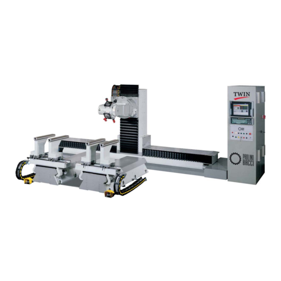
- Page 1 MACHINING CENTER Mod.: TWIN Use and maintenance instruction manual (translation of original instructions) Document: MAN_ TWIN1213R0en Edition: 12/2013 Rev.: 0 Data: 16/12/2013...
- Page 2 TWIN – Use and maintenance instruction manual Instruction manual for the machine models and the versions listed below. MACHINE MODELS AND VERSIONS DESCRIBED IN THE MANUAL MODEL DESCRIPTION Cap. 0 - II/...
- Page 3 GENERAL INDEX General index Foreword Safety information Machine description and technical data Installation Controls and use Maintenance Attached documents and diagrams Cap. 0 - III/...
- Page 4 TWIN – Use and maintenance instruction manual “Page intentionally left blank” Cap. 0 - IV/...
- Page 5 CHAPTER 1 – Foreword CHAPTER 1 Foreword Chap. 1 14 -...
-
Page 6: Table Of Contents
TWIN – Use and maintenance instruction manual INDEX Foreword ........................1 Objective of the manual ........................... 4 Manual addressees ........................... 5 1.2.1 Description of symbols, deadlines and abbreviations adopted ..............7 ... -
Page 7: Foreword
CHAPTER 1 – Foreword “Page intentionally left blank” Chap. 1 14 -... -
Page 8: Objective Of The Manual
TWIN – Use and maintenance instruction manual 1.1 Objective of the manual As foreseen in the Machinery Directive 2006/42/EC, this manual provides information on safety and the life phases of the machine (transport, installation, use, maintenance, dismantling). Read carefully and understand this technical publication before intervening at operational level on the machine or performing adjustment and/or maintenance interventions. -
Page 9: Manual Addressees
CHAPTER 1 – Foreword 1.2 Manual addressees All operations described will be accompanied by a symbol (pictograph) corresponding to the operator considered more suitable for the task; the symbols at the head of each paragraph correspond to the addresses of the information provided. Please find below the instructions necessary for the identification of the different professional figures. - Page 10 TWIN – Use and maintenance instruction manual Certain pieces of information of the manual may address non-professional figures (e.g. cleaning personnel of the premises where the machine is installed) who are not authorised to operate the machine, but may be close to the premises for different reasons.
-
Page 11: Description Of Symbols, Deadlines And Abbreviations Adopted
CHAPTER 1 – Foreword 1.2.1 Description of symbols, deadlines and abbreviations adopted For optimum machine use, we recommend you are familiar with the terms and symbols contained in the manual. 1.2.2 Symbols adopted, glossary of terms and illustrations Information addressees Refer to paragraph “1.2 Addressees of the manual”... - Page 12 TWIN – Use and maintenance instruction manual INFORMATION! The colours of the photos shown this manual illustrating the machine's structure or constituting parts may differ from the ones installed on your machine. Remember that the content of this manual refers to technically comparable machines that represent the machine...
-
Page 13: Glossary Of Safety Terms
CHAPTER 1 – Foreword 1.3 Glossary of safety terms In compliance with European Directives 89/391/EEC, 89/654/EEC, 89/655/EEC, 89/656/EEC, 90/269/EEC, 90/270/EEC, 90/394/EEC, 90/679/EEC, 93/88/EEC, 95/63/EEC, 97/42/EEC, 98/24/EEC, 99/38/EEC and 2001/45/V concerning the improvement of workers’ safety and health during work, please find below the definitions used in this instruction manual. PERSONAL PROTECTIVE EQUIPMENT (PPE) Personal protective equipment (PPE) is equipment worn by the operator to minimize exposure to a variety of safety and health hazards at work, as well as any complement or accessory serving the same... -
Page 14: Use And Conservation Of Documentation
Paolino Bacci S.r.L. reserves the right to modify the characteristics of the product and content of this manual without prior notice. Paolino Bacci S.r.L. reserves the right to provide a soft copy of the manual. The publication on file is in PDF (Portable Document File) format; for consultation you need to set up the Adobe® Acrobat®... -
Page 15: How To Request Additional Copies
CHAPTER 1 – Foreword 1.6 How to request additional copies Further copies of this document apart from the contractual ones are available upon request by sending a regular purchase order to Paolino Bacci S.r.L.. 1.7 Manufacturer’s Identification and Contact Details Company name: Paolino Bacci S.r.l. -
Page 16: Customer Service
TWIN – Use and maintenance instruction manual 1.8 Customer service To guarantee our customers optimum use of the product purchased, Paolino Bacci S.r.L. provides the following technical support services: Customer service: Office services provided by qualified operators, who are able to diagnose and decide upon the interventions required to restore damaged and malfunctioning machinery components. -
Page 17: How To Request Spare Parts
You must use original spare parts. The replacement of parts with non-original parts or parts that have not been previously authorised by Paolino Bacci S.r.L. is at the customer's own risk and shall result in the immediate expiry of the warranty and of the certification pursuant to applicable community directives. - Page 18 TWIN – Use and maintenance instruction manual “Page intentionally left blank” Chap. 1 - 14 14 -...
-
Page 19: Safety Information
CHAPTER 2 – Safety information CHAPTER 2 Safety information Chap. 2 52 -... - Page 20 TWIN – Use and maintenance instruction manual INDEX Safety information ....................... 1 Qualification of personnel ........................4 General safety rules ..........................5 Use of Personl protective equipment (PPE) ..................7 ...
- Page 21 CHAPTER 2 – Safety information 2.16.9.1 TANDEM processing cycle - (Risk ID: 13.01) ............... 47 2.16.10 Residual risks during HOLD-TO-RUN movements (portable control) ............48 2.16.10.1 HOLD-TO-RUN movements (portable control) – (Risk ID: 15.01) ........48 ...
-
Page 22: Qualification Of Personnel
TWIN – Use and maintenance instruction manual 2.1 Qualification of personnel This manual provides instructions on use and maintenance, lists the hazards and residual risks of the machine but does not take into account the risks of the work environment and the specific work modalities of the company using the machine. -
Page 23: General Safety Rules
CHAPTER 2 – Safety information 2.2 General safety rules A series of general rules for correct machine use are provided here following; these rules must be integrated with the specific operating procedures. It is up to the purchaser: • to conduct a risk evaluation of the machine concerning the characteristics of the installation environment and those of the company working modalities, assess and understand the residual risks included in the manual in order to take the necessary safety measures (Personl protective devices, working procedures etc.). - Page 24 TWIN – Use and maintenance instruction manual Maintenance personnel is required to: • Implement a correct machine maintenance timetable. • Check the state of the machine on a daily basis and immediately replace parts that are worn or damaged. •...
-
Page 25: Use Of Personl Protective Equipment (Ppe)
CHAPTER 2 – Safety information 2.3 Use of Personl protective equipment (PPE) If the use of Personl protective equipment (PPE) is required according to the manual or signs/warnings on the machine, remember that the choice of the most suitable type for the level of protection required is up to the employer. -
Page 26: Minimum Equipment
TWIN – Use and maintenance instruction manual Symbol Explanation You are obliged to use a shield protector. You are obliged to use a respiratory facial mask (facemask for covering the nose and nostrils). You are obliged to use hearing protection devices (earplugs or earmuffs). -
Page 27: Safety And Warning Sings
CHAPTER 2 – Safety information Safety and warning sings 2.4.1 Description of hazard images DANGER IMAGES 1 of 4 SYMBOL DESCRIPTION OF HAZARD INDICATIONS/WARNINGS If manual equipment is used, take care to prevent cuts and shears. Follow the safety Cutting, shearing provisions and wear the appropriate PPE (safety gloves against general risks). - Page 28 TWIN – Use and maintenance instruction manual DANGER IMAGES 2 of 4 SYMBOL DESCRIPTION OF HAZARD INDICATIONS/WARNINGS Keep a safe distance from the indicated zones to prevent lower limb crushing. Crushing of lower limbs Watch out for all movements of the unit where the image is located.
- Page 29 CHAPTER 2 – Safety information DANGER IMAGES 3 of 4 SYMBOL DESCRIPTION OF HAZARD INDICATIONS/WARNINGS Follow the safety provisions and adopt the Hazards generated by noise for appropriate PPE (ear safety devices or values above 80 Db soundproof headsets). Corrosive agents Corrosive agents Irritating agents Irritating agents...
- Page 30 TWIN – Use and maintenance instruction manual DANGER IMAGES 4 of 4 SYMBOL DESCRIPTION OF HAZARD INDICATIONS/WARNINGS Be careful near the indicated zones. Keep a safe distance to prevent the injection of fluids under Injection of pressurised fluids pressure (pneumatic or hydraulic system). Follow the safety provisions and wear the appropriate PPE (safety screen).
-
Page 31: Description Of Prohibition Images
CHAPTER 2 – Safety information 2.4.2 Description of prohibition images PROHIBITION IMAGES 1 of 1 SYMBOL DESCRIPTION INDICATIONS No access to unauthorised personnel. Access prohibited Follow the safety provisions. It is forbidden to work without guards or protection with exposed chains, gears or moving components. -
Page 32: Description Of Obligation Symbols
TWIN – Use and maintenance instruction manual 2.4.3 Description of obligation symbols OBLIGATION IMAGES 1 of 1 DESCRIPTION INDICATIONS SYMBOL It is mandatory to disconnect and isolate Obligation of disconnection and the sources of energy before starting isolation of the sources of energy. -
Page 33: Location Of Information And Warnings On The Machine
CHAPTER 2 – Safety information 2.4.5 Location of information and warnings on the machine Ref. SYMBOL INFORMATION / WARNING LOCATION AP01 Keep at a safe distance in order to Electrical boards, control avoid hazards deriving from direct or panels indirect contact with life parts or instruments. -
Page 34: Envisaged Use
TWIN – Use and maintenance instruction manual 2.5 Envisaged use Envisaged use means use of the machine in conformity with the information provided in the user instructions. The machine may be used only by professional operators who are trained and informed as to the contents of this instructions manual. -
Page 35: Reasonably Foreseeable Incorrect Use
Reasonably foreseeable incorrect use means use of the machine in a manner that differs from that specified in the user instructions but that may derive from easily foreseeable human conduct. The experience of the manufacturer, PAOLINO BACCI s.r.l. permits signaling out the following examples of incorrect use machine use:... -
Page 36: Information On The Work Environment
TWIN – Use and maintenance instruction manual D) ALTERATIONS The following cases are considered incorrect uses: • Altering the machine in any way that alters the envisaged use of the machine. 2.7 Information on the work environment The machine has been constructed to operate in closed, well ventilated environments that are full of light. -
Page 37: Noise Hazards Typical Of The Wood Industry
CHAPTER 2 – Safety information 2.7.5 Noise hazards typical of the wood industry The wood processing industry is traditionally characterized by processes that create high noise exposure levels, due to a series of concomitant factors, such as the use of tools that have an elevated noise force concentrated in work environments that are often tight. -
Page 38: Safety Devices
TWIN – Use and maintenance instruction manual Safety devices This section contains information regarding the safety devices adopted to eliminate or reduce machine hazards. When a safety device does not fully eliminate a hazard and a reduced risk remains, this risk is described in the manual as a residual risk. - Page 39 CHAPTER 2 – Safety information DEVICE TYPE / FUCNTION PHOTO / NOTES REMOVABLE GUARD Each access door fitted with interlocking device and guard block. During Access door fitted with interlocking device and regular machine operation, the door is closed guard block. and blocked.
- Page 40 TWIN – Use and maintenance instruction manual DEVICE TYPE / FUCNTION PHOTO / NOTES HOLD-TO-RUN Only expert and authorised personnel may use the portable pushbutton panel. Hold-to-run pushbuttons located portable pushbutton panel. This pushbutton panel is used to manually control the movement of each axis, one at a time, while standing inside the all-around enclosure.
- Page 41 CHAPTER 2 – Safety information DEVICE TYPE / FUCNTION PHOTO / NOTES DUST EXTRACTION (PREPARATION) Connect the machine to a vacuum system whose characteristics are described in the The machine is ready to be connected to a technical data. vacuum system dust extraction device (not supplied).
-
Page 42: Safety Device Checks
TWIN – Use and maintenance instruction manual 2.8.1 Safety device checks NOTE: The checks described here below refer to the guards described in the preceding sections of the manual. 2.8.1.1 Emergency pushbutton check Once a year, check: Test A): impede machine start-up •... -
Page 43: Padlock Station, Clamps, Padlock Checks
Check that the padlocks and clamps to lock off and tag out energy supplies are always on hand. NOTE: padlocks and clamps are not supplied by the machine manufacturer Paolino Bacci S.r.l , and must be provided to operating personnel by the employer. -
Page 44: Machine Areas And Workstations
TWIN – Use and maintenance instruction manual Machine areas and workstations The machine is designed and manufactured considering use by only one operator, whose task it is to supply the machine for production and remove the machined product, as well as operate the manual controls, only after having verified that there are no exposed persons in the danger areas. -
Page 45: Identification Of Work Areas
CHAPTER 2 – Safety information 2.9.1 Identification of work areas The area around the main pushbutton panel and loading/unloading are the main operator work areas from which the operator may enable commands, program work cycles and check proper machine operation. For maintenance and to fit tools on the machine, the operator must also access the safety enclosure. -
Page 46: Warnings Regarding Conduct Inside The All-Around Enclosure
TWIN – Use and maintenance instruction manual 2.9.4 Warnings regarding conduct inside the all-around enclosure • Interventions inside the all-around enclosure must be carried out only by qualified technicians. Before carrying out this type of interventions, place a “MAINTENANCE UNDERWAY” sign on the machine. - Page 47 CHAPTER 2 – Safety information Operation / Function Task N. Description Stage Handling and transportation Maintenance work carried out by Transport, mechanical technicians and in part by installation and the machine operator (simple cleaning assembly and visual inspections). Various activities - inspection, Maintenance work carried out only by Maintenance cleaning, etc.
- Page 48 TWIN – Use and maintenance instruction manual Operation / Function Task N. Description Stage TANDEM processing cycle The processing occurs with the piece supported by both the support devices axes) that move synchronously. The tandem processing requires a machine setup by the...
-
Page 49: Safety Regulations For Spindle Use And Maintenance
CHAPTER 2 – Safety information 2.11 Safety regulations for spindle use and maintenance Before starting the spindles turning, it is essential to: • Check that the tools have been fitted only after the spindle seat has been cleaned. • Check that the tools are clamped tightly. •... -
Page 50: Safety Regulations For Programming
TWIN – Use and maintenance instruction manual 2.13 Safety regulations for programming Before starting any program, including automatic homing, we recommend making sure that the portable pad is enabled in order to be able to reduce speed and, if necessary, stop machine movements. - Page 51 Do not disconnect the yellow/green (earthing) safety wire or use it for other purposes. At the end of every maintenance intervention, check that it is functioning properly! • Use only original spare parts. P. Bacci S.r.l. is not liable for damage or malfunctions in case of the use of non-original electrical components. •...
-
Page 52: Safety Regulations For Pneumatic Maintenance
TWIN – Use and maintenance instruction manual 2.15 Safety regulations for pneumatic maintenance • Maintenance may be carried out only by qualified technicians. Before starting any type of maintenance, place a “MAINTENANCE UNDERWAY” warning sign on the machine, stop the machine and cut-off all electrical and pneumatic sources. -
Page 53: Residual Risks Present During Any Stage
CHAPTER 2 – Safety information 2.16.1 Residual risks present during any stage 2.16.1.1 Passing through or stationing near dangerous areas – (Risk ID: 00.01) IDENTIFICATION RISK ASSESSMENT Stage: Initial risk: HIGH Person: Common person Area: Z00 All areas RESIDUAL RISK: LOW PLr (EN 13849): - SIL (EN IEC 62061): - ACCIDENT SCENARIO... -
Page 54: Residual Risks During Normal Operation
TWIN – Use and maintenance instruction manual 2.16.2 Residual risks during normal operation 2.16.2.1 Normal operation – (Risk ID: 04.06) IDENTIFICATION RISK ASSESSMENT Stage: Initial risk: HIGH Person: Operator Area: Z03 Inside the machine RESIDUAL RISK: MEDIUM PLr (EN 13849): -... -
Page 55: Normal Operation - (Risk Id: 04.07)
CHAPTER 2 – Safety information 2.16.2.2 Normal operation – (Risk ID: 04.07) IDENTIFICATION RISK ASSESSMENT Stage: Initial risk: MEDIUM Person: Operator Area: Z02 Material loading/unloading area RESIDUAL RISK: MEDIUM PLr (EN 13849): - SIL (EN IEC 62061): - ACCIDENT SCENARIO Consequence: 7.1 Respiratory difficulties, suffocation 7.2 Cancer... -
Page 56: Residual Risks During Assembly/Disassembly
TWIN – Use and maintenance instruction manual 2.16.3 Residual risks during assembly/disassembly 2.16.3.1 Assembly/disassembly– (Risk ID: 06.01) IDENTIFICATION RISK ASSESSMENT Stage: Maintenance Initial risk: HIGH Person: Specialised technician Area: Z00 All areas RESIDUAL RISK: MEDIUM PLr (EN 13849): - SIL (EN IEC 62061): -... -
Page 57: Assembly/Disassembly- (Risk Id: 06.03)
CHAPTER 2 – Safety information 2.16.3.2 Assembly/disassembly– (Risk ID: 06.03) IDENTIFICATION RISK ASSESSMENT Stage: Maintenance Initial risk: HIGH Person: Specialised technician Area: Z00 All areas RESIDUAL RISK: MEDIUM PLr (EN 13849): - SIL (EN IEC 62061): - ACCIDENT SCENARIO Consequence: 1.3 Crushing 1.4 Cutting or shearing Situation:... -
Page 58: Residual Risks During Handling And Transportation
TWIN – Use and maintenance instruction manual 2.16.4 Residual risks during handling and transportation 2.16.4.1 Handling and transportation– (Risk ID: 07.01) IDENTIFICATION RISK ASSESSMENT Stage: Transportation, installation and assembly Initial risk: HIGH Person: Specialised technician Area: Z00 All areas RESIDUAL RISK: MEDIUM... -
Page 59: Residual Risks During Various Activities - Inspection, Cleaning, Etc
CHAPTER 2 – Safety information 2.16.5 Residual risks during various activities – inspection, cleaning, etc. 2.16.5.1 Various activities – inspection, cleaning, etc. – (Risk ID: 08.03) IDENTIFICATION RISK ASSESSMENT Stage: Maintenance Initial risk: MEDIUM Person: Operator Area: Z00 All areas RESIDUAL RISK: LOW PLr (EN 13849): SIL (EN IEC 62061):... -
Page 60: Residual Risks During Work On The Electrical System
TWIN – Use and maintenance instruction manual 2.16.6 Residual risks during work on the electrical system 2.16.6.1 Work on the electrical system – (Risk ID: 09.01) IDENTIFICATION RISK ASSESSMENT Stage: Maintenance Initial risk: HIGH Person: Maintenance personnel Area: Z01 Electrical equipment... -
Page 61: Work On The Electrical System - (Risk Id: 09.02)
CHAPTER 2 – Safety information 2.16.6.2 Work on the electrical system – (Risk ID: 09.02) IDENTIFICATION RISK ASSESSMENT Stage: Maintenance Initial risk: HIGH Person: Maintenance personnel Area: Z01 Electrical equipment RESIDUAL RISK: MEDIUM PLr (EN 13849): - SIL (EN IEC 62061): - ACCIDENT SCENARIO Consequence: 2.4 Electrocution... -
Page 62: Rischi Residui Presenti Durante Gli Interventi Di Lubrificazione/Ingrassaggio
TWIN – Use and maintenance instruction manual 2.16.7 Rischi residui presenti durante gli interventi di lubrificazione/ingrassaggio 2.16.7.1 Lubrication/greasing – (Risk ID: 11.01) IDENTIFICATION RISK ASSESSMENT Stage: Initial risk: MEDIUM Person: Maintenance personnel Area: Z00 All areas RESIDUAL RISK: LOW PLr (EN 13849): -... -
Page 63: Residual Risks During Single Pitch Loading/Unloading (Work Cycle)
CHAPTER 2 – Safety information 2.16.8 Residual risks during SINGLE PITCH loading/unloading (work cycle) 2.16.8.1 SINGLE PITCH loading/unloading (work cycle) – (Risk ID: 12.01) IDENTIFICATION RISK ASSESSMENT Stage: Initial risk: HIGH Person: Operator Area: Z02 Material loading/unloading area RESIDUAL RISK: LOW PLr (EN 13849): d SIL (EN IEC 62061): SIL2 ACCIDENT SCENARIO... -
Page 64: Single Pitch Loading/Unloading (Work Cycle) - (Risk Id: 12.02)
TWIN – Use and maintenance instruction manual 2.16.8.2 SINGLE PITCH loading/unloading (work cycle) – (Risk ID: 12.02) IDENTIFICATION RISK ASSESSMENT Stage: Initial risk: LOW Person: Operator Area: Z02 Material loading/unloading area RESIDUAL RISK: LOW PLr (EN 13849): - SIL (EN IEC 62061): -... -
Page 65: Residual Risks Existing In Tandem Processing Cycle
CHAPTER 2 – Safety information 2.16.9 Residual risks existing in TANDEM processing cycle 2.16.9.1 TANDEM processing cycle - (Risk ID: 13.01) IDENTIFICATION RISK ASSESSMENT Stage: Operation Initial risk: HIGH Person: Operator Area: Z02 material loading/unloading area Residual risk: AVERAGE PLr (EN 13849): - SIL (EN IEC 62061): - ACCIDENT SCENARIO Consequence:... -
Page 66: Residual Risks During Hold-To-Run Movements (Portable Control)
TWIN – Use and maintenance instruction manual 2.16.10 Residual risks during HOLD-TO-RUN movements (portable control) 2.16.10.1 HOLD-TO-RUN movements (portable control) – (Risk ID: 15.01) IDENTIFICATION RISK ASSESSMENT Stage: Maintenance Initial risk: HIGH Person: Maintenance personnel Area: Z05 Portable pushbutton control... -
Page 67: Residual Risks During Height Work
CHAPTER 2 – Safety information 2.16.11 Residual risks during height work 2.16.11.1 Height work – (Risk ID: 16.01) IDENTIFICATION RISK ASSESSMENT Stage: Maintenance Initial risk: HIGH Person: Maintenance personnel Area: Z00 All areas RESIDUAL RISK: MEDIUM PLr (EN 13849): - SIL (EN IEC 62061): - ACCIDENT SCENARIO Consequence:... -
Page 68: Residual Risks During Adjustments With Laser Devices
TWIN – Use and maintenance instruction manual 2.16.12 Residual risks during adjustments with laser devices 2.16.12.1 Adjustments with laser devices – (Risk ID: 17.01) IDENTIFICATION RISK ASSESSMENT Stage: Maintenance Initial risk: MEDIUM Person: Maintenance personnel RESIDUAL RISK: LOW Area: Z00 All areas... -
Page 69: Residual Risks Present During Safeguarding Work
CHAPTER 2 – Safety information 2.16.13 Residual risks present during safeguarding work 2.16.13.1 Safeguarding work– (Risk ID: 18.01) IDENTIFICATION RISK ASSESSMENT Stage: Initial risk: MEDIUM Person: Operator Area: Z03 Inside the machine RESIDUAL RISK: MEDIUM PLr (EN 13849): c SIL (EN IEC 62061): SIL1 ACCIDENT SCENARIO Consequence: 1.0 Various mechanical hazards... -
Page 70: Residual Risks During Interventions Of Telephone Support And Remote Assistance
TWIN – Use and maintenance instruction manual 2.16.14 Residual risks during interventions of telephone support and remote assistance 2.16.14.1 Telephone support and remote assistance interventions - (Risk ID: 19.01) IDENTIFICATION RISK ASSESSMENT Stage: Troubleshooting and repair Initial risk: AVERAGE Person:... - Page 71 CHAPTER 3 – Machine description and technical data CHAPTER 3 Machine description and technical data Chap. 3 /28 -...
- Page 72 TWIN – Use and maintenance instruction manual INDEX 3 Machine description and technical data ..................... 1 Description of machine functioning ..................... 3 Characteristics of machinable materials..................3 Maximum sizes of pieces to be loaded for machining ............... 4 ...
- Page 73 The oversized the beams allows for wide sideways movements of the heads (X axis). The elevated dynamics of the TWIN work station derives from the use of precision reducers with no backlash and that require no periodic adjustments, as well as from the perfect automatic lubrication "from the inside out".
- Page 74 Moreover, the minimum gripping intensity is different for each type of tool used. In any event, the manufacturer PAOLINO BACCI S.r.l. is available for further information. Possible machining The machining that may be carried out by the machine is described and shown below. Some of the types of machining shown below may be carried out only with the aid of optional machining units.
- Page 75 CHAPTER 3 – Machine description and technical data MACHINING FIGURE Flat surface milling within distance Vertical and horizontal milling 4/5 axis milling within distance Cutting Chap. 3 /28 -...
- Page 76 TWIN – Use and maintenance instruction manual Manufacturing features The machine is divided in two work stations. The control panel, located on one side of the machine, contains separate controls for each station. The machine is composed of the following main groups or units: •...
- Page 77 TABLE HEADS MACHINE BODY PIECE TRADENAME MOVABLE STRUT (X,Z) , HEAD (B,A) TABLE (Y1,Y2) TWIN The axes controlled by the machine are: • X axis • Transversal axes of the Y axis carriage • Vertical Z axes of the Z axis carriages •...
- Page 78 TWIN – Use and maintenance instruction manual All screws and skids are automatically lubricated from the CN and lubrication is checked along the line by a control sensor.The main units and optional units making up the machine are listed below POS.
- Page 79 CHAPTER 3 – Machine description and technical data Description of main units 3.7.1 Machine body (X-axis) The machine body is made up of a strongly ribbed, stabilized steel structure, of considerable section, to ensure maximum stiffness and straightness over time, under any load conditions. On the machine body, the strut sliding guides along the X-axis are mounted [1].
- Page 80 TWIN – Use and maintenance instruction manual All movements are controlled by brushless motors (no need for maintenance) and high-precision, preloaded-balls, recirculation screws that allow travel speed up to 100 m/min. The lubrication of all screws and shoes is automatic, numerically controlled and monitored by control sensors during the travel.
- Page 81 CHAPTER 3 – Machine description and technical data Type 4: It consists of four independent, coplanar electrospindles, each equipped with tool fitting and preset stop. Available versions: • 10,0 HP / ER 32 • 12,5 HP / ER 40 Type 4, Prismatic: It consists of four independent, coplanar, staggered electrospindles, each equipped with tool fitting and preset stop.
- Page 82 TWIN – Use and maintenance instruction manual Type 3+2: It consists of three independent, coplanar spindles, plus a double-exit electrospindles. All of them are equipped with tool fitting and preset stop. Available versions: • 10,0 HP / ER 32 •...
- Page 83 CHAPTER 3 – Machine description and technical data Whatever the head used, through the “Power Control” function, the NC slows down the speed of the axes when the absorbed power exceeds 160% of rated power. All the (high-power) electrospindles are driven by an electronic inverter, with rotating speed from 0 to 24.000 rpm, and 10 Hp power (18.000 rpm for higher power).
- Page 84 TWIN – Use and maintenance instruction manual 3.7.5 Spindle extension with ceramic bearings (OPTIONAL) For ER 32 or ER 40, it extends the spindle to 170 mm. Equipped with 2 pairs of angular-contact, ceramic bearings, 12.000 rpm max. It guarantees the same characteristics as the standard spindle.
- Page 85 “TGV” - Variable Geometry Tables (Y1 and Y2 axes) The TWIN work center is equipped with two independent work tables [1], that are numerically controlled and movable along the Y axis (height from the floor for loading/unloading = 1050 mm) for oversize processing and translation: in this way, the head can operate in conditions of maximum stiffness and therefore accurately.
- Page 86 TWIN – Use and maintenance instruction manual 3.7.8 Depression table (OPTIONAL) Made up of aluminum, variable size, 50 mm grid and equipped with lids and threaded holes, it can be mounted directly on the TGV or its supports, to facilitate locking of flat-base pieces, and for machining the upper side of the workpiece.
- Page 87 CHAPTER 3 – Machine description and technical data 3.7.11 Tilting TGV shelves (OPTIONAL) The tilting TGV shelves may be added to standard TGV tables (without TGV-TRC or TGV-CN), manually operated by means of a handwheel, equipped with a specific measuring siko, around the Y-axis (from 0°...
- Page 88 TWIN – Use and maintenance instruction manual 3.7.13 Standard workpiece locking The standard version of the machine is equipped with 4 pneumatic pressers (2 for each table) easily anchored to the shelves by means of dovetail guides, for optimal locking.
- Page 89 CHAPTER 3 – Machine description and technical data Suction cups of different sizes are also available. The cups are easily placed along the TGV arm, by means of the dovetails grooves. If necessary, the suction cups may also be equipped with a little lifting piston, to avoid scratching the workpiece.
- Page 90 TWIN – Use and maintenance instruction manual 3.7.15 Electrical cabinet The electrical cabinet contains the main controls and electronic equipment required to manage machine operations, including the numerical control CN (1) and the operator panel (2). The electrical cabinet in fitted with an air...
- Page 91 CHAPTER 3 – Machine description and technical data 3.7.17 Centralized grease lubrication system The centralized, automatic lubrication system is connected by means of progressive distributors to all the recirculating ball carriages and all the axis worm screw nuts. The system lubricates all the connected points at the preset greasing intervals, with the grease in the greasing tank (1).
- Page 92 TWIN – Use and maintenance instruction manual 3.7.18 Centralized grease lubrication system centralized, automatic lubrication system connected means progressive distributors recirculating ball skids and all the axis worm screw nuts. The system lubricates all the connected points based on the lubricating time settings, using the oil contained in the tank (1).
- Page 93 CHAPTER 3 – Machine description and technical data Technical data INFORMATION! The paragraphs that follow contain the main technical data for the machine, or in any event the minimum and maximum obtainable performance output; this data may differ based on specific customer requirements.
- Page 94 TWIN – Use and maintenance instruction manual 3.8.2 Machine electrical wiring data TYPE DESCRIPTION Electrical voltage in Volts See machine plate Electrical frequency in Hz See machine plate Electrical absorption in kW See machine plate Contemporaneity factor 3 phases + 1 earth...
- Page 95 CHAPTER 3 – Machine description and technical data 3.8.7 Spaces for use and maintenance INFORMATION! Space requirements for use and maintenance must be verified on the machine’s main installation layout drawing, which must always be consulted. The presence of structural elements such as, for example, walls, columns, etc., or work equipment in the area destined to machine use and maintenance may render proper installation impossible.
- Page 96 TWIN – Use and maintenance instruction manual Machine identification The machine and electrical board identification data are shown on the identification plates. The location of the identification plates is shown in the figure below. • The symbol is present only on the machine identification plate and only for machines marketed and sold within the European Community, accompanied by the relative EC declaration of conformity, as per annex II A of the Machinery Directive 98/37/CE.
- Page 97 S CONFORMANT TO ALL THE PROVISIONS OF IRECTIVES 2006/42/EC (M ACHINERY 2004/108/EC (EMC) DESIGNATES as person authorized to prepare the Technical File the company Paolino Bacci S.r.l., via Palermo 32 56021 CASCINA (PI) - Italy. ASCINA HE LEGAL REPRESENTATIVE ACCI Chap. 3...
- Page 98 TWIN – Use and maintenance instruction manual “Page intentionally left blank” Chap. 3 - 28 /28 -...
- Page 99 CHAPTER 4 – Installation CHAPTER 4 Installation Chap. 4 /20 -...
- Page 100 TWIN – Use and maintenance instruction manual INDEX Installation ........................1 Information required on handling of loads and installation ..............3 4.1.1 Loads handling equipment provided by the customer ................4 4.1.2 Installation equipment provided by the customer ..................
- Page 101 All operations described in the Installation chapter must be performed by qualified personnel authorized by PAOLINO BACCI S.r.l. Chap. 4 /20 -...
- Page 102 TWIN – Use and maintenance instruction manual 4.1.1 Loads handling equipment provided by the customer For handling loads and installing the machine it is necessary to have the equipment listed in the following tables. Upon receiving the machinery, unless otherwise agreed, all the material must be available in the installation site.
- Page 103 CHAPTER 4 – Installation 4.1.2 Installation equipment provided by the customer INSTALLATION EQUIPMENT 1 of 1 EQUIPMENT Extension leads Drill with drill bits Grinding wheel with disks for metal Welding machine 4.1.3 Installation preparations made by the customer The installation site must be equipped with the following: •...
- Page 104 TWIN – Use and maintenance instruction manual Packaging, handling, transport The following paragraphs provide the main information on the preparation of the machine for transport or shifting. Certain machine parts are actually disassembled before transport to facilitate handling or to reduce the maximum dimensions of the machine.
- Page 105 CHAPTER 4 – Installation • Before hoisting the load completely, always check that hoisting is aligned with the barycenter of the load being hoisted; if necessary, adjust the position of the hoisting equipment or redistribute the loads. • During horizontal movements, avoid pitching as much as possible, especially during movement start-up or stop.
- Page 106 The machine is shipped in perfect working conditions after having undergone general testing in our plant. Based on the type and size of the components to be shipped, P. Bacci will use appropriate packing to ensure the machine does is not damaged during shipment and up to delivery to the customer.
- Page 107 INFORMATION! In the event of damage or lack of certain parts, contact Paolino Bacci Srl to agree upon the procedures to adopt. Depending on the characteristics of the machine or its parts, different devices and materials are used to protect the machine or its parts during transport.
- Page 108 TWIN – Use and maintenance instruction manual PACKAGING PRECAUTIONS 2 of 2 TYPE DESCRIPTION COMPONENTS • Bags of anti-humidity salt are placed inside electrical switchboards and control panels. • When the machine is shipped in a container anti-humidity • salt is placed inside the barrier bag.
- Page 109 CHAPTER 4 – Installation 4.3 Preparing the machine for shipment 4.3.1 Disconnecting the electrical cabinet STEP ACTION DESCRIPTION • Before working on any machine circuit or component, it is OBLIGATORY to always verify that there is no residual voltage or pressure in the systems, making sure that work is carried out safely and Safety checks that all safety devices are in place and working.
- Page 110 TWIN – Use and maintenance instruction manual 4.3.2 Mechanical preparations for transport STEP ACTION DESCRIPTION • Before working on any machine circuit or component, it is OBLIGATORY to always verify that there is no residual voltage or pressure in the systems,...
- Page 111 CHAPTER 4 – Installation 4.4 Component and load group identification and handling Machine hoisting and handling equipment that must be provided by the end user customer are: • N. 1 crane. • N. 1 lift-truck. • Polyester hoisting straps. • 80 mm diameter hoisting pipes.
- Page 112 TWIN – Use and maintenance instruction manual TYPE OF HANDLING HOISTING • Some machine structures or the machine body may be hoisted using a crane, hooked up to the polyester straps (1) wound around the structures. • Position the straps on the external part of the structures to be hoisted (2), making sure they will not be crushed or come into contact with edges or corners that may damage them.
- Page 113 CHAPTER 4 – Installation TYPE OF HANDLING HOISTING • The machine’s electrical cabinet (6) has four eyebolts (7) located on the upper section of the cabinet to allow for hoisting using a specific hoisting device, such as, for example, a crane (1) and four ropes (2). •...
- Page 114 Transportation Take special care of over-sized machines shipped in OPEN TOP type containers. In these cases, Paolino Bacci S.r.l. will transport the load up to the ship. Unless otherwise agreed upon, the customer must organize and provide for road haulage from the port of destination to the installation site, choosing means of transport suited to the load to be transported.
- Page 115 CHAPTER 4 – Installation 4.6 Installation site requirements The site where the machine is to be positioned must meet certain requirements. The buyer is responsible for preparing the machine’s site of installation. 4.6.1 Floor specifications The site where the machine is to be positioned must meet certain requirements. The buyer is responsible for preparing the machine’s site of installation.
- Page 116 TECHNICAL DIAGRAMS AND GENERAL INFORMATION. Assembly The machine is assembled by Bacci technicians, as assembly may present risks for un-specialized personnel and requires specific and unique manufacturer know-how. The information provided in this manual provides a minimal description of the tasks to be carried out.
- Page 117 CHAPTER 4 – Installation STEP ACTION DESCRIPTION • Measure the levelness of the X axis by placing a precision level halfway Levelness along the length of the X axis ball screw or halfway along the length of one check of the X axis linear guides. •...
- Page 118 TWIN – Use and maintenance instruction manual 4.7.2 Removing safety guards and blocks used for transportation Once the machine has been anchored to the ground, remove all the safety guards and blocks used during transportation. Connection to power supplies The wires and cables between the machine and the electrical cabinet are removed for ease of transportation.
- Page 119 CHAPTER 5 – Controls and use CHAPTER 5 Controls and use Chap. 5 /48 -...
- Page 120 TWIN – Use and maintenance instruction manual INDEX Controls and use ......................1 Location of machine control panels ....................... 3 5.1.1 Main switch ..............................5 5.1.2 Main pushbutton panel ..........................6 ...
- Page 121 CHAPTER 5 – Controls and use Location of machine control panels The pushbutton panels on the machine and the control panel may be used to modify the various machine work parameters and/or control the machine. The controls located on the various machine control panels are described in this chapter.
- Page 122 TWIN – Use and maintenance instruction manual CONTROL LOCATION Portable pushbutton panel Located inside the machine’s all- around safety enclosure. It is connected to the electrical board by a cable that renders the panel portable. Table pushbutton panel Located near the loading/unloading area.
- Page 123 CHAPTER 5 – Controls and use 5.1.1 Main switch MAIN SWITCH POS. CONTROL DESCRIPTION Two-position main switch (0 – 1) Turn the switch to turn the machine on and off: • Main switch In the "0" position, the machine is off. •...
- Page 124 TWIN – Use and maintenance instruction manual 5.1.2 Main pushbutton panel CONTROLS ON THE MAIN PUSHBUTTON PANEL POS. CONTROL DESCRIPTION When the pilot light is on, the machine is connected. “Grid connected” pilot light When the pilot light is off, the machine is disconnected.
- Page 125 CHAPTER 5 – Controls and use CONTROLS ON THE MAIN PUSHBUTTON PANEL POS. CONTROL DESCRIPTION Use the key selector switch to select either manual or automatic operating mode. The 2 operating modes differ in terms of degree of operating safety. Manual operating mode is not as safe as automatic operating mode.
- Page 126 TWIN – Use and maintenance instruction manual CONTROLS ON THE MAIN PUSHBUTTON PANEL POS. CONTROL DESCRIPTION Press the RESET button to reset the machine after a stop. RESET pushbutton "Start automatic cycle" Press this pushbutton to start the machining program.
- Page 127 CHAPTER 5 – Controls and use 5.1.3 Portable pushbutton panel CONTROLS ON THE PORTABLE PUSHBUTTON PANEL POS. CONTROL DESCRIPTION When the pilot light is on, the pushbutton panel is enabled. “Pushbutton panel The panel may be enabled using the Soft key enabled”...
- Page 128 TWIN – Use and maintenance instruction manual CONTROLS ON THE PORTABLE PUSHBUTTON PANEL POS. CONTROL DESCRIPTION Press this control to move the axis as described on the control “Axis movement” control itself, either forwards or backwards. Only one axis may be moved pushbutton at a time, with a hold-to-run type action.
- Page 129 CHAPTER 5 – Controls and use 5.1.4 Table pushbutton panel CONTROLS IN THE TABLE PUSHBUTTON PANEL POS. CONTROL DESCRIPTION Stops the machine in emergency mode and turns off the machine. Disconnects power from axes and spindles Emergency Stop The pushbutton has a mechanical block that keeps it in position; Pushbutton turn it to the left to release.
- Page 130 TWIN – Use and maintenance instruction manual 5.1.5 Bench control foot pedal BENCH CONTROL FOOT PEDAL DESCRIPTION OF CONTROLS POS. CONTROL DESCRIPTION Use this control to select how the piece is blocked. • Manual mode: The piece is blocked: •...
- Page 131 CHAPTER 5 – Controls and use Operating procedures The sections that follow describe the operator tasks required for correct machine operation. We recommend designated personnel read and fully comprehend the instruction manual, particularly as regarding operating instructions and safety recommendations. Machine turn on and start up procedures First machine start-up must be carried out by our technical assistance personnel or by maintenance personnel duly trained and qualified to carry out the first start-up procedure.
- Page 132 TWIN – Use and maintenance instruction manual 5.3.1 Start-up procedure – preliminary operations STEP ACTION DESCRIPTION The following safety checks must be performed before beginning the start- up procedure: Safety checks • It is OBLIGATORY that the machine be run by only one authorized operator;...
- Page 133 CHAPTER 5 – Controls and use STEP ACTION DESCRIPTION Check the pneumatic supply air pressure. Initial regulation of pressure gauges: • Check that the pressure gauge for the balancing cylinders (2) shows a Check working pressure of 6 bar. pneumatic air supply If the pressure shown is not the working pressure, use the pressure pressure.
- Page 134 TWIN – Use and maintenance instruction manual 5.3.2 Start-up procedure – Turning on the machine STEP ACTION DESCRIPTION The following safety checks must be performed before beginning the start- up procedure: Safety checks • It is OBLIGATORY that the machine be run by only one authorized operator;...
- Page 135 CHAPTER 5 – Controls and use STEP ACTION DESCRIPTION Release any Emergency pushbuttons that have been pressed by pressing and turning the button to the left. Release emergency pushbuttons Press the "Reset" button. RESET • Press the “Turn on Auxiliaries" pushbutton (8). •...
- Page 136 TWIN – Use and maintenance instruction manual 5.3.3 Start-up procedure – Zeroing STEP ACTION DESCRIPTION The following safety checks must be performed before beginning the start- up procedure: Safety checks • It is OBLIGATORY that the machine be run by only one authorized operator;...
- Page 137 CHAPTER 5 – Controls and use STEP ACTION DESCRIPTION • Turn the "Overdrive" potentiometer (2) gradually to "0%" Zero potentiometer Zero all the axes using the control panel. From the Main Menu, press the ZEROING Softkey F. Zero axes Turn the "Overdrive" potentiometer gradually to 100%. potentiometer Chap.
- Page 138 TWIN – Use and maintenance instruction manual 5.3.4 Spindle pre-heating During the first daily start-up, and any time the spindles have cooled to room temperature, all the spindles must first run through a short heating cycle, to allow the bearings to gradually reach a uniform working temperature.
- Page 139 CHAPTER 5 – Controls and use Machine turn off procedure To turn off the machine, proceed as described following. STEP ACTION DESCRIPTION Press the "Reset" button. Machine Reset Press one of the Emergency pushbuttons located on the pushbutton panels. Emergency Pushbutton •...
- Page 140 TWIN – Use and maintenance instruction manual 5.4.1 Machine turn off procedure for more than two hours For machine stoppages longer than 2 hours, follow the procedure below. STEP ACTION DESCRIPTION Turn off the main cut-off valve (turn the knob counter-clockwise) and lock it.
- Page 141 CHAPTER 5 – Controls and use Machine stop and re-start The paragraphs below describe the procedures to be followed to stop the machine and interrupt or cut- off power supplies. In fact, there are three different types of machine stops that the user may execute to stop the machine running.
- Page 142 TWIN – Use and maintenance instruction manual 5.5.1 Stop and re-start procedure after an EMERGENCY In the event of a sudden machine stop, be it intentional or accidental, correct function re-start depends on how the machine has been stopped. Proceed as described following.
- Page 143 CHAPTER 5 – Controls and use STEP ACTION DESCRIPTION • If a person is in danger, press the emergency stop pushbutton on any control panel. • Activating the The emergency stop is a safety stop and has priority over all other controls; it command is not synchronized with the forward feed of the machined product, which may therefore become jammed in one or more points in the machine subsequent...
- Page 144 TWIN – Use and maintenance instruction manual 5.5.3 Stop and re-start procedure after working stop - RESET In the event of a sudden machine stop, be it intentional or accidental, correct function re-start depends on how the machine has been stopped.
- Page 145 CHAPTER 5 – Controls and use 5.5.4 Machine stop during machining If the machine has been stopped during a machining cycle, the operator must remove the spindle from the piece. NOTE Safety warning DANGER! Danger of collision between the spindle and the piece. Working procedures The sections that follow describe the operator tasks required for correct machine operation.
- Page 146 TWIN – Use and maintenance instruction manual 5.6.2 HOLD-TO-RUN movements (portable control) The machine may be used in “HOLD TO RUN” mode only by the operator designated to run the machine. • The operator must use the “HOLD TO RUN” mode only for operations that must be supervised closely.
- Page 147 CHAPTER 5 – Controls and use OPERATIONS IN MANUAL MODE USER DESCRIPTION The following tasks must be carried out with the machine in manual mode: • Machine equipping • Machine cleaning Maintenance personnel • Machine maintenance INFORMATION! Any other operation is forbidden in manual mode. 5.6.3 SINGLE PITCH loading/unloading (work cycle) The machine must be used by the operator or maintenance technician for normal...
- Page 148 TWIN – Use and maintenance instruction manual STEP DESCRIPTION Working cycle execution (CNC program). − Manual loading of the piece. − Low-pressure locking of the piece through the clamps, performed by the operator by means of the foot control. −...
- Page 149 CHAPTER 5 – Controls and use 5.6.4 TANDEM processing cycle The machine must be used by the operator or machine maintenance technician, for the normal processing procedures of the materials. STAGE DESCRIPTION Perform machine setup, by following the operations described in section “TANDEM processing cycle setup”.
- Page 150 TWIN – Use and maintenance instruction manual Equipping the machine Only the operator in charge of running the machine may carry out the tasks described in this chapter. This section contains all the information regarding machine equipping. This chapter is divided into two parts. The first part deals with the tool, including safety recommendations, tool choice, maintenance and presetting.
- Page 151 CHAPTER 5 – Controls and use NOTE DANGER! Cutting hazard Tool cutting edges are sharp and may cause: Safety warning • Cutting injuries • Puncture injuries. Handle tools with extreme care. Use the following personal protective equipment (PPE): metal mesh gloves , when replacing and handling tools.
- Page 152 TWIN – Use and maintenance instruction manual 5.7.4 Machine tool assembly information MAINTENANCE NOTE INFORMATION! Use only spacers that correspond to the diagram below: Machine maintenance information Chap. 5 - 34 /48 -...
- Page 153 CHAPTER 5 – Controls and use 5.7.5 Balancing machine tools Tools, tool holders and any spacers used must be dynamically balanced in G1. MAINTENANCE NOTE INFORMATION! Rebalance the tool and tool holder every time the tool is sharpened. Machine maintenance Improper tool balancing may lead to: information •...
- Page 154 TWIN – Use and maintenance instruction manual 5.7.6 Cleaning machine tools G Tools, tool holders and any spacers used must be dynamically balanced in G1. MAINTENANCE NOTE INFORMATION! Keep the following components rigorously clean: • Tapers • Shafts • Tool gripping clamps...
- Page 155 CHAPTER 5 – Controls and use 5.7.7 Loading and presetting tools To preset the tools, proceed as follows. STEP ACTION DESCRIPTION • Turn the working unit using the manual controls. Manual pushbutton control: A+ (15) movement pushbutton A- (16) movement pushbutton Positioning spindle head 1 The spindle to be equipped is positioned upwards.
- Page 156 TWIN – Use and maintenance instruction manual STEP ACTION DESCRIPTION • Turn the working unit using the manual controls. Manual pushbutton control: A+ (15) movement pushbutton A- (16) movement pushbutton Reposition the head The spindle to be equipped is positioned towards the work side.
- Page 157 CHAPTER 5 – Controls and use Setup of piece support devices and presser clamps 5.8.1 Adjusting the pressers The presser clamps may be adjusted in two ways: • In the first case, for example for a 50 mm piece, the clamps may be adjusted so that when they are closed the minimum space is 45 mm.
- Page 158 TWIN – Use and maintenance instruction manual 5.8.2 Setup sequence The setup sequence varies according to the type of workpiece support device mounted on the table. As the machine may use support equipment made up by the customer, the customer is required to adequately instruct the personnel responsible for machine operation about the specific workpiece support devices used for processing.
- Page 159 • Using the technical features of Paolino Bacci S.r.l. work centers, taking advantage of speed, accelerations and axis power, through the advanced machining path “jerk limitation” and “smoothing” functions, without compromising machine reliability and long service life.
- Page 160 TWIN – Use and maintenance instruction manual 5.11 Overview of the main PITAGORA functions The zoom function, the possibility of obtaining piece and machine pan views, enlarging them and rotating them during any step of the program realization process makes it possible to visually measure collisions and obtains a precise and reliable result.
- Page 161 CHAPTER 5 – Controls and use POS. DESCRIPTION Dialogue box to enter rapid coupling Dialogue box to enter the path and rapid feedrate 3D animation Automatic collision check Execution time for rapid coupling Dialogue box to enter ISO program File importing CN code entered Machining time Chap.
- Page 162 TWIN – Use and maintenance instruction manual POS. DESCRIPTION Windows® interface OpenGL® graphic interface Chap. 5 - 44 /48 -...
- Page 163 5.12 Telephone troubleshooting service Should the troubleshooting be difficult, it is possible to use the telephone troubleshooting service of the manufacturer, Paolino Bacci S.r.l. DANGER! During the telephone connection, the manufacturer’s technical department may ask the customer’s personnel to perform various operations on the machine, aimed at resolving the malfunctioning.
- Page 164 During the normal operation of the machine, the teleservice must be disconnected and deactivated. The teleservice connection is always initiated following a request made by the customer, and only after intervention safety and coordination between customer’s personnel and technical personnel of the manufacturer, Paolino Bacci S.r.l., has been organized. Chap. 5 - 46...
- Page 165 CHAPTER 5 – Controls and use TELESERVICE CONNECTION LOGICAL DIAGRAM Service INTRANET BACCI BACCI Linea telefonica, ISDN, ADSL HDSL INTERNET CLIENTI PC 1 Cliente A Connessione Ethernet INTRANET PC 2 Cliente Modem CLIENTE A Macchina A Connessione Ethernet Modem CLIENTE B...
- Page 166 TWIN – Use and maintenance instruction manual “Page intentionally left blank” Chap. 5 - 48 /48 -...
- Page 167 CHAPTER 6 – Maintenance CHAPTER 6 Maintenance Chap. 6 32 -...
- Page 168 TWIN Use and maintenance instruction manual INDEX Maintenance ........................ 1 Maintenance .............................. 3 Safety instructions............................ 4 6.2.1 Other interventions ............................. 5 Maintenance timetable ..........................6 6.3.1 Ordinary and extraordinary maintenance timetable ..................6 ...
- Page 169 (planned maintenance intervention). INFORMATION! Before carrying out any maintenance operation which is not described in this manual, or in case you have doubts on the information provided please contact Paolino Bacci S.r.L.. INFORMATION! • All planned mechanical and electrical maintenance operations must be correctly carried out according to the recommended timetable.
- Page 170 TWIN Use and maintenance instruction manual Safety instructions Maintenance may be carried out only by qualified personnel. Unless otherwise specified, all maintenance is to be carried out with the machine turned off. In particular, make sure that the main switch (see Chapter 5: Controls and Use) is in the “0” off position and that all residual air present in the pneumatic system has been vented using the cut-off valve (see Chapter 5: Turning the machine on and off).
- Page 171 If the need for maintenance and repair interventions that are not contained in this manual arises while you use the machine, you are recommended to address the Technical Support department of Paolino Bacci S.r.L. For telephone and fax contact details please refer to Chap 1 "Manufacturer’s Identification and Contact Details".
- Page 172 TWIN Use and maintenance instruction manual 6.3 Maintenance timetable 6.3.1 Ordinary and extraordinary maintenance timetable The table below contains all the machine maintenance requirements and specifies the maintenance intervals. Maintenance intervals are calculated considering a 5 day work week, each day being made up of 8 working hours, in normal working conditions.
- Page 173 CHAPTER 6 – Maintenance Personnel Interval – Product qualification – Frequency in Machine part / component Mechanical hours maintenance technician Pneumatic system: 1000 h • Visual inspection of tubes, couplings, etc. Mechanical parts: • Visual inspection of mechanical 1000 h components (guides, skids, bearing screws) and components subject to wear...
- Page 174 TWIN Use and maintenance instruction manual ORDINARY MAINTENANCE TIMETABLE – ELECTRICAL / ELECTRONIC MAINTENANCE TECHNICIAN Personnel Interval – Product qualification – Frequency in Machine part / component Mechanical hours support technician • Electrical cabinet air conditioner overhaul 10.000 h Electrical wiring: •...
- Page 175 CHAPTER 6 – Maintenance Greasing and lubrication 6.4.1 Useable oils and grease MAINTENANCE NOTE Risk of damage to the machine. Use only the recommended oils. Machine maintenance Other products may be incompatible with the product used by the manufacturer for first information lubricant top-up.
- Page 176 TWIN Use and maintenance instruction manual 6.4.1.1 Lubricant oil for the pneumatic system (FLR) For the FRL pneumatic system (1), use one of the products indicated in the table below or an ISO/UNI F class or ISO/UNI H class hydraulic oil.
- Page 177 CHAPTER 6 – Maintenance 6.4.1.1 Oil for the tool holders To lubricate the tapered part of the tool holders (1), use only the product specified in the table below. BRAND TYPE OF LUBRICANT METAFLUX Spray paste 70-81 Chap. 6 - 11 32 -...
- Page 178 TWIN Use and maintenance instruction manual 6.4.1.1 Oil for the centralized lubrication system For the centralized lubrication system (1), use oil that has the characteristics specified in the table below. Use one of the products indicated in the table below or an ISO/UNI F class or ISO/UNI H class hydraulic oil.
- Page 179 CHAPTER 6 – Maintenance 6.4.1.2 Greases for the centralized greasing system For the centralized greasing system (1), use grease that has the characteristics specified in the table below. TYPE OF GREASE NLGI-0 (or equivalent) NLGI-1 (or equivalent) MAINTENANCE NOTE Risk of damage to the machine. Use only grease that is resistant to high pressure, otherwise, if the oil soaps separate Machine inside the lubricant grease, they may then solidify and jam up the pneumatic system.
- Page 180 TWIN Use and maintenance instruction manual 6.4.1.3 Greases for mechanical elements/parts (manual lubrication) Use one of the products specified in the table below. TYPE OF GREASE NLGI-0 (or equivalent) NLGI-1 (or equivalent) SKF bearing grease MAINTENANCE NOTE Risk of damage to the machine.
- Page 181 CHAPTER 6 – Maintenance 6.4.2 Maintenance of the centralized lubrication system For detailed information regarding the maintenance of the centralized lubrication system, please consult the specific information contained in ANNEX E OEM DOCUMENTATION. Chap. 6 - 15 32 -...
- Page 182 TWIN Use and maintenance instruction manual 6.4.2.1 Automatic system check and topping-up AUTONOMOUS MAINTENANCE TIMETABLE – MONTHLY CLEANING – LUBRICANT LEVEL CHECK QUALIFICATION OF TYPE OF PERSONNEL MAINTENANCE MACHINE STATE MAINTENANCE REQUIRED PERSONNEL Check Operators 1 (one) MACHINE CUT-OFF MAINTENANCE MATERIALS AND EQUIPMENT •...
- Page 183 CHAPTER 6 – Maintenance MAINTENANCE NOTE INFORMATION! Machine • Risk of damage to the machine. maintenance information Use only one of the greases specified above. Other products may be incompatible with the product used by the manufacturer for initial greasing. Incompatible greases mixed together or used one after they other may create substances that are damaging for machine operation, thereby compromising machine safety.
- Page 184 TWIN Use and maintenance instruction manual 6.4.3 Maintenance of the centralized greasing system For detailed information regarding the maintenance of the centralized greasing system, please consult the specific information contained in ANNEX E OEM DOCUMENTATION NOTE DANGER! Safety Risk of the spring flying off warning There is a highly loaded spring (1) inside the tank (see plate 2).
- Page 185 CHAPTER 6 – Maintenance 6.4.3.1 Automatic system check and topping up AUTONOMOUS MAINTENANCE TIMETABLE – MONTHLY CLEANING – LUBRICANT LEVEL CHECK QUALIFICATION OF TYPE OF PERSONNEL MAINTENANCE MACHINE STATE MAINTENANCE REQUIRED PERSONNEL Check Operators 1 (one) MACHINE CUT-OFF MAINTENANCE EQUIPMENT AND MATERIALS •...
- Page 186 TWIN Use and maintenance instruction manual STEP ACTION DESCRIPTION Use clean lubricant as foreign bodies may clog the pump filter. Topping up the tank Connect the pneumatic filling to the centralized system coupling point. Connect the system Fill the tank to the “maximum level” mark.
- Page 187 CHAPTER 6 – Maintenance MAINTENANCE NOTE INFORMATION! • Risk of damage to the machine. Machine maintenance Use only grease that is resistant to high pressure, otherwise, if the oil soaps separate information inside the lubricant grease, they may then solidify and jam up the pneumatic system. Use only one of the greases specified above.
- Page 188 TWIN Use and maintenance instruction manual Daily maintenance 6.5.1 Cleaning the machine at the end of each work shift STEP ACTION DESCRIPTION • Remove all chips and other machining scraps. Remove chips using a suitable industrial vacuum. Remove chips •...
- Page 189 CHAPTER 6 – Maintenance 6.5.2 Cleaning the FRL group (Filter - regulator – lubricator) STEP ACTION DESCRIPTION Check the oil level in the lubricator group (1). If necessary, top it up following the instructions provided by the FRL group manufacturer. Check the lubricator and the oil...
- Page 190 TWIN Use and maintenance instruction manual 6.5.3 Cleaning tools and tool holders STEP ACTION DESCRIPTION Dirt and/or excess oil on the contact surface reduces clamping strength. • Clean the tool tang (2) and the tapered surface of the tool holder (1).
- Page 191 CHAPTER 6 – Maintenance Weekly machine maintenance AUTONOMOUS MAINTENANCE TIMETABLE – WEEKLY CLEANING QUALIFICATION OF TYPE OF PERSONNEL MAINTENANCE MACHINE STATE MAINTENANCE REQUIRED PERSONNEL 1 (one) MACHINE CUT-OFF Cleaning Operators MAINTENANCE EQUIPMENT AND MATERIALS ACTIVITY STEP ACTION DESCRIPTION • Before working on any circuit or component, it is OBBLIGATORY to check for residual voltage or pressure in the systems, making sure to always work in safe conditions.
- Page 192 TWIN Use and maintenance instruction manual NOTE DANGER! Risk of accidents and damage to the machine. Safety warning Never use compressed air to clean the machine. The jet of air may push chips and dust present in the air inside the milling unit or between the contacts of the electrical components in the electrical cabinet.
- Page 193 CHAPTER 6 – Maintenance Monthly machine maintenance AUTONOMOUS MAINTENANCE TIMETABLE – WEEKLY CLEANING QUALIFICATION OF TYPE OF PERSONNEL MAINTENANCE MACHINE STATE MAINTENANCE REQUIRED PERSONNEL 1 (one) MACHINE CUT-OFF Cleaning Operators MAINTENANCE EQUIPMENT AND MATERIALS ACTIVITY STEP ACTION DESCRIPTION • Before working on any circuit or component, it is OBBLIGATORY to check for residual voltage or pressure in the systems, making sure to always work in safe conditions.
- Page 194 TWIN Use and maintenance instruction manual Six-monthly checks and tests AUTONOMOUS MAINTENANCE TIMETABLE – SIX-MONTHLY CHECKS QUALIFICATION OF TYPE OF PERSONNEL MAINTENANCE MACHINE STATE MAINTENANCE REQUIRED PERSONNEL 1 (one) MACHINE CUT-OFF Check Operators MAINTENANCE EQUIPMENT AND MATERIALS ACTIVITY STEP ACTION DESCRIPTION •...
- Page 195 CHAPTER 6 – Maintenance STEP ACTION DESCRIPTION • Visually inspect the pneumatic tubes for damage. Check the • pneumatic Check that pneumatic couplings are well fastened. system Visually check the mechanical components in continuous movement and subject to wear for damage: Check the •...
- Page 196 Use and maintenance instruction manual Extraordinary maintenance The maintenance described here following requires know-who and specific tools. This maintenance may be carried out only by the Paolino Bacci S.r.l. Technical Servicing department or by technical personnel authorized by Paolino Bacci S.r.l. Pneumatic system: •...
- Page 197 PAOLINO BACCI S.r.l. declines any responsibility arising from damage incurred by persons or objects due to the re-use of individual machine parts for functions or assembly different from the original functions or assembly.
- Page 198 TWIN Use and maintenance instruction manual “Page intentionally left blank” Chap. 6 - 32 32 -...
- Page 199 CHAPTER 7 – Attached documentation and diagrams CHAPTER Attached documents and diagrams Chap. 7...
- Page 200 TWIN –Use and Maintenance Instruction Manual INDEX 7 Attached documents and diagrams ..................1 List of attached documents ........................3 Chap. 7...
- Page 201 CHAPTER 7 – Attached documentation and diagrams List of attached documents To support and complete the information provided in this manual, PAOLINO BACCI S.r.l. provides a series of “ANNEXED” documents. This is a list of the ANNEXES to the manual:...
- Page 202 TWIN –Use and Maintenance Instruction Manual “Page intentionally left blank” Chap. 7...
Need help?
Do you have a question about the Twin and is the answer not in the manual?
Questions and answers