Advertisement
Quick Links
Advertisement

Related Manuals for Ailunce HS1

Summary of Contents for Ailunce HS1
- Page 1 Ailunce HS1 User’s Manual Ailunce HS1 USER’S MANUAL...
-
Page 2: Main Features
Ailunce HS1 User’s Manual Preface: Main Features This manual is for the HS1 transceiver, a good color tft display • Spectrum Dynamic Waterfall Display screen for it and good trx. As an open-source SDR (Software • Multiple Working Modes:Receive Mode, Transmit Mode, Defined Radio), both in terms of Software and Hardware. -
Page 3: Front Panel Controls
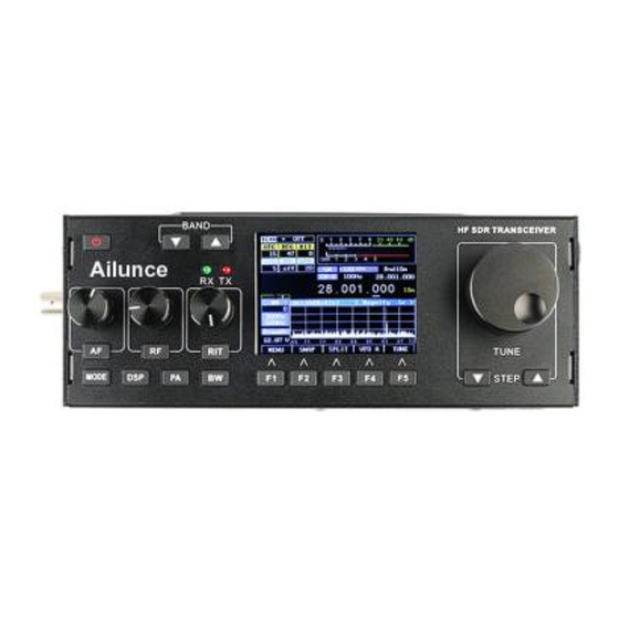
STEP-, STEP+ – This sets the tuning step size in steps that include 1 Hz, 10 Hz, 100 Hz, 1 kHz, 10 kHz, and 100 kHz. The Figure 1:Front panel controls of the HS1 transceiver function of these buttons may be swapped via a menu setting. - Page 4 “LSB/USB Auto Select” is enabled, in order to change to AM you must select a mode other than LSB (or USB) – such as CW – and then press-and-hold button Mode - AM will then be selected. Figure 2: Main display of the HS1 transceiver...
-
Page 5: Main Display
Ailunce HS1 User’s Manual Main Display: BW – This button is used to select the audio pass band filter of the receiver. Pressing-and-holding this button will force the selection of bandwidth that are otherwise disabled. The filter-selection function of this button is disabled when the FM... - Page 6 Ailunce HS1 User’s Manual thermally-bonded to the temperature sensor, U10, with a • RIT+Tuning Display: Above and to the right of the piece copper aluminium apply main frequency display is a smaller display that is offset compensation to it to keep on frequency. When it is active...
-
Page 7: Spectrum Display
Ailunce HS1 User’s Manual • FIL: Below this is the current filter bandwidth setting, indicates the output power from the transmitter. selectable by using button BW. In Figures 2 and 3the bandwidth is shown being set to 2.3 kHz. • Multi-function display: Below the S-Meter and Power Output meter is a multi-function meter that, using button •... -
Page 8: Waterfall Display
Ailunce HS1 User’s Manual Options available to both the Spectrum Scope and Waterfall Waterfall display: Display: Figure 4 shows an alternate method of displaying signals near the • An adjustable “smoothing” filter (menu item “Scope/Wfall currently-tuned receiver signal is the Waterfall Display. In this mode, the frequency is displayed along the “X”... - Page 9 Ailunce HS1 User’s Manual • Accessory (J3). This is used for interfacing with an • Microphone/PTT (J3). This connector has both a external device and may be used for keying the transmitter microphone connector with bias voltage (if R68 is installed) and/or determining when the transmitter is keyed.
- Page 10 • When in TUNE mode audio being input to the Microphone and LINE inputs will be ignored. After powering up, the HS1 transceiver will revert to receive mode on the last frequency, in the mode and using the audio • When TUNE is activated in SSB mode, the frequency offset from bandpass filter that was in use when it was last powered down the display frequency and the sidetone frequency (e.g.
- Page 11 Ailunce HS1 User’s Manual transmit: The transmit mode is always that of the “active” (receive) VFO. • Dial in your receive frequency of 14.155 – the transmit frequency The SPLIT mode will be discussed in more detail below. of the DX station – and also set USB mode and your desired filter If one PRESSES AND HOLDS this button (F4) the currently active VFO's bandwidth.
- Page 12 Ailunce HS1 User’s Manual “Soft” buttons in normal operation: • EXIT (button F1) – This exits the menu system, returning to the In “normal” operation the spectrum display will be visible on the main display. Pressing-andholding this button will save all settings to screen and the five “Function”...
- Page 13 Ailunce HS1 User’s Manual level of the sidetone that is heard during keying while in CW mode • RIT - “Receive Incremental Tuning”. This offsets the receiver, in 20 and while in TUNE mode using encoder ENC1. Button M1 may be...
- Page 14 NR Strength” - but be very careful with this as it easy to go overboard with the HS1 to slow down significantly! What this means is that the this setting. If it is set too high, the artifacts caused by the noise reduction response to button-presses and the updates of the (e.g.
- Page 15 Note: transceiver's response – and also why the noise blanker is disabled in If you are unfamiliar with the HS1, please refer to the section AM mode and when set to a wide bandwidth mode – either of which of the manual: “Before you get on the air - Initial set-up of take more processor power in their own right! the HS1 transceiver”...
- Page 16 UI board, below • NR+NOT = Both Noise reduction and Automatic and to the right of the FREQ ENC control. The HS1 is typically used notch filter. with an electret-type microphone element and power for the microphone element is supplied by the radio.
- Page 17 When the • In a quiet room with an antenna or dummy load connected to the HS1, set translation is active, instead of the receiver operating at and around "DC", the METER mode to ALC and key the microphone/transmitter without the signals are mathematically shifted from 6 kHz (above or below –...
- Page 18 LCD power supply modifications (for UI board 0.3) but they should go a The HS1 may be connected to a computer, tablet or smart phone via audio long way toward reducing the artifacts that can still occur even after making...
- Page 19 • It should be noted the the LINE OUT jack will contain the transmit Connect the Line-Input jack (J2) of the HS1 to the audio output of the device audio. This is an artifact of the hardware configuration.
- Page 20 DISABLE function. If this mode is on, the TUNE indicator will turn were released during a dash and vice-versa. gray and all transmit capabilities of the HS1 will be disabled. This is the • STR_K – Straight Key. This would be used for a straight key, a same as the parameter “Transmit Disable”...
- Page 21 • Press the paddle/key to cause the HS1 to transmit: Use ENC1 to are communicating. The loudness of this tone may be adjusted using the adjust the volume of the sidetone.
- Page 22 Ailunce HS1 User’s Manual • ENC2 – Selects the individual menu item. There are two separate menus within the menu configuration system: • ENC3 – Adjusts the selected menu item • The MAIN menu. These are the more commonly-adjusted items with •...
- Page 23 Ailunce HS1 User’s Manual noise reduction, with 0 being “weak” and higher numbers • Wide Filter Select - This selects the “wide” filter – that is, the next correlating to “stronger” DSP noise reduction effects. The relative bandwidth above the 3.6kHz bandwidth with four bandwidth being effects of this parameter are affected by the “advanced”...
- Page 24 Ailunce HS1 User’s Manual you must select a mode other than LSB (or USB) – such as CW – and even this will result in a bit of added distortion as the filter about as then press-and-hold button G1: AM will then be selected.
- Page 25 Ailunce HS1 User’s Manual AGC and other receiver-related items: • RX NB Setting - This is the same as the “NB” setting on the main screen. This adjusts the “strength” of the noise blanker, with “0” being • AGC Mode - The selections are SLOW, MEDium, FAST, off.
- Page 26 Ailunce HS1 User’s Manual For more information, refer to the section about Frequency result in a small amount of compression for low values or “heavy” Translation near the end of this document. compression for high values. When set to “SV” (which would be setting “13”) the “ALC Release Time”...
- Page 27 Ailunce HS1 User’s Manual Side/Off Freq”). One must do some mental math to calculate the • When adjusting the sidetone, always take care to be sure that actual transmit frequency. the center frequency 300 Hz and/or 500 Hz filter that you use •...
- Page 28 Ailunce HS1 User’s Manual frequency and it is the frequency of the received signal if it is second or so and the temperature is displayed, but the frequency is not tuned to match the pitch of the sidetone. corrected based temperature.
- Page 29 Ailunce HS1 User’s Manual • Spec. Grid Colour - This sets the color of the background grid of the It is recommend that you find the optimal setting for the spectrum spectrum scope. scope and then leave it there rather than adjust it for the waterfall •...
-
Page 30: Configuration Menu
Ailunce HS1 User’s Manual sluggish. Such is indicated by color change of this adjustable ◦ INVGrey – This is the “inverse” of the “Grey” palette in that parameter from Yellow to Red as this effect will (likely) increase – weak signals are light and strong signals are dark. - Page 31 Ailunce HS1 User’s Manual have the STEP buttons swapped as well. the Spectrum Scope or Waterfall display that graphically depicts both • Transmit Disable - When ON, all transmit functions are disabled. the bandwidth and frequency span of the currently selected filter and This may also be toggled by pressing-and-holding the TUNE button.
- Page 32 • Please read the procedure for calibration of the RX IQ gain and transceiver in Hz, referenced to 14.000 MHz. Please refer to the phase balance for more detailed information. This procedure may be section “Calibrating the HS1’s Operating Frequency” at the end of found elsewhere in this document. this document.
- Page 33 Ailunce HS1 User’s Manual transmit, it is necessary that the bias first be set in SSB mode, NOT in • USB/CW RX IQ Bal. - This adjusts the IQ Gain balance in USB/CW RX mode. TUNE mode, by keying the PTT with no audio and then noting the •...
- Page 34 Ailunce HS1 User’s Manual • 40m Coupling Adj. - This adjust the calibration factor for the frequency step sizes will be available for tuning the main frequency forward and reverse power sensors when operating on 40 and 60 dial. meters. If a known-accurate wattmeter is available, use this adjustment •...
- Page 35 (e.g. 15 meters and above.) Please follow the discussions • If you see the settings for the “FULL” power adjust defaulting on the Yahoo Group and check the “HS1 board modifications” to ZERO, first POWER document for updates on this topic.
- Page 36 • DSP NR FFT NumTaps – This is the number of taps in the FIR • Note that “officially” the HS1 transceiver is just a 5 watt radio, but (filter) comprising the DSP noise reduction filter. A smaller number of...
- Page 37 Ailunce HS1 User’s Manual prior to the AGC, the “quieting” caused by the noise reduction can “simulate” one by delaying the original signal to “de-correlate” will be compensated by the AGC and the perceived “quieting” it. If we delay it too little, it will resemble the original signal too effect caused by the noise reduction will be reduced.
- Page 38 Ailunce HS1 User’s Manual ◦ Note that while fidelity is improved when this filter is turned The following windowing functions are available: off, “talk power” is reduced as more transmit energy is devoted • Rectangular: This is the same as no window function and the parts of the voice that do not carry information.
- Page 39 Ailunce HS1 User’s Manual The function with the best sidelobe rejection is the Hann, but even Notes about adjustment of DSP-related configuration values: though it is wider than the Hamming or Blackman this can also cause some weaker signals to become more difficult to see owing to its...
- Page 40 Ailunce HS1 User’s Manual With very high “strength” settings and the slow adaptation rate, one may The notch filter operates within the signal path prior to the AGC and the perceive that the filter may be “stuck”, but turning the DSP filter off and DSP NR operation, so a strong “tune up”...
- Page 41 “hs1_board_modifications_xxxx” file that may be best-fit the dynamic range selected by the userselected found in the FILES section of the YAHOO HS1 Yahoo group. dB/division. A graticule along the bottom of the display indicates the approximate frequency of the signal being Because this is a software-defined radio and due to ongoing displayed over a width of +/- 24 kHz.
- Page 42 ▪ 15 kHz BW filter: -99dBm dBm (2.50uV) with 1 kHz tone computer or tablet/smart phone) and operate “Sound Card” modes at +/- 3 kHz with the HS1 such as SSTV, PSK31, WSPR and other analog/digital • CW mode receive/transmit and frequency display details: Nine modes.
- Page 43 ◦ 16.0 volts maximum Prior to the addition of the ALC the POWER adjustment on the HS1 was ◦ To 11.0 volts minimum for full transmit power somewhat irrelevant when in a voice mode as it only added effective ◦...
- Page 44 Ailunce HS1 User’s Manual With the ALC the PEP power from the transmitter should not exceed • Adjust this setting for an upwards indication of the ALC indicator. the carrier level observed in TUNE mode, no matter the audio drive See below for a discussion of this setting.
- Page 45 Ailunce HS1 User’s Manual SSB operation with minimal speech compression: is NOT filtered in any way and signals outside the frequency range that would be transmitted (e.g. <200 Hz, >3500 Hz) will register. • Set the Microphone/Line gain as described in the previous section (e.g.
- Page 46 • If the HS1 is being operated from lower than normal supply voltage • The power supply voltage is low. If you are operating the radio on a the RF amplifier may be unable to output a normal amount of power.
- Page 47 Ailunce HS1 User’s Manual will need to operate at a lower power than this “maximum” output! Amplitude Modulation (AM) mode reception and transmission: • If the PA Bias was never set properly your RF amplier, nonlinear operation may result. In order to set the PA Bias do the following steps: As of firmware version 0.0.217 there is the ability to enable “Frequency...
- Page 48 Ailunce HS1 User’s Manual Other (“non-wide”) bandwidths are available: passband also be intercepted. The selectable audio filter was applied after the demodulation, but if there was an extraneous signal within the +/-10kHz • 3.6 kHz: Pre-detection bandwidth: +/-3.6 kHz (7.2 kHz total);...
- Page 49 1000 Hz “tweet” tone. • The UNMODULATED resting carrier will be 25% of that of the A recommended modification for HS1 Board version 0.4 (and possibly peak power! This means that if you are used to getting 5 watts peak on earlier) if you are interested in AM reception: SSB, you will get only 1.25 watts when no audio is present: Sorry...
- Page 50 – useful for checking for a simplex path. The “FM” produced by the HS1 is compatible with PM, which is to say that for modulation, a 6dB/octave preemphasis is applied and a 6dB/octave de-emphasis is done on receive audio: This is the worldwide standard...
- Page 51 Ailunce HS1 User’s Manual for narrowband frequency modulation on amateur and commercial • 7.2 kHz – This is suitable only for “Narrow” operation and even this frequencies. will result in a bit of added distortion as the filter about as narrow as it may be to pass audio.
- Page 52 Ailunce HS1 User’s Manual Tone Burst generation: Additional comments: Although it is getting rarer, some repeaters may still require “tone burst” • The audio (speech) processor is active on FM, but owing to the nature of and this is enabled by setting the menu item “FM Tone Burst” to something FM communications (e.g.
- Page 53 ◦ Connect a known-good dummy load to the HS1. ◦ Connected a known-good wattmeter and dummy load. ◦ Set the HS1 to 10 meters and the mode to LSB or USB. ◦ Set the transmitter to CW mode. ◦ Go to the Calibration menu item “PA Bias”.
- Page 54 ◦ Connect a dummy load to the transmitter ◦ Repeat the above steps for each band. ◦ Once the “5W PWR Adjust” settings are obtained, set the HS1's ◦ Make certain that the MICROPHONE input is selected and turn the microphone gain setting to minimum.
- Page 55 Ailunce HS1 User’s Manual ▪ If you still get radically different forward/reverse readings, check transmitter and then press-and-hold the F1 button to save the setting the voltages on pins 9 and 10 of the 30 pin connector: They should to memory.
- Page 56 Additional settings: button to save the settings to EEPROM. The following settings should be known to the HS1 operator. Please refer to • Frequency Calibration: This step requires several things: the previous sections containing the menu items for more details on their use.
- Page 57 – a signal generator is preferred. frequency. (The dial frequency would be 7201 kHz, using the 4. Tune the HS1 dial frequency 1 kHz above the carrier frequency to example above.) obtain a strong 1kHz audio note. Example: If your signal generator is ◦...
- Page 58 NOTE for CW operators who use "lower" CW sidetone frequencies: used. This procedure is included for completeness. If you use the HS1 primarily for CW, use rather low frequency CW notes and sidetone frequencies (400-550 Hz) and notice "leakage" from the 1) Set the HS1 to LSB mode...
- Page 59 2-10 dB. If 6. Press the TUNE button. The audio on the HS1 audio should mute and there is no easily discernible difference using your measuring method you should see, on the waterfall display, a signal 750 Hz below the HS1 set this value to zero.
- Page 60 5. Tune both the HS1 and the computer-connected receiver to the same frequency. 6. Press TUNE mode. You will hear a 750 Hz tone from the HS1 and see it on the waterfall display, see a signal 750 Hz below the HS1 dial display frequency.
- Page 61 13. Switch the computer-connected receiver in LSB mode, but this kHz sizes are actually useful considering the +/-9999Hz adjustment range! time null out the 750 Hz tone BELOW the HS1 dial frequency, having done the math to figure out where the frequency components will land! If you use the TCXO feature of the HS1: •...
- Page 62 If you do NOT use the TCXO feature of the HS1: possible to detect the local oscillator radiating from the HS1 and For most users there is no reason NOT to use the TCXO feature of the HS1 observe the oscillator frequency directly. If you do this, temporarily set as it will greatly improve frequency stability with changing temperature.
- Page 63 Frequency translation mode is necessary for AM TX and for FM "HS1 Board Modifications" file, particularly the U3a and MCU and LCD RX/TX operation. power supply modifications (for UI board 0.3) but they should go a long...
- Page 64 The reason for this is that there is only ONE D/A converter on the HS1 and with the frequency translation occurring, it is possible only to patch through the signal being fed to the modulator - which is no longer at "baseband."...
-
Page 65: Menu Mode
Ailunce HS1 User’s Manual HS1 Key function matrix Button(s) Brief press Press-and-hold >1 second Power Change display brightness Power on and power off/save settings to memory Select AFG and CMP or STG Select RFG and DSP or NB Switch between DSP and NB... - Page 66 Ailunce HS1 User’s Manual Operational notes, quirks, and known bugs: group. Please make sure that the “Frequency Translate” function is active as this will also reduce this noise. • CW operation will be impaired while in the menu system! It is •...
- Page 67 LCD when the display is dimmed. This document may be found in the FILES section of the The HS1 transceiver consists of two boards: The UI (User Interface) board YAHOO group in the KA7OEI folder. Changes have been incorporated in that contains the MCU (computer) and display, along with the audio version 0.4 of the UI board to reduce this along with using the “Frequency...
- Page 68 RF Synthesizer: An Si570 clock generator (U8) is used as the RF signal source for the HS1 Transformers T2 and T3 form what is known as a “Tandem Coupler”, being transceiver. This device, capable of part-per-billion tuning resolution, directionally sensitive to the flow of RF current through the primary of T2.
- Page 69 Ailunce HS1 User’s Manual energized only briefly, holding their state indefinitely until change and thus While this can cause a small amount of signal reduction owing to the losses saving power. By setting the appropriate combination of relays and contacts of T7 and the shunting effects of the RF power transistors Q5 and Q6, this the appropriate low-pass filter may placed inline.
- Page 70 Ailunce HS1 User’s Manual RX Detector: signals for both I and Q. The two outputs from each channel are further-boosted to a low-impedance source using LM386 audio amplifiers, The “RX_QSD_IN” signal from the bandpass filter is applied to RF U20-U23.
- Page 71 3.3 volt rail in the original operates in a stable mode and does not oscillate, causing distorted design which resulted in circulating currents in the ground of the HS1 and transmit signals. A minimum of a 22 uF Tantalum (or 100 uF...
- Page 72 For older boards that use the HY28A, the interface to the LCD is based on one A/D converter on the HS1. In receive mode,U3 always routes the audio the SPI (serial) interface which is very much slower, but a separate set of from U16 to the “LLINEIN”...
- Page 73 Ailunce HS1 User’s Manual After being processed by the MCU, the receive audio is sent back to U1 via volumes and with strong signals the audio going into U17 exceeded the 5 the SPI interface and it is output on the output pins. On this particular codec, volt supply voltage of that device causing it to falsely turn on, creating there are two sets of outputs: “LHPOUT”...
- Page 74 Ailunce HS1 User’s Manual RF ENERGY EXPOSURE AND PRODUCT SAFETY GUIDE FOR PORTABLE TWO-WAY RADIOS Before using this radio, read this guide which contains important operating instructions for safe usage and RF energy awareness and control for compliance with applicable standards and regulations.
- Page 75 Ailunce HS1 User’s Manual This device complies with part 15 of the FCC Rules. Operation is subject to the following two conditions: (Other devices are applicable) (1) This device may not cause harmful interference, and (2) this device must accept any interference received, including interference that may cause undesired operation.
- Page 76 Ailunce HS1 User’s Manual externally-mounted antenna to satisfy the RF exposure requirements. •Occupational/Controlled Radio, this radio is designed for and classified as “Occupational/Controlled Use Only”, meaning it must be used only during the course of employment by individuals aware of the hazards, and the ways to minimize such hazards;...
- Page 77 Ailunce HS1 User’s Manual •Turn off your radio before removing (installing) a battery or accessory or when charging battery. •Turn off your radio when you are in a potentially hazardous environments: Near electrical blasting caps, in a blasting area, in explosive atmospheres (inflammable gas, dust particles, metallic powders, grain powders, etc.).
- Page 78 Ailunce HS1 User’s Manual Forbid •Do not use charger outdoors or in moist environments, use only in dry locations/conditions. •Do not disassemble the charger, that may result in risk of electrical shock or fire. •Do not operate the charger if it has been broken or damaged in any way.
Need help?
Do you have a question about the HS1 and is the answer not in the manual?
Questions and answers