Table of Contents
Advertisement
Intan CLAMP System
Features
♦
Complete, miniaturized patch clamp amplifier system
with small digital headstages using revolutionary
CLAMP microchips from Intan Technologies
♦
Voltage clamp operation with low current noise floor:
< 3 pA
over 5 kHz bandwidth with highest sensitivity
rms
♦
Current clamp operation with low voltage noise floor:
< 20 µV
over 10 kHz bandwidth
rms
♦
Fast transient capacitance compensation: 0-20 pF
range; bridge balance in current clamp mode
♦
Automated measurement of pipette / seal resistance
and cell membrane parameters
♦
Clamp operation controlled by software and/or external
analog voltage command signals
♦
Small headstage size: 6.1 cm × 2.8 cm × 2.0 cm (not
including pipette holder)
♦
Standard threaded Teflon pipette electrode connector
♦
Standard dovetail for mounting to micromanipulator
♦
All-digital interface cable is immune to noise pickup
♦
Standard USB interface to host computer
♦
Free, open-source, multi-platform GUI software
Voltage/Current Clamp
www.intantech.com ● info@intantech.com
Intan CLAMP System
User Guide
16 September 2016; updated 14 May 2019
Description
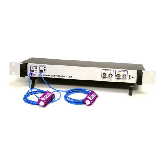
The Intan Technologies CLAMP patch clamp amplifier
system allows users to perform signal channel or multi-
channel patch clamp electrophysiology or electrochemistry
experiments using the revolutionary new Intan CLAMP
voltage/current clamp chips.
The Intan CLAMP system incorporates all analog circuitry
and many digital control blocks in close proximity to the
electrode, resulting in a miniaturized "headstage" that is
actually a complete patch clamp amplifier. Thanks to the
integration of nearly all patch clamp circuit elements onto a
single silicon chip, the Intan-powered patch clamp amplifier
is smaller than traditional analog headstages that perform
only a small fraction of the total amplification task.
The Intan digital CLAMP headstages are interfaced to the
Intan CLAMP Controller which coordinates the operation of
the voltage/current clamps as well as sampling auxiliary
digital and analog signals in synchrony with the measured
electrophysiological signals. The interface cables are purely
digital with independently isolated grounds, making them
immune to noise pickup or signal degradation.
The Intan CLAMP Controller connects to a host PC via a
standard USB bus, and operates using free, open-source
software.
1
Advertisement
Table of Contents

Summary of Contents for Intan Technologies CLAMP
- Page 1 ♦ All-digital interface cable is immune to noise pickup The Intan CLAMP Controller connects to a host PC via a ♦ Standard USB interface to host computer standard USB bus, and operates using free, open-source ♦...
-
Page 2: System Architecture And Theory Of Operation
Intan-powered digital headstages (see diagram above). A small circuit board containing an Intan CLAMP chip and a small number of support components form a complete patch clamp amplifier with a purely digital interface. The Intan digital “headstage” is actually a complete, miniaturized patch clamp amplifier. Thanks to the integration of nearly all patch clamp circuit elements onto a single silicon chip (see “actual size”... -
Page 3: Intan Clamp Headstages
Intan CLAMP System Intan CLAMP Headstages An Intan CLAMP headstage is shown above with a pipette holder and glass pipette attached (not included). Intan headstages mate with thread-mounted pipette holders that are compatible with Axon amplifiers. Pipette holders sold by Molecular Devices (the 1-HL-U), Warner Instruments (the Q series), and other companies may be used with Intan headstages. -
Page 4: Controller Hardware
Rear Panel The rear panel of the Intan CLAMP Controller provides auxiliary output lines as well as other ports and switches. From left to right: Analog outputs: Two BNC sockets are provided for monitoring measured signals or clamp signals from CLAMP •... - Page 5 Mounting The Intan CLAMP controller can be rack mounted on a standard 19” instrument rack using provided hardware, or it can be used on a bench top by folding out the feet on the bottom of the case: www.intantech.com ● info@intantech.com...
-
Page 6: Intan I/O Expander
Intan CLAMP System Intan I/O Expander Intan Technologies offers an optional I/O Expander (sold separately) that provides an additional six analog inputs and outputs and an additional 14 digital inputs and outputs. This unit is shown below: Front Panel The front panel of the Intan I/O Expander provides auxiliary digital and analog inputs, and analog outputs. From left to right: Analog outputs: Two analog outputs for monitoring measured signals or clamp signals from CLAMP headstages. -
Page 7: Software Installation
To run the software, double click the executable. Plug in at least one CLAMP headstage to one of the ports on the front panel and start the software. The software takes a few seconds to calibrate the attached headstages and then opens two windows: a Control Window (see right) and a Data Display Window (see below). - Page 8 Plot total Vclamp: Checking this box adds a second plot on Voltage Clamp Controls the Clamp Voltage graph in the lower half of the Data Display Clicking on the Voltage Clamp tab displays the following Window.
- Page 9 External Command Tab: Controls in this tab allow the user the measured voltage or current signal to any of the to control the voltage clamp or current clamp in real time via ANALOG OUT ports for monitoring on an oscilloscope or external command signals from any of the ANALOG IN speaker.
-
Page 10: Data Display Window
Intan CLAMP Controllers goes high made. As shown in the plot below, a voltage clamp step is when the clamp waveforms departs from the holding level. -
Page 11: Bridge Balance
V elec cell However, the clamp current flows through a series After breaking into a cell, the voltage clamp is typically set to resistance R comprised of the pipette resistance R and the a value near the cell’s expected resting potential (e.g., -70 access resistance R . -
Page 12: Arbitrary Waveform Specification
Clamp Range control in the Current Clamp tab. The step This wide voltage clamp range permits the Intan CLAMP size can be 5 pA, 50 pA, 0.5 nA, or 1 nA. The current clamp Controller to be used in fast-scan cyclic voltammetry (FSCV) level can range between -127 and +127 steps. - Page 13 Intan CLAMP System recognize data saved with the 2x mode enabled and automatically adjusts voltage clamp waveforms to reflect the true voltages. www.intantech.com ● info@intantech.com...
-
Page 14: Importing Recorded Data Into Matlab
Running this m-file brings up a file selector dialog with which the user locates and selects the desired .clp data file. The m-file then loads and parses the data file and returns a data structure containing the clamp and measured waveforms, time vectors, and settings. - Page 15 DigitalOut (The Intan CLAMP Controller has two DIGITAL IN lines and two DIGITAL OUT lines; the Intan I/O Expander can be added to gain access to all 16 signals.) For example, if DIGITAL IN 1 and DIGITAL IN 7 are both high and all other digital inputs are low, then...
-
Page 16: Related Clamp Documentation
Intan Technologies’ products are not authorized for use as critical components in life support devices or systems. A critical component is any component of a life support device or system whose failure to perform can be reasonably expected to cause the failure of the life support device or system, or to affect its safety or effectiveness.
Need help?
Do you have a question about the CLAMP and is the answer not in the manual?
Questions and answers