Advertisement
Table of Contents
Advertisement
Table of Contents

Related Manuals for Xilica Audio Design XP 4080


Summary of Contents for Xilica Audio Design XP 4080
- Page 1 XP SERIES User Manual...
- Page 2 Important Safety Information 1. READ THESE INSTRUCTIONS All the safety and operating instructions should be read before the product is operated. 2. KEEP THESE INSTRUCTIONS The safety and operating instructions should be retained for future reference. 3. HEED ALL WARNINGS All warnings on the product and in the operating instructions should be adhered to.
-
Page 3: Table Of Contents
Table of Contents Labels and Descriptions Technical Specifications Install XConsole Launch XConsole Connection Troubleshoot 10-11 12-13 Firmware Upgrade Export/Import Files, Going Online Front Panel 16-22 Channel Menu System Menu 23-28 Quick Reference Contact and Support... -
Page 4: Labels And Descriptions
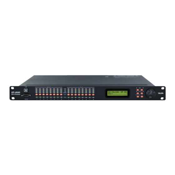
Front Panel OUTPUTS INPUTS Ethernet Control FUSE: T2.5A-250V MAINS: 90-240 VAC 50-60Hz, 20VA INPUTS OUTPUTS INPUTS OUTPUTS LIMIT MENU -3dB -8dB XP 8080 -12dB CURSOR SIGNAL DSP Processor MUTE ENTER/SYS EXIT MENU RS232 A standard Type B USB connector. The device USB driver must be installed. - Page 5 Ethernet Control OUTPUTS INPUTS MAINS: 90-240 VAC 50-60Hz, 20VA FUSE: T2.5A-250V INPUTS OUTPUTS LIMIT MENU -3dB -8dB XP 4080 -12dB CURSOR SIGNAL DSP Processor Power switch MUTE Power ON/OFF the processor using this switch. ENTER/SYS EXIT MENU RS232 Power supply Insert the plug connector into the socket.
- Page 6 Rear Panel (XP 8080) OUTPUTS INPUTS Ethernet Control MAINS: 90-240 VAC 50-60Hz, 20VA FUSE: T2.5A-250V INPUTS OUTPUTS LIMIT MENU -3dB -8dB XP 8080 -12dB CURSOR SIGNAL DSP Processor MUTE Power switch Power ON/OFF the processor using this switch. ENTER/SYS EXIT MENU RS232 Power supply...
-
Page 7: Technical Specifications
Technical Specifications Input impedance >10k Ohms Output impedance 50 Ohms Maximum level +20dBu Mic/Line Mic (+40dB Fixed gain)/Line (0dB) Type Electronically balanced Frequency response +/-0.1dB (20 to 30kHz) Dynamic range 115dB typ (unweighted) CMRR >60dB @ 1kHz Crosstalk <-80dB @1kHz Distortion 0.002% (1kHz @ +4dBu) Processor... -
Page 8: Install Xconsole
Install XConsole The XConsole software provides optimum configuration of XD and XP Series processors. Windows Installation System Requirements PC computer with a processor 1GHz or higher Windows 7 or higher 500MB of available space 1GB graphics card 4GB RAM Download the latest version of XConsole from the Xilica website (www.xilica.com). Open the downloaded .zip file. -
Page 9: Launch Xconsole
Launch XConsole Locate the XConsole application on your Desktop or Applications folder. Double click the application to launch the software. Devices will display as a list on the left. Double click a device to open the device parameters. -
Page 10: Connection Troubleshoot
Connection Troubleshoot Please make sure that you are using the latest version of XConsole (v9.04). For serial port/USB, Open up the XConsole software. Under the Setup tab at the top, select Port Connection. A window will appear. Click on Device Manager. Under Ports (COM &... - Page 11 Cat5 Ethernet connection X Series IP Address can be configured on the front panel of the device or in the software. On the front panel of the device, click the Enter button to enter the System menu. Use the Menu arrows to navigate to the Ethernet menu. The device IP Address can be viewed.
-
Page 12: Firmware Upgrade
Firmware Upgrade Please note that using an older version of software with a newer firmware or newer software with an older firmware will work but some of the features may not be available and bugs could exist. We recommend upgrading the software and firmware to the latest versions. Before you begin, check your software and firmware versions. - Page 13 The green status bar in the device window will display the Firmware Upgrade process. This may take several minutes. DO NOT POWER OFF THE DEVICE. Powering off the device during a Firm- ware Upgrade can result in a complete corruption of the processor. Once the Firmware file has completed, the device will need to be manually switched Off and On again.
-
Page 14: Export/Import Files, Going Online
Export/Import Files and Going Online To load device settings from the computer to the device, or save settings from the device to the computer, Open the device parameters. Click Preset located at the bottom left of the window. There are three options: Transfer Presets from PC to Device. -
Page 15: Front Panel
Navigate Front Panel Upon powering up the unit, the unit will start up and display the device model and firmware version. ***** XILICA -4080 ***** -4080 v9.00B Once initialized, the device screen will display the current program number and program name assigned to the unit. - Page 16 Input microphone gain (Only available for XP 2040-M, XP 4080-M and XP 8080-M models) I1: _______ LEVEL: 0dB LEVEL The level (or gain) ranges from 0dB to +45dB in 3dB steps. This level will only have an affect on the input channel when Mic input is selected from the system menu.
- Page 17 Input/Output Equalizers I1: _______ I1: _______ EQ#: 1 BW:0.33 Q=4.36 I1: _______ I1: _______ BYPASS: Off DEG: 15.5 deg I1: _______ I1: _______ LEVEL: 0.00dB TYPE: PEQ I1: _______ FREQ: 1000Hz The level (or gain) ranges from -40dB to +15dB in 0.25dB steps. BYPASS The polarity (or phase) can be normal (+) or inverted (-) TYPE...
- Page 18 Input Graphic Equalizer I1: _______ GEQ1 GEQ#: 1 f=20 I1: _______ GEQ1 LEVEL: 0.00dB I1: _______ GEQ1 BYPASS: Off GEQ# The graphic equalizer has 31 bands of equalization from 20Hz to 20kHz. This control selects one of the 31 available bands. The frequency corresponding to each band is also shown.
- Page 19 Input/Output Crossover 01: _______ XOver 01: _______ XOver TYPH: Off TYPL: Off 01: _______ XOver 01: _______ XOver FRQL: 1000Hz FRQH: 1000Hz 01: _______ XOver 01: _______ XOver SLPL: 24dB SLPH: 24dB TYPL The three available filter types for the low frequency crossover point (high pass) are: Butterworth, Linkwitz-Riley or Bessel.
- Page 20 Input Compressor 01: _______ Comp 01: _______ Comp THRESH: +20.0dB RELEASE: 8XAtck 01: _______ Comp 01: _______ Comp ATTACK: 10ms RATIO: 1:1 THRESH The compressor threshold ranges from -20dBu to +20dBu in 0.5dB steps. ATTACK The compressor attack time ranges from 0.3ms to 1ms in 0.1ms steps, then ranges from 1ms to 100ms in 1ms steps.
- Page 21 Input/Output Channel Name I1: _______ Name NAME:________ NAME A six character name can be assigned to each channel. Output Limiter 01: _______ Limit 01: _______ Limit THRESH: +20.0dB RELEASE: 8XAtck 01: _______ Limit ATTACK: 10ms THRESH A limiter threshold ranges from -20dBu to +20dBu in 0.5dB steps. ATTACK The limiter attack time ranges from 0.3ms to 1ms in 0.1ms steps, then ranges from 1ms to 100ms in 1ms steps.
- Page 22 Output Source I1: _______ Source IN1: Off IN1-8 This sets the input channel source for the current output channel. It can be used to mix the input source (in dB) or disable it (Off). If more than one input sources are enabled, they will be added together as the source for the current output channel.
-
Page 23: System Menu
System Menu The System menu allows the user to control and change parameters that are related to the system behaviour and general operation. To access the system menu, Make sure you are first in the main menu. (Press the Exit button to return to the main menu any time). - Page 24 Preset Store SYSTEM Store SYSTEM Store NAM: ____________ The has a built-in non-volatile memory that can store up to 30 different program (or preset) set- ups. A program can be stored using this menu. The old program with the same program number will be replaced.
- Page 25 Phantom Power SYSTEM Phantm IN1: On The optional microphone pre-amp also comes with Phantom power, which can also be enabled or disabled from this menu. IN1-8 A 48V DC voltage can be supplied to external microphone when the Phantom power is enabled. Phantom power cannot be enabled individually for each input channel.
- Page 26 General Settings SYSTEM Generl FREQ MODE: All SYSTEM Generl DELAY UNIT: ms Copy channels from the source to the target. When the source and targets are both inputs and outputs, all audio parameters will be copied. When the Source or the Target is an input while the other is an output, only the Level, Polarity, Delay, EQ, Crossover, and Channel name are copied.
- Page 27 Communication Settings SYSTEM Comm SYSTEM Comm NETWORK ID: 0 DEVICE ID: 1 SYSTEM Comm BAUD RATE: 115200 NOTE: The user must power cycle the unit for this setting to take effect. DEVICE ID This control assigns a device ID from 1 to 16 to the unit. BAUD RATE Sets the baud rate of the serial communication.
- Page 28 Factory Settings SYSTEM Reset CURRENT: Yes CURRENT This resets all the current parameters back to factory default settings only, while stored presets and system settings stay untouched. ISO Settings SYSTEM THRESHOLD: 102 SYSTEM BYPASS: On This internal system optimizer reduces ground floor noise if no signal is present. If unwanted noise gate effects are audible at low sound levels, it can be switched to bypass mode INFO SYSTEM...
-
Page 29: Quick Reference
Quick Reference Menu Field Parameters Steps Units <<Menu>> <<Cursor>> Mic level LEVEL Level Signal LEVEL 0.25 Polarity Signal +/ - Delay Signal DELAY 62400 10us steps EQ number EQ bypass BYPASS Off/On EQ type TYPE PEQ / Lo-Shf / Hi-Shf / AP-1 / AP-2 EQ level LEVEL 0.25... -
Page 30: Contact And Support
Customer Support If you’d like to contact us regarding product support or technical designs, email support@xilica.com and we’ll connect you with a solutions engineer Alternatively, if you’d like to speak to someone, you can call the following numbers for immediate assistance: International: +1 905 770-0055 US Toll Free:...
Need help?
Do you have a question about the XP 4080 and is the answer not in the manual?
Questions and answers