Table of Contents
Advertisement
MODEVA Technical Reference Manual
This document contains information that is the proprietary and confidential property of INNCOM
International Inc. By acceptance hereof, each recipient agrees to use the information contained
herein only for the purpose anticipated by INNCOM, and not to disclose to others, copy or reproduce,
any part hereof without the written consent of INNCOM. The recipient agrees to return this document
to INNCOM immediately upon request.
1
MODEVA Product Overview ........................................................................................ 2
2
MODEVA System Block Diagram ................................................................................. 2
3
Touch User Interface ................................................................................................ 3
4
MODEVA Logic Board ................................................................................................ 4
4.1
RF capability ........................................................................................................... 5
4.2
S5-bus ................................................................................................................... 5
4.3
IR Tx and Rx ........................................................................................................... 5
5
Load Assembly ........................................................................................................ 5
5.1
Categories of Load Assembly Load Switching ................................................................ 5
5.2
Load Assembly Dimming ........................................................................................... 6
5.3
Air-Gap Switch ........................................................................................................ 7
5.4
Overload Protection .................................................................................................. 7
5.5
Load Assembly Parallel Power Supplies ........................................................................ 8
6
MODEVA System Technical Specification ...................................................................... 8
6.1
MODEVA/Load Assembly Current Consumption Characteristics ...................................... 10
7
Load Specifications ................................................................................................. 10
7.1
Single gang installation ........................................................................................... 10
7.2
Multigang Installation ............................................................................................. 11
8
Multigang Installation Derating Chart ........................................................................ 11
8.1
Actuator Ratings .................................................................................................... 11
9
Standard Wiring ..................................................................................................... 12
10
MODEVA User Interface Assembly Ordering Information .............................................. 13
11
MODEVA Load Assembly Ordering Information ........................................................... 15
11.1 Load Assembly Ordering Information ........................................................................ 15
12
Document Information and Revision History ............................................................... 16
Global Leader in Integrated Room Automation Systems
Disclaimer
Content
Advertisement
Table of Contents

Summary of Contents for Inncom Modeva
-
Page 1: Table Of Contents
International Inc. By acceptance hereof, each recipient agrees to use the information contained herein only for the purpose anticipated by INNCOM, and not to disclose to others, copy or reproduce, any part hereof without the written consent of INNCOM. The recipient agrees to return this document to INNCOM immediately upon request. -
Page 2: Modeva Product Overview
(8mm thick) assembly that rests outside of the wall box cavity. This brings an incredible advantage to MODEVA by allowing it to be decoupled safely from the line power switching and dimming performed by the system’s Load Assembly actuators. -
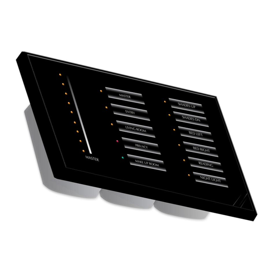
Page 3: Touch User Interface
The sensors sense fields through any dielectric material such as glass or plastic up to 10mm thick. Each sensor can be tuned to a unique sensitivity level. INNCOM plans to provide a single touch user interface layout at the product launch based on a single slider that can be configured in one of the four following ways: ... -
Page 4: Modeva Logic Board
LEDs can be dimmed to a very low level so as not to disrupt the guest’s sleep. When a hand is waved in front of MODEVA, the unit would detect the motion and resume the backlight of the panel to the normal bright levels or could even activate a nightlight. -
Page 5: Rf Capability
MODEVA communicates on the standard INNCOM RF protocol, a proprietary encrypted protocol that runs over the 802.15.4 platform stack. This is a shared protocol that is used by all other RF capable INNCOM products. The protocol’s encryption method provides protection for the P5 frame being sent into the RF spectrum and makes it very difficult to interpret the data and reuse it maliciously. -
Page 6: Load Assembly Dimming
LEDs. The MOSFET dimmer is designed to dim 100–120VAC up to 350W. The MOSFET Actuator also provides a class-2, 12VDC output used to power the MODEVA logic and touch user interface and to provide connection and power for a wired S5-bus IRAS network. -
Page 7: Air-Gap Switch
INNCOM application engineering, operations, and customer service need to be aware of these property conditions to ensure proper operation of the MODEVA light dimmers. A site survey that includes the evaluation of the line voltage at each property must be conducted. -
Page 8: Load Assembly Parallel Power Supplies
A triple ganged MODEVA system can provide up to 550mA to power 12VDC S5-bus devices in the circuit. INNCOM recommends the use of up to seven power supplies in any given network segment. A disadvantage is that a short condition on any one of the actuators will drag all of the actuators into a fold-back state until the short condition is resolved. - Page 9 M O D E V A R e f e r e n c e M a n u a l P a g e 9 o f 1 6 Glass Touch Surface Area Length Width Height American Single Gang 115mm 70mm 2.0mm...
-
Page 10: Modeva/Load Assembly Current Consumption Characteristics
35mA Load Assembly TRIAC Actuator 35mA Load Assembly MOSFET Actuator 35mA For example, a MODEVA assembly that uses the capacitive touch PCBA for a 6 input / output user interface, communicates wirelessly using the 2.4Ghz radio, and ... -
Page 11: Multigang Installation
Electronic Ballast Multigang Installation The MODEVA and Load Assembly comes in single, double and triple gang configurations; the double and triple gang assemblies may be any combination of relay, switches, MOSFET Dimmer or TRIAC Dimmer. The table below provides the derated output based on the configuration. -
Page 12: Standard Wiring
Electronic Ballast Standard Wiring Figure 6 Single Gang Wiring Diagram In Figure 6, the MODEVA and Load Assembly is configured for switching or dimming the level of AC power delivered to a load, such as a Tungsten lighting load. Brown... -
Page 13: Modeva User Interface Assembly Ordering Information
Figure 8 Single Gang Powered Remote Control In the configuration shown in Figure 8, the MODEVA is used as a three-way switch to transmit S5bus or RF signals to auxiliary INNCOM devices to manage in-room communications irrespective of the location of the system devices. - Page 14 User Interface Assembly Ordering Part Number Examples: 03-7060.GHS1.R1.WH = MODEVA user interface assembly switch #1 designed for the Grand Hyatt New York project that includes the CC2430 based radio circuit and a white framing plate. “GHS1” further defines the attributes of the Touch User interface PCB model (ex. GS-765.XXX) in the following: ...
-
Page 15: Modeva Load Assembly Ordering Information
Figure 10 Load Assembly Ordering Part Number Example: 03-7003.L01 = A triple gang MODEVA Load Assembly that includes a low voltage adapter in the left position, a relay actuator in the center position and a TRIAC dimmer in the right position. -
Page 16: Document Information And Revision History
M O D E V A R e f e r e n c e M a n u a l P a g e 1 6 o f 1 6 13 Document Information and Revision History Author Ryan Gardner File \\Niantic\departments\R&D\Working Documents\Reference Manuals\MODEVA\Drafts Date Changes 13-Oct-2009 First Draft 16-Oct-2009...
Need help?
Do you have a question about the Modeva and is the answer not in the manual?
Questions and answers