Table of Contents
Advertisement
Advertisement
Table of Contents
Troubleshooting

Related Manuals for sysmik Scalibur SCA-340

Summary of Contents for sysmik Scalibur SCA-340
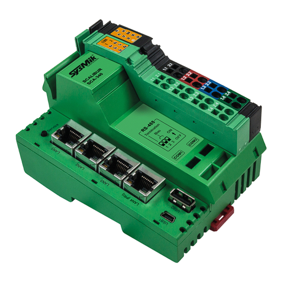
- Page 1 Scalibur – Modular Controllers SCA-340 / SCA-340-L Manual Rev.22...
- Page 2 We are grateful to you for criticism and suggestions. Further information (device description, available software) can be found on our homepage www.sysmik.de. Please ask for latest information.
-
Page 3: Table Of Contents
Current Consumption Calculation for a Scalibur Station (with Terminals) 3.2.2.4 Derating of Terminal and USB Supply 3.2.2.5 Protective Devices of 24 V Main and Segment Supply U and U 3.2.3 RS-485 and LON 3.2.4 Ethernet 3.2.5 USB-OTG for local Access Manual SCA-340 / SCA-340-L sysmik.de... - Page 4 Broadcast Storm Protection Real-Time Control with Scalibur and Sedona 4.4.1 IO Access 4.4.2 Modbus 4.4.3 Platform Service Integration with Scalibur and Niagara Framework 4.5.1 Local IO Access 4.5.2 Serial Interfaces 4.5.3 IO Remote Control 4.5.4 Sedona Integration sysmik.de Manual SCA-340 / SCA-340-L...
- Page 5 No Platform Connection to Device - Platform Daemon is not starting 5.3.6 Sedona Virtual Machine is not Starting 5.3.7 IO Errors Technical Data Order Information Scalibur and Accessories Supported Inline Automation Terminals Glossary Third-Party Software Bibliography Manual SCA-340 / SCA-340-L sysmik.de...
-
Page 6: Introduction
Ethernet switch with four external ports. The configurable assignment of the Ethernet ports to the separate IP interfaces and the usage of the spanning-tree- protocol allow flexible topologies like daisy-chain and redundant ring-structures for both the backbone and the local control network. sysmik.de Manual SCA-340 / SCA-340-L... -
Page 7: Device And System Overview
Rapid Spanning Tree Protocol (RSTP), as well as a ring monitoring function to automatically switch off redundant paths, and a broadcast storm protection function. Factory default: eth0 is assigned to LAN3/LAN4, eth1 is assigned to LAN1/LAN2, and RSTP and ring monitoring are deactivated. Manual SCA-340 / SCA-340-L sysmik.de... -
Page 8: Serial Ports
Scalibur determines type and function of all supported terminals automatically, thus certain in- and output functions can also be created without a previous configuration of the station, which is especially helpful for commissioning tests. sysmik.de Manual SCA-340 / SCA-340-L... -
Page 9: Software Overview
The Niagara Workbench connects to the SVM to modify the application, load updates, or create backups of the application. Platform specific kits provide access to the IO terminals, and also to system settings like IP addresses Manual SCA-340 / SCA-340-L sysmik.de... -
Page 10: Niagara Framework
(LON, BACnet, KNX, M-Bus, Modbus, and others) with data normalization system functions (scheduler, alarming, trend log) web visualization enterprise interfaces (oBIX, data bases) and many more sysmik.de Manual SCA-340 / SCA-340-L... -
Page 11: Installation And Commissioning
Installation and Commissioning Installation and Commissioning Assembly 3.1.1 Dimensions Width x Height x Depth: 80 mm x 119,8 mm x 71,5 mm (3.15 inch x 4.72 inch x 2.81 inch) Fig. 3.1.1.1: Scalibur dimensions Manual SCA-340 / SCA-340-L sysmik.de... -
Page 12: Mounting
30 mm from the rail. Note: Only use clean and corrosion free mounting rails in order to ensure a safe contact between the FE terminals. sysmik.de Manual SCA-340 / SCA-340-L... -
Page 13: Adding Inline Terminals
Note: While connecting the components to each other and to the mounting rail later, please make sure that all feather keys and latches are properly snapped in! Note: Please consult the User Manual with regard to configuration and installation of the Inline product family (see [1]). Manual SCA-340 / SCA-340-L sysmik.de... -
Page 14: Connections
USB 1 (mini USB, USB-OTG) Diagnostic indicators USB 2 End plate *) … The FE connector is placed at the rear side of the connector – it is not visible in the sketch. Fig. 3.2.1.1: Overview device connections sysmik.de Manual SCA-340 / SCA-340-L... -
Page 15: Power Supply
Note: The current passing through terminals and potential routing contacts must not exceed 8 A. Manual SCA-340 / SCA-340-L sysmik.de... - Page 16 Note: Functional earth ground (1.4 and. 2.4) has to be connected additionally via 1.5 mm² wire (AWG 15) and grounding terminal to the mounting rail (see Fig. 3.2.2.2). Fig. 3.2.2.2: Connecting functional earth ground (FE) of Scalibur sysmik.de Manual SCA-340 / SCA-340-L...
-
Page 17: Power Dissipation Calculations For A Scalibur Controller
USB memory stick with 0.1 A current consumption. = 4.1 W + 0.7 V × 0.1 A + 1.0 V × 2.0 A = 4.1 W + 0.07 W + 2.0 W = 6.17 W Manual SCA-340 / SCA-340-L sysmik.de... -
Page 18: Current Consumption Calculation For A Scalibur Station (With Terminals)
(that is, clipped to a horizontal DIN rail on the wall). The internal power dissipation caused by USB loads (P ) and the connected Inline terminals (P ) is calculated according to chapter 0. PERI sysmik.de Manual SCA-340 / SCA-340-L... - Page 19 2 A, then the USB ports can support a maximum of 0,5 A: 0.87 P – 1 V × I 0.7 V 2.35 W – 2 W = 0.5 A 0.7 V Manual SCA-340 / SCA-340-L sysmik.de...
-
Page 20: Protective Devices Of 24 V Main And Segment Supply U
3.2.3 RS-485 and LON The interface connector provides terminals for both RS-485 interfaces and (for SCA-340-L only) the LON TP/FT-10 interface. Fig. 3.2.3.1: RS-485/LON Interface terminal connections sysmik.de Manual SCA-340 / SCA-340-L... -
Page 21: Ethernet
[3] must be observed. According to the network topology one or two network terminators such as SysMik ACC-BT have to be attached. If shielded cables are used, the shield can be connected to the SH connector in order to avoid electrostatic charging. -
Page 22: Usb-Otg For Local Access
If the device is detected as a serial COM device instead, we recommend a firmware upgrade of the Scalibur. If that is not feasible, please contact SysMik for an alternative solution of the driver installation. sysmik.de... -
Page 23: Usb
This acts as additional network interface, which provides a local network access to the Scalibur. 3.2.6 The USB type A socket accepts USB end devices according to the standard USB 1.0 and USB 2.0. Beside this, the device must also be supported by software (esp. driver). Manual SCA-340 / SCA-340-L sysmik.de... -
Page 24: Operating Elements Overview
Process Status LEDs “PL”, “ST”, “SE” Description status of Niagara Platform status of Niagara station status of Sedona Virtual Machine, incl. IO-server Table 3.3.3.1: Process status LEDs In normal operation, all three LEDs are using the same signalizing method. sysmik.de Manual SCA-340 / SCA-340-L... -
Page 25: Io Status Led "Io
Located at the interface connector, the Scalibur has LEDs which signalize the data transmission of their respective interface. The layout of the LEDs resembles the layout of the terminals: COM1 upper left, COM2 upper right, and LON below (only SCA-340-L). Fig. 3.3.5.1: COM LEDs Manual SCA-340 / SCA-340-L sysmik.de... -
Page 26: Service Button And Led "Sv
3 s, the Sedona app and Sedona kits are reset to the state of delivery. 3.3.7 Ethernet Status LEDs Each Ethernet port has two LEDs to signalize its link and communication state. Fig. 3.3.7.1: Ethernet status LEDs sysmik.de Manual SCA-340 / SCA-340-L... -
Page 27: Rs-485 Termination
The Scalibur has built-in resistors for termination (120 Ω) and biasing (510 Ω) of COM1 and COM2, according to the BACnet MS/TP specification. Each resistor can be separately activated via DIP switches. Fig. 3.3.8.1: Assignment of DIP switches to RS-485 termination Manual SCA-340 / SCA-340-L sysmik.de... -
Page 28: Software
– LAN3 / LAN4: 192.168.1.1 / subnet mask 255.255.255.0 eth1 – LAN1 / LAN2: disabled Platform-Credentials: sysmik / intesa Sedona-Credentials: admin / no password (after Sedona activation) Fig. 9.1: Login Configuration Tools Fundamental device settings are vital to the device operation and should be protected carefully. -
Page 29: Sca System Shell
Sedona app and Sedona kits to 9. Sedona Factory Default state of delivery 10. Reset Platform Credentials reset Platform credentials to default (user sysmik / password intesa / Daemon HTTP Port 3011 / Daemon HTTPS Port 5011) reboot Scalibur 11. Reboot x. -
Page 30: File Access Via Ftp
The Niagara daemon is ready for a Platform connection with Workbench (user sysmik / password intesa). Though there is no station running – these can be loaded later during the Niagara commissioning. Changing IP addresses or time zone becomes effective only after reboot. -
Page 31: Ip Addressing
Thus, a data point test doesn’t need any application software. By leaving the commissioning page (either manually or by timeout), all overrides are reverted. Manual SCA-340 / SCA-340-L sysmik.de... - Page 32 Software Table 4.2.1: Testing data points via commissioning webpage sysmik.de Manual SCA-340 / SCA-340-L...
-
Page 33: Ethernet Switch For Flexible Network Topologies
Ethernet ports. Fig. 4.3.1.1 to Fig. 4.3.1.4 show the possible combinations. LAN1 LAN2 eth0 LAN3 LAN4 Fig. 4.3.1.1: LAN1-4 on eth0, eth1 deactivated LAN1 eth1 LAN2 LAN3 eth0 LAN4 Fig. 4.3.1.2: LAN2/3/4 on eth0, LAN1 on eth1 Manual SCA-340 / SCA-340-L sysmik.de... - Page 34 (see Fig. 4.3.1.5). Between Ethernet ports that do belong to different IP interfaces there is no Ethernet traffic (i.e. these ports are completely separated at Ethernet level). Fig. 4.3.1.5: Example of Ethernet wiring sysmik.de Manual SCA-340 / SCA-340-L...
-
Page 35: Ethernet Ring Monitoring
Ethernet ports LAN3 and LAN4 allow to build an Ethernet ring, provided both ports belong to eth0. The Ethernet ring connects Ethernet field devices with integrated unmanaged switch (with at least two Ethernet ports, like SysMik's SCC devices) and ensures Ethernet communication even when one connection in the ring is broken (see Fig. -
Page 36: Port Status Informations
In this period a broadcast storm can develop, which might interfere with the management messages for the reorganization, thus effectively preventing a proper reorganization. The broadcast storm protection function limits the traffic load of broadcast and multicast messages and terminates broadcast storms. sysmik.de Manual SCA-340 / SCA-340-L... -
Page 37: Real-Time Control With Scalibur And Sedona
The Sedona application has access to these data points via components of the kit SysMikModbusServer. Additionally, with components of the kit SysMikModbusClient, the Sedona application can act as Modbus TCP client or Modbus RTU master to read and write data points of remote Modbus devices. Manual SCA-340 / SCA-340-L sysmik.de... -
Page 38: Platform Service
IP address by setting the entry to this specific IP address. 255.255.255.255 allows remote control from any IP address.. All configurations require a restart of the Scalibur to become effective. sysmik.de Manual SCA-340 / SCA-340-L... -
Page 39: Integration With Scalibur And Niagara Framework
In the N Device Manager, the default view of the SysmikScaIoNetwork, the connected terminals can be detected via Discover. The detected terminals can be inserted to the station via Add. Fig. 4.5.1.1: N Device Manager of the SysmikScaIoNetwork Manual SCA-340 / SCA-340-L sysmik.de... - Page 40 Ai Type of the proxy extension. Counter values of the pulse metering terminal can be initialized with the action Init Counter of the proxy extensions. Fig. 4.5.1.2: N Point Manager of a terminal component sysmik.de Manual SCA-340 / SCA-340-L...
-
Page 41: Serial Interfaces
the MbusNetwork. COM4: The IB IL RS UNI terminal at Inline position is used by the ModbusAsyncNetwork. To this end the property RsType of the terminals PropertySheet in SysmikScaNetwork is set to RS-485. Manual SCA-340 / SCA-340-L sysmik.de... - Page 42 Software Fig. 4.5.2.1: SerialPortPlatformServiceNpsdk Fig. 4.5.2.2: Interface configuration of IB IL RS UNI sysmik.de Manual SCA-340 / SCA-340-L...
-
Page 43: Io Remote Control
Data points of the local Sedona application can be added to Niagara via the Sedona driver. If a parallel operation of Niagara and Sedona is not desired, Sedona can be deactivated via Station Config Drivers SysmikScaIoNetwork localPlatform SedonaEnabled Manual SCA-340 / SCA-340-L sysmik.de... -
Page 44: Concurrent Access To The Io Terminals
Note: Deleting or re-addressing components does not automatically release the priority of this channel. Of course, a priority could be manually released by setting explicitly to the release value. Restarting the Scalibur re-initializes (releases) the complete internal priority array. sysmik.de Manual SCA-340 / SCA-340-L... - Page 45 Initialization of counter values of the pulse metering terminal DALI lighting control commands Initialization, read and write operations of serial terminals For these cases it is up to the application programmer to prevent unwanted concurrent accesses from different sources. Manual SCA-340 / SCA-340-L sysmik.de...
-
Page 46: Best Practices And Troubleshooting
With Modbus RTU, the max. number of about 4-5 messages per second can be achieved with one connected terminal IL IL RS UNI. When 8 such terminals are connected, the poll rate drops to about 2 messages per second (for each terminal). sysmik.de Manual SCA-340 / SCA-340-L... -
Page 47: Reliability Of Nonvolatile Memory
LEDs (see 3.3.3) IO status LED (see 3.3.4) communication LEDs (see 3.3.5) diagnosis LEDs of the connected IO terminals Service LED (see 3.3.6) Ethernet status LEDs (see 3.3.7) Manual SCA-340 / SCA-340-L sysmik.de... -
Page 48: Sca System Shell / Commissioning Website Is Not Accessible
If the access credentials are lost, they can be reset to their default value (user sysmik / password intesa) with the Service button (see 3.3.6). The Scalibur has to be restarted and the Service button must be pressed at the right moment. -
Page 49: No Platform Connection To Device - Platform Daemon Is Not Starting
(see manual of specific terminal) logic voltage ok, error at interface between blinking and previous terminal blinking 4 Hz (e.g. loose contact, defective terminal, hot-plugging of terminal) Table 5.3.7.1: Behavior of diagnosis LED D Manual SCA-340 / SCA-340-L sysmik.de... -
Page 50: Technical Data
RS-485 Port 1 vs. RS-485 Port 2 test voltage 500 V AC, 50 Hz, 1 min LON TP/FT-10 (twisted pair bus connection for free topology) Transceiver TP/FT-10 Isolation LON vs. module test voltage 250 V AC, 50 Hz, 1 min sysmik.de Manual SCA-340 / SCA-340-L... - Page 51 0.08 mm to 1.5 mm , 24 - 16 AWG Ampacity Ethernet Type RJ45, shielded Enclosure Width x height x depth 80 mm x 119,8 mm x 71,5 mm Weight approx. 230 g / 8 oz Manual SCA-340 / SCA-340-L sysmik.de...
- Page 52 2) Functional isolation! The isolation is bridged by a 300 V varistor for protection of the device. Safety agency hazardous voltage barrier requirements are not supported! 3) The data retention time of the Flash memory depends on the temperature. Longer storage periods (weeks) at higher temperatures should be avoided. Table 6.1: Technical data sysmik.de Manual SCA-340 / SCA-340-L...
-
Page 53: Order Information
Niagara license for 25 devices / 1250 data points LON TP/FT-10, SCA-340-L-100 1226-100550-18-7 Niagara license for 100 devices / 5000 data points LON TP/FT-10, SCA-340-L-200 1226-100550-19-4 Niagara license for 200 devices / 10000 data points Table 7.1.1: Order information for Scalibur Manual SCA-340 / SCA-340-L sysmik.de... -
Page 54: Supported Inline Automation Terminals
IB IL UTH 4/J-ECO 4 x temperature (thermal element type J) 2702502 IB IL UTH 4/K-ECO 4 x temperature (thermal element type K) 2702503 IB IL UTH 4/L-ECO 4 x temperature (thermal element type L) 2702504 sysmik.de Manual SCA-340 / SCA-340-L... - Page 55 120 V (or IB IL DOR LV-SET 2861645 230 V) and 24 V Part numbers of Phoenix Contact apply requires Niagara version 4.3 or higher Table 7.2.1: Inline automation terminals supported by Scalibur Manual SCA-340 / SCA-340-L sysmik.de...
-
Page 56: Glossary
Server service making the protocols of the Internet technologies Webserver available (e.g. HTTP) Services based on Internet technologies, which use XML documents Webservices for data exchange, e.g. XMP/SOAP Workbench Graphic configuration system for Niagara Table 8.1: Glossary sysmik.de Manual SCA-340 / SCA-340-L... -
Page 57: Third-Party Software
The document can be accessed from the device with a Web browser by using the URL: <device IP address>: <HTTP Port>/licenses.htm. On delivery those reads URL 192.168.1.1: 81/licenses.htm. Manual SCA-340 / SCA-340-L sysmik.de... -
Page 58: Bibliography
User manual: Automation terminals of the Inline product range, IL SYS INST UM E, Phoenix Contact FTT-10A Free Topology Transceiver User’s Guide, Echelon Corporation. ORKS Wiring Guidelines, SysMik GmbH Dresden. ORKS First Steps with Sedona 1.2, SysMik GmbH Dresden www.tridium.com www.sedonadev.org www.phoenixcontact.com www.sysmik.de sysmik.de...
Need help?
Do you have a question about the Scalibur SCA-340 and is the answer not in the manual?
Questions and answers