Table of Contents
Advertisement
Advertisement
Table of Contents

Subscribe to Our Youtube Channel
Related Manuals for Atlas TTC305


Summary of Contents for Atlas TTC305
- Page 1 1 / 41 REV. 01 2014...
- Page 2 PRINTING CHARACTERS AND SYMBOLS Throughout this manual, the following symbols and printing characters are used to facilitate reading: Indicates the operations which need proper care Indicates prohibition Indicates a possibility of danger for the operators BOLD TYPE Important information WARNING: before operating the machine, read the manual carefully for all proper operations and better functioning.
-
Page 3: Table Of Contents
CONTENTS INTRODUCTION 1.1 - INTRODUCTION MACHINE IDENTIFICATION DATA 1.3 MANUAL KEEPING GENERAL INFORMATION 2.1 INTENDED USE GENERAL SAFETY PRECAUTIONS SAFETY DEVICES 2.4 PRODUCT DESCRIPTION 2.5 TECHNICAL SPECIFICATION IDENTIFYING WARNING SIGNS TRANSPORTATION AND UNPACKING 3.1 TRANSPORTATION 3.2 UNPACKING INSTALLATION 4.1 INSTALLATION SPACE REQUIRED 4.2 WORKPLACE REQUIRED 4.3 FOUNDATION REQUIREMENT 4.4 ELECTRIC HOOK UP... -
Page 4: Introduction
CHAPTER 1 – INTRODUCTION INTRODUCTION Thank you for purchasing a product from the line of truck tire changers. The machine has been manufactured in accordance with the very best quality principles. Follow the simple instructions provided in this manual to ensure the correct operation and long life of the machine. Read the entire manual thoroughly and make sure you understand it. -
Page 5: General Information
CHAPTER 2 – GENERAL INFORMATION INTENDED USE This tire changer has been designed and manufactured exclusively to be put on a can for removing and mounting truck, bus and commercial van tires from/onto rim bores from 8" to 23" and a tire at maximum diameter of 55". ... -
Page 6: Product Description
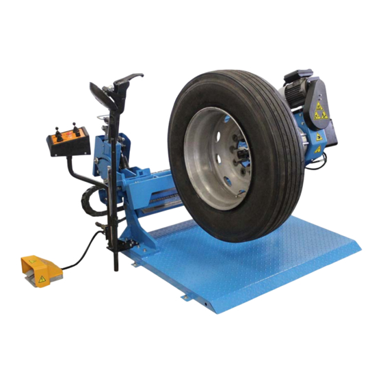
PRODUCT DESCRIPTION 1. Electric system 7. Foot pedal 2. Jaw 8. Hydraulic power unit 3. Chuck arm 9. Carriage 4. Tool roller 10. Tool holder arm 5. Self-centering chuck 11. Frame plate 6. Control unit TECHNICAL SPECIFICATION 2 HP 220V +/- 5% (209-231volts) 1 phase. Pump motor A 30 amp breaker is required. -
Page 7: Identifying Warning Signs
IDENTIFYING WARNING SIGNS Unreadable and missing warning labels must be replaced immediately. Do not use and add any object that could prevent the operator from seeing the labels. 7 / 41 REV. 01 2014... -
Page 8: Transportation And Unpacking
CHAPTER 3 – TRANSPORTATION AND UNPACKING TRANSPORTATION The machine must be transported in its original packaging and kept in the position shown on the package itself. 660KG The packaged machine may be moved by means of a fork lift truck of suitable capacity. -
Page 9: Installation
CHAPTER 4 – INSTALLATION INSTALLATION SPACE REQUIRED When choosing the place of installation, make sure that it complies with current safety at work regulations. The machine must be located on a flat floor of solid construction, preferably concrete. If the floor is uneven or broken, the machine will be not stable and the platform roller cannot move freely. -
Page 10: Electric Hook Up
ELECTRIC HOOK UP Any electric connection job must be carried out by professionally qualified personnel. Check to make sure the characteristics of your systems correspond to those required by the machine. The supply voltage (and main frequency) is given on the machine nameplate. It cannot be changed. -
Page 11: Operation
CHAPTER 5 – OPERATION 5.1 CONTROLS The control unit (fig. C) can be operated as follows: Do not permit the electric control panel to get wet! Joystick 1 (1/fig. C): Move it to position [a] to raise the chuck arm (3/fig. A). ... -
Page 12: 5.2 Correct Operation Checks
Joystick 2 (2/fig. C): Move it to position [a] to raise the tool holder arm (10/fig. A) out of working position. Move it to position [b] to lower the tool holder arm to the working position. Move it to position [c] to retract the tool roller (4/fig. -
Page 13: Locking The Wheel
LOCKING THE WHEEL When the chuck arm is lowered, there is always a potential for crushing anything in its movement range. Always work from position given in the instructions keep well out of working range of the various moving parts In locking the wheel, make sure that clamps are properly positioned on the rim, so as to prevent the tire from falling. -
Page 14: Light-Alloy Rim Locking
LIGHT-ALLOY RIM LOCKING The jaw protection kit CC-F100100 can be available upon request, are specially designed for operating on light alloy rims without damaging them. The protections are to be inserted (bayonet-like mounting) into the clamp support of the self-centering chuck (see fig. E/7). -
Page 15: 5.6 Mounting Tubeless Tires
Continue until the first bead is fully detached. To facilitate this operation, lubricate the bead and the edge of the rim with tire lubricant whilst the wheel is rotated. To avoid all risks, rotate the wheel clockwise when operating on the outside plane and anticlockwise when operating on the inside plane. -
Page 16: Ordinary Maintenance
CHAPTER 6 - ORDINARY MAINTENANCE Each maintenance operation must be effected only after the disconnection of the plug from electric network. Refer to the user and maintenance manuals for details on the routing maintenance of the generator and the compressor. To ensure that this tire changer works perfectly over the years, carry out the routine maintenance schedule described below: 1) Lubricate the following parts from time to time, after a thorough cleaning with naphtha:... -
Page 17: Trouble Shooting
CHAPTER 7 - TROUBLE SHOOTING ROUBLE OSSIBLE AUSE OLUTION Insert the plug correctly in its The power plug is not inserted. socket. After having switched on the power switch, the pilot lamp does not light on and no control No power from the mains Reset mains electric... -
Page 18: Moving, Storing And Scrapping
CHAPTER 8 – MOVING, STORING AND SCRAPPING MOVING THE MACHINE To move the machines, follow these instructions: 1) Completely fold down the tire changer. 2) Close completely the jaws of the chuck. 3) Unscrew the screws that secure the tire changer on the van. 4) Use a forklift truck of suitable loading capacity, take the tire changer off the van and put it away in a sheltered and covered place. -
Page 19: Optional Accessories
CHAPTER 9 – OPTIONAL ACCESSORIES The following optional accessories are available for the tire changer: CC-F100100 Set of 4 jaws for alloy rims Mounted on the jaws of the chuck, they are used to operate on alloy rims without damaging them. YC8-F200000 Pliers for alloy rims It is used to work with alloy rims without damaging them. -
Page 20: Hydraulic Scheme And Electric Diagram
CHAPTER 10 - HYDRAULIC SCHEME AND ELECTRIC DIAGRAM HYDRAULIC SCHEME Oil filter Pressure gauge Gear pump Stop valve Pump motor Stop valve Oil level plug Carriage cylinder Pressure overload valve Chuck arm cylinder Check valve Chuck opening/closing cylinder 2/2 solenoid valve normally open Tool moving cylinder Modular directional solenoid valve Tool tilting cylinder... - Page 21 ELECTRIC DIAGRAM 38V-400V/3PH Power main switch Circuit breaker Chuck motor Pump motor Contactor AC – clockwise direction Contactor AC – anticlockwise direction Contactor AC – emergency stop Pilot lamp Rectifier bridge Transformer Chuck switch Joystick 1 Joystick 3/foot pedal Joystick 2 Emergency stop knob Solenoid valve –...
-
Page 22: Parts List
PARTS LIST GENERAL BREAKDOWN GENERAL BREAKDOWN ITEM PART NO. DESCRIPTION C51B110000 Frame C51B300000B Self-centering chuck unit C51B010000 Guide support 0205013 Washer D.12 - GB/T97.1 0208009 Locking washer D.12 - GB/T93/ 0201148 Screw M12X40 - GB/T5783 0205008 Washer D.8 - GB/T97.1 0201026 Screw M8X16 - GB/T5783 22 / 41 REV. - Page 23 ITEM PART NO. DESCRIPTION C51B400000 Carriage unit C51BD12000 Control unit C51B000018 Chain protection 0201011 Screw M6X12 - GB/T5783 0205006 Washer D.6 - GB/T97.1 0202021 Screw M5X20 - GB/T70.1 C51B000016 Support C51B200000 Guide 0201185 Screw M20X90 - GB/T5783 C51B000005 Pulley spacer C51B000003 Chain pulley 0210054...
- Page 24 ITEM PART NO. DESCRIPTION 0203008 Nut M8 - GB/T6170 C51BY10000 Hydraulic power unit C51BD11000 Electric unit C51B000019 Power unit cover 304-ZW3070 Hydraulic hose L=3070 304-ZW3170 Hydraulic hose L=3170 304-ZW250 Hydraulic hose L=250 304-ZW3000 Hydraulic hose L=3000 304-WJ3200 Hydraulic hose L=3200 304-WJ1800 Hydraulic hose L=1800 0307042...
- Page 25 ITEM PART NO. DESCRIPTION 0310009 Seal 30X38X7 0309050 O-ring 70X3.1 C51AY38005 Cylinder guiding cover 0311005 Scraper 30X38X5/6.5 0204072 Nut M27X1.5 - GB/T812 C51B000014 Cylinder upper pin support C51AY42000 Carriage cylinder liner C51BY48001 Cylinder shaft 0215020 Greaser M10X1 0206041 Screw M5X12 - GB/T818 0508304 Pipe clamp M18 0505033...
- Page 26 SELF-CENTERING CHUCK UNIT SELF-CENTERING CHUCK UNIT ITEM PART NO. DESCRIPTION C51B300000A Chuck arm unit 0204029 Self-locking nut M20X1.5 - GB/T889.2 0205022 Washer D.20 - GB/T97.1 CC-580102 Cross piece CC-580103 Spacer CC-580101 Chuck opening control plate CC-580104 Spacer A 0205013 Washer D.12 - GB/T97.1 0204007 Self-locking nut M12 - GB/T889.1 CC-510204...
- Page 27 ITEM PART NO. DESCRIPTION C51B340000 Self-centering clamp unit C51B340001 Clamp arm CC-510203 0212002 Seeger D.16 0201118 Screw M18X1.5X80 - GB/T5785 C51B340002 Clamp lever 0202072 Screw M12X50 - GB/T70.1/12.9 CC-510102 Clamp support CC-510101 Clamp 0202060 Screw M10X20 - GB/T70.1 0202024 Screw M6X12 - GB/T70.1 0205006 Washer D.6 - GB/T97.1 CC-840100A...
- Page 28 CHUCK ARM UNIT CHUCK ARM UNIT ITEM PART NO. DESCRIPTION C51B310000 Chuck arm 0205011 Washer D.10 - GB/T97.1 0201064 Screw M10X25 - GB/T5783 CC-201010 Carriage slider 0209024 Screw M10X25 - GB/T77 0204012 Nut M10 - GB/T6172.1 0201050 Screw M10X35 - GB/T5781 28 / 41 REV.
- Page 29 ITEM PART NO. DESCRIPTION 0210037 Bush SF-1/11550 0309047 O-ring 145X3.1 CC-810101 Flange 0309012 O-ring 120X3.1 0202047 Screw M8X25 - GB/T70.1 CC-810104 End bearing CC-520100 Chuck turntable 0202079 Screw M10X35 - GB/T70.1 0213067 Pin 8X50 - GB/T120.2/ 0311006 Scraper 35X43 0305007 Guiding ring 35X10X2.5 C-2C120-85-9 Seal ring 35X45X2...
- Page 30 ITEM PART NO. DESCRIPTION YC8-3001010 Oil screen 0205006 Washer D.6 - GB/T97.1 0202024 Screw M6X12 - GB/T70.1 C51B300001 Cover 0205004 Washer D.5 - GB/T97.1 0202021 Screw M5X20 - GB/T70.1 C51B320000 Worm unit 0201068 Screw M10X40 - GB/T5781 CC-410101A Helical gear 0213025 Tab 8X30 - GB/T1096 0215024...
- Page 31 CARRIAGE UNIT CARRIAGE UNIT ITEM PART NO. DESCRIPTION C51B410000 Carriage C51B400010 Rubber pad CC-201010 Slider 0209024 Screw M10X25 - GB/T77 0205011 Washer D.10 - GB/T97.1 0201064 Screw GB/T5783/M10X25 0204012 Nut M10 - GB/T6172.1 31 / 41 REV. 01 2014...
- Page 32 ITEM PART NO. DESCRIPTION 0204008 Self-locking nut M16 - GB/T889.1 0205020 Washer D.16 - GB/T97.1 0202025 Screw M6X14 - GB/T70.1 C56B410005 Guide screw 0203004 Nut M6 - GB52 C51B430000 Hexagonal arm 0201200 Screw M16X80 - GB/T5782 C51B400008 Handle C51B400007 Positioning pin C56B412003 Spring C56B412002...
- Page 33 ITEM PART NO. DESCRIPTION 0303030 Banjo union 1/4 304-ZW3070 Hydraulic hose L=3070 0201101 Screw M16X100 - GB/T5782 304-ZW3170 Hydraulic hose L=3170 304-WJ3200 Hydraulic hose L=3200 BZ-720B-0401 Banjo bolt 304-ZW3000 Hydraulic hose L=3000 C51B400005 Cylinder lower pin BZ-GZ-003 Flow restrictor C51BY60000 Tool tilting cylinder unit C51B400006 Spacer B...
- Page 34 CONTROL UNIT CONTROL UNIT ITEM PART NO. DESCRIPTION C51BD12100 Support 0508277 Cable connector with 4 pins 0508350 Conduit connector M18 0511192 Cable conduit 15.8 0508282 Cable connector with 19 pins 0201136 Screw M3X10 - GB/T9074.4 0209042 Screw M6X8 - GB/T80 C51BD12001 Pivot pipe 34 / 41...
- Page 35 ITEM PART NO. DESCRIPTION 0206015 Screw M4X16 - GB/T818 C51BD12200 Casing 0205002 Washer D.4 - GB/T97.1 0203002 Nut M4 - GB52 0502044 Emergency stop knob 0505045 Manipulator C51BD12002 Casing cover C51BD12003 Control decal 0205004 Washer D.5 - GB/T97.1 0206024 Screw M5X10 - GB/T818 0502068 Chuck opening/closing switch 0507013...
- Page 36 HYDRAULIC POWER UNIT HYDRAULIC POWER UNIT ITEM PART NO. DESCRIPTION C51AY11000 Oil tank 0305010 Oil filter 3/8 0303007 Union 3/8 BZ-G18X40 Oil draining pipe 0301009 Gear pump 3.7cc BZ-BJ36 Pump joint 0309013 O-ring 115X3.55 BZ-ZB-V6 Manifold 0307067 Non return valve 0313057 Copper washer 16X20 36 / 41...
- Page 37 ITEM PART NO. DESCRIPTION 0307010 Pressure overload valve BZ-SD-01 Manifold plug 0309054 O-ring 17X2 BZ-DJ-1B Motor flange 0205006 Washer D.6 - GB/T97.1 0208005 Locking washer D.6 - GB/T93 0202033 Screw M6X20 - GB/T70.1 BZ-ZT24 Motor joint 0509026 220/380V/50/60HZ/1.5KW 4P 0209042 Screw M6X8 - GB/T80 W5-4+1 Multiple base with solenoid valves...
- Page 38 ELECTRIC UNIT ELECTRIC UNIT ITEM PART NO. DESCRIPTION C51BD11100 Complete casing 0511026 Gasket 0211001 Seeger D.3.5 – GB/T896 S551-6 0505025 Power switch 20A 0508019 Plug HP-22 0205006 Washer D.6 – GB/T97.1 0208005 Locking washer D.6 – GB/T93 38 / 41 REV.
- Page 39 ITEM PART NO. DESCRIPTION 0206031 Screw M6X10 – GB/T818 0203002 Nut M4 - GB52 0507118 Ferrule M20 0508012 Cable holder M27 0502023 Pilot lamp AC24V 0511169 Clamp 0507027 LED IN5408 C61AD11301 Component base plate 0508330 Guide 35X60 0206019 Screw M4X6 - GB/T818 0508330 Guide 35X200 0508006...
- Page 40 TOOLS AND ACCESSORIES TOOLS AND ACCESSORIES ITEM PART NO. DESCRIPTION C51B500000 Press roller unit C51B500001 Roller shaft C91A000002 Washer 0214038 Bearing 30212 C51B510000 Press roller C91A000003 Thread piece M45X1.5 CC-620000 Double tool unit 1 (Optional) CC-620001 Bead breaking disc pin CC-620002 Bead breaking disc bush CC-620003...
- Page 41 ITEM PART NO. DESCRIPTION CC-620200 Tool support CC-620004 Spring connection plate 0204011 Self-locking nut M27 - GB/T889.1 CC-620300A Short tool CC-620005 Spring 0204014 Nut M16X1.5 - GB/T6173 CC-620007 CC-F100100 Clamp protection kit 4 (Optional) CC-F100101 Clamp protection YC8-F100102 Plastic insert 1 YC8-F100103 Plastic insert 2 YC8-F100104...
Need help?
Do you have a question about the TTC305 and is the answer not in the manual?
Questions and answers