Table of Contents
Advertisement
Advertisement
Table of Contents

Summary of Contents for Nitehawk RAPTOR II
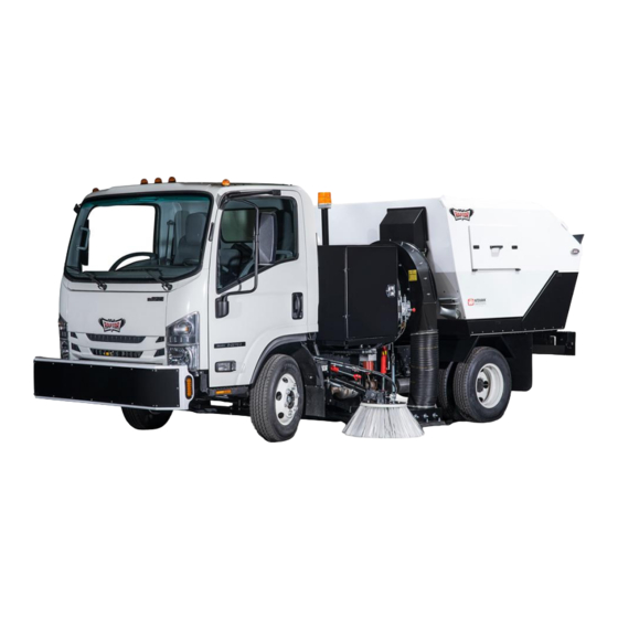
- Page 1 RAPTOR II OWNERS MANUAL...
-
Page 2: Table Of Contents
OPERATING PROCEDURES CONTROLS AND OPERATION SAFETY & LIGHTING VIDEO RESOURCES FOR OPERATING SWEEPER SERVICE AND MAINTENANCE DAILY INSPECTION SWEEPER MAINTENANCE SCHEDULE ANNUAL MAINTENANCE SERVICE & ADJUSTMENT GUIDES REPAIRS & TROUBLESHOOTING SUPPLEMENTS NITEHAWK WARRANTY SUMMARY ISUZU WARRANTY SUMMARY HYDRAULIC SYSTEM SCHEMATIC... -
Page 3: General Information
GENERAL INFORMATION ABOUT YOUR SWEEPER Congratulations on the purchase of your new NiteHawk Raptor II – the newest, most powerful and reliable sweeper on the market. Your sweeper has been designed to give you years of easy operation and trouble free service, with only a small amount of periodic maintenance. -
Page 4: Safety
SAFETY SAFETY STAND USE Your NiteHawk Sweeper comes from the factory with a Hopper Safety Stand. Never work under a raised hopper without a safety stand Always remove safety stand before lowering hopper or it may cause damage The stand must be used any time a person is working with the hopper in a raised position. Install the stand on one of the dump cylinders, accessing from behind the sweeper, and always secure the locking arm. -
Page 5: Safety Decals - Images And Locations
SAFETY DECALS – IMAGES AND LOCATION... -
Page 6: Replacement Parts
REPLACEMENT PARTS NiteHawk Sweepers use balanced and matched s ystem components for the entire sweeper s ystem. These parts are made and tested to NiteHawk specifications. Non-genuine or “will fit” parts do not consistently meet these specificati ons. The use of non-genuine or “will fit” parts may reduce Sweeper performance, void Sweeper warranties, and present a safety hazard. -
Page 7: General
GENERAL SAFETY INSTRUCTIONS AND PRACTICES A careful operator is the best operator. Safety is of primary importance to the manufacturer and should be to the owner/operator. Most accidents can be avoided by being aware of your equipment, your surroundings, and observing certain precautions. The first section of this manual includes a list of Safety Messages that, if followed, will help protect the operator and bystanders from injury or death. - Page 8 READ, UNDERSTAND, and FOLLOW the following Safety Messages. Serious injury or death may occur unless care is taken to follow the warnings and instructions stated in the Safety Messages. Always use good common sense to avoid hazards. Si no lee ingles, pida ayuda a alguien que si lo lea para que le traduzca las medidas de seguridad.
-
Page 9: Operator
OPERATOR SAFETY INSTRUCTIONS AND PRACTICES The operator of the Sweeper must be trained in the operation and safe use of this machine. The operator must read and completely understand the operator’s manuals of the Sweeper, Truck engine manufacturers. New operators should be trained in an open area clear of obstructions before operating public... - Page 10 Repeated or substantial breathing of hazardous dusts, including crystalline silica, could cause fatal or serious respiratory disease including silicosis. Concrete, masonry, many types of rock, and various other materials contain silica sand. California lists respirable crystalline silica as a substance known to cause cancer. Operation of this equipment under certain conditions may generate airborne dust particles that could contain crystalline silica.
- Page 11 Always wear a seat belt while driving the Sweeper during operation and transport. Serious injur y or even death could result from falling out of the Truck or from being involved in a collision. Start the Truck and Sweeper only when seated and belted in the Truck’s operator seat.
- Page 12 5. When operating in traffic, use the Sweeper’s directional indicator or signal lights to indicate your movement. Always use the Sweeper’s flashing signal lights and other equipped warning features to alert motorist of your presence and slow moving speed when sweeping in traffic. Be Aware of Traffic Around You and Watch Out for the Other Guy.
- Page 13 (oversized objects such as broken limbs and discarded tires). Such objects may plug the sweeping components and cause serious mechanical damage to the Sweeper. If possible, carefully place such objects out of the Sweeper and traffic path until properly removed by another means.
- Page 14 Use care when positioning the Sweeper to the dump station. Your vision, especially to the side and rear of the Sweeper may be reduced by the size of the Sweeper. Use side and rear view mirrors to aid vision. If you cannot see the dump site clearly, stop the Truck and examine the area.
- Page 15 Verbal communication near a Sweeper is difficult and dangerous. Operating instructions and sweeping directions should be made prior to starting the Sweeper. Unclear and misunderstood communication may lead to operator and bystander injury or death and equipment damage. If communication to a bystander is necessary, completely shutdown and exit the Sweeper.
- Page 16 Avoid body contact with collected debris in the hopper. Use protective clothing including gloves and eye protection when servicing or working in or around hopper. Collected debris in the hopper can cut or puncture resulting serious bodily injuries and the transmittal of diseases. Use extreme caution when operating the Sweeper in traffic.
-
Page 17: Maintenance
MAINTENANCE SAFETY INSTRUCTIONS AND PRACTICES Periodically inspect all moving parts for wear and replace when necessary with authorized service parts. Look for loose fasteners, worn or broken parts, and leaky or loose fittings. Make sure all pins have cotter pins and washers. Serious injury may occur from not maintaining this Sweeper in good working order. - Page 18 while the Truck engine is running. Completely shut down the sweeping components and the Truck engine and wait for all motion to come to a complete stop before servicing the Sweeper. Never leave the Sweeper unattended while the hopper bin is in the raised position.
- Page 19 to inflict serious injury. Never attempt to repair a pump or hose or tighten a connection while the system is pressurized. Always shut down the Truck engine and relieve water pressure by activating the system before performing any repairs to the high pressure water system NEVER work on or near any engine component that has generated heat until it has cooled down.
- Page 20 6. Store fuel and all oils at a site protected from moisture, dirt, and other contaminants Never run the Truck engine in a closed building or without adequate ventilation. The exhaust fumes can be hazardous and deadly to your health. If it is necessary to run the Truck engine in an enclosed area, remove the exhaust fumes from the area to the outdoors with an exhaust pipe extension.
- Page 21 transmission in park and set the parking brake. Turn the Truck engine off and remove the keys to prevent inadvertent or accidental starting of the engines. Unexpected engine start up or truck movement can result in serious bodily injuries or death. Do not inspect or approach the sweeper fans while they are rotating.
-
Page 22: Laws And Regulations
LAWS AND REGULATIONS This section is intended to explain in broad terms the concept and effect of federal laws and regulations concerning employer and employee equipment operators. This section is not intended as a legal interpretation of the law and should not be considered as such. Employer-Employee Operator Regulations U.S. - Page 23 7. Provide the required tools to maintain the Sweeper in a good safe working condition and provide the necessary support devices to secure the equipment safely while performing repairs and service. Require that the employee operator stop operation if bystanders or passersby come within 25 feet.
-
Page 24: Sweeper System Descriptions & Indentification
SWEEPER SYSTEM DESCRIPTIONS & INDENTIFICATION SWEEPER COMPONENTS 1. Rear Bumper 2. Sweeping Head 3. Curb Broom (if equipped) 4. Heavy Duty Front Bumper (if equipped) 5. In Cab Controls 6. Tool Box (if equipped – Vertical Style Shown) 7. Safety Beacon 8. - Page 25 1. Rear Toolbox 2. Hoper Side Door 3. Hopper Intake Tube 4. 10” Flex Intake Hose 5. Sight Gauge – Hydraulic Fluid 6. Hydraulic Fluid Reservoir 7. Water Reservoir (if equipped) 8. Battery 9. Toolbox (if equipped – Vertical Style Shown)
- Page 26 Pickup Head, Driver Side 1. Pickup Head Cylinder 2. Upstop Pad 3. Upstop 4. Skid Plate 5. Skid Plate Bolt 6. Skid Bolt 7. Skid (Double Row Tungsten) 8. Pickup Head Spring 9. Skid Spacer 10. 10” Flex Intake Hose...
-
Page 27: Hydraulic System
HYDRAULIC SYSTEM This section will take you through the entire hydraulic system, front the front of the truck to the back, identifying all major components Hydraulic System, Engine Compartment 1. Hydraulic Lines – Proportioning Valve 2. Proportioning Valve 3. Pump Belt 4. - Page 28 Hydraulic System, Driver Side, Behind Cab 1. Main Pump to Pressure Filter Line 2. Curb Broom Lines 3. Reservoir to Pump Supply Line (Suction Line) 4. Hydraulic Reservoir 5. Pressure Filter to Manifold Line 6. Pickup Head Cylinder Upper Port (Lowers Head) 7.
- Page 29 Hydraulic System Manifold, Driverside, Top View 1. 10” Flex Exhaust Tube 2. Manifold to Fan Motor Pressure Line 3. Curb Broom Pressure Relief Valve 4. Curb Broom Flow Control Valve 5. Pressure Filter to Manifold Pressure Line 6. Pressure Filter Housing 7.
- Page 30 Hydraulic System Manifold, Driver Side, Bottom View 1. Dump Cylinder Lines 2. Controller 3. Pickup Head Cylinder Lines 4. Pickup Head Cylinder Lines 5. Curb Broom Lines 6. Accumulator to Manifold Pressure Line 7. Fan Motor Line 8. Fan Motor...
- Page 31 Hydraulic System Reservoir, Passenger side, Top View 1. Reservoir to Pump Supply Line (Suction Line) 2. Hydraulic Fluid Reservoir 3. Reservoir Sight Gauge 4. Low Pressure Filter Housing 5. Case Drain Line (Pump Body to Reservoir) 6. Reservoir Breather Filter 7.
- Page 32 Behind Back Drop Down Door – Rear Sweeper Accumulator – If Curb Broom only 1. Counterbalance Valve (same on left and right) 2. Dump Cylinder 18” (same on left and right) 3. Dumpster Bracket Bumper HYDRAULIC SYSTEM – INDICATORS Pressure Filter – the clear disc on top will turn red if the filter is clogged and being bypassed Return Filter –...
-
Page 33: Optional Equipment (Curb Broom / Water System)
In order to minimize amount of time spent with back pack blower cleaning a parking lot, you can equip your NiteHawk Raptor II with a curb broom. For proper curb broom usage, please refer to the “CONTROLS AND OPERATION” section of the manual. See below for component call outs. - Page 34 DUST SUPRESSION SYSTEM To increase the efficiency of your sweeper and reduce the amount of dust generated by the vacuum system, a water spray system can be added to your NiteHawk Sweeper Water System, Reservoir The water system is equipped with a 100 gallon tank mount directly behind the cab.
- Page 35 Water System Nozzles (5 Front Spray Bar, 1 Curb Broom, 1 Driver Side Sweeping Head, 1 Passenger Side Sweeping Head)
-
Page 36: Operating Procedures
OPERATING PROCEDURES CONTROLS AND OPERATION Your new NiteHawk Raptor II has the latest in highly reliable, rugged, simple, easy to use controls to control all sweeping functions on your Sweeper with a Heads Up Display. OPERATING REMINDER The Raptor II must be in “Sweep Mode”... - Page 37 SWEEP MODE / ROAD MODE (5) Press this button once to turn on “Sweep Mode” and once to turn off “Sweep Mode” You will see “Sweep Mode” or “Road Mode” in the Heads Up Display depending on your selection SWEEPER POWER SETTINGS (10 and 15) Press button 10 to raise sweep power / hydraulic pressure.
-
Page 38: Safety & Lighting
For all sweeper operations, it is highly recommended that operators use all safety lighting options Standard Safety Beacon (standard) – Center mounted, available to them: This can include: LED Light Bar – Center Mount (optional), LED Bumper Flashers (optional), Chassis Warning Flashers (standard) VIDEO RESOURCES – SWEEPER OPERATION NiteHawk Sweepers YouTube Channel https://www.youtube.com/user/nitehawksweepers11... -
Page 39: Service And Maintenance
SERVICE & MAINTENANCE DAILY INSPECTIONS (PRE/POST OPERATION) Never allow the sweeper to operate with no fluid registering on the sight glass. This will void your warranty and may cause severe damage to your hydraulic system. -
Page 40: Sweeper Maintenance Schedule
RECOMMENDED SERVICE SCHEDULE... -
Page 41: Annual Maintenance
ANNUAL MAINTENANCE REPLACING HYDRAULIC FLUID AND FILTERS: Never replace hydraulic fluid when the engine or truck exhaust system is hot or warm. 1. Remove the drain plug located on the bottom of the hydraulic reservoir. 2. Completely drain all the fluid and replace the plug. 3. - Page 42 6. Unscrew the red filter bowl, remove and replace with a Pressure Filter Element (PN – HY- 1355) and reinstall to upper housing. Remove and replace the red breather filter (Part Number HY-1202) on top of reservoir...
- Page 43 Refill the hydraulic reservoir to the center of the site gauge with AW 46 hydraulic fluid. Do not run the pump until the reservoir has been refilled. This will void your warranty and could cause severe damage to your hydraulic system. 9.
-
Page 44: Service & Adjustment Guides
SERVICE AND ADJUSTMENT GUIDES FLAP ADJUSTMENT For optimal sweeping performance, the flaps adjustment should be performed anytime a gap greater than ¼” is worn between bottom of back flap and flat/level ground. Primary Flap Adjustment 1. Power up sweeper and lower the sweeping head to ground 2. - Page 45 Secondary Flap Adjustment 1. To maximize life span of sweeping flaps, NiteHawk designed in a secondary adjustment system when you have reached limits of the Primary Flap Adjustment 2. Keep the sweeping head in the up position 3. Loosen the 3 skid bolt nuts, remove skid 4.
- Page 46 FLAP REPLACEMENT When a ¼” gap appears between the rubber flaps and the pavement and, there is no more adjustment in the skid plates and there is only 1 skid spacer remaining, it is time to change the flaps. In order to change the flaps the pick-up head must be removed from under the truck. 1.
- Page 47 RELIEF VALVE ADJUSTMENT - HOPPER The relief valve is factory preset to lift 900 lbs. and should only be adjusted if all other possibilities have been exhausted. Before you adjust the relief valve you should check to see if the hopper is overloaded.
- Page 48 CURB BROOM ADJUSTMENT (IF EQUIPPED) Refer to the “Controls and Operation” section for operational use of curb broom. ALWAYS USE CURB BROOM AT 100% POWER SETTINGS FOR OPTIMAL PERFORMANCE A Hydraulic cylinder located along the truck frame operates the broom arm. The broom follows a fixed axis.
- Page 49 EXTENSION / RETRACTION The curb broom turnbuckle adjusts how far the broom extends and retracts. Adjusting how far the broom extends also affects how far the broom retracts and vise versa. To extend the broom further, unbolt the turnbuckle body from the curb broom arm, rotate the turnbuckle body around the threaded washer –...
- Page 50 BROOM SPEED The speed of the broom is factory preset, but it can be adjusted, using the curb broom relief valve to fit your individual needs. The curb broom relief valve is located on the driver side of the unit on the curb broom valve assembly.
- Page 51 BROOM REPLACEMENT 1. Loosen and remove curb broom dish bolts 2. Remove 2 segments of curb broom 3. Verify there are 3 nylock nuts installed in each segment of curb broom 4. Install new segments and tighten bolts, mark bolts with paint pen for ease of visual inspection...
- Page 52 DUST SUPRESSION SYSTEM (IF EQUIPPED) The dust suppression system keeps surface dust to a minimum by misting water along the sweeping path. Each system has 7 or 8 nozzles, a water pump, strainer, drain and tank. The tank holds approximately 100 gallons There are five nozzles located along the front bumper of the truck, two nozzles mounted near the head on each side of the unit, and one nozzle mounted near the broom, if equipped.
- Page 53 LUBRICATION - FAN BEARINGS Do not attempt to lubricate or adjust the blower fan while the fan is turning. The fan spins at a high RPM and is dangerous. The fan bearings only require minimal lubrication to keep them spinning quiet and effective.
-
Page 54: Repairs & Troubleshooting
O-ring. The hydraulic system on your NiteHawk Sweeper is vented so it is not uncommon to have a mist of fluid on top of your reservoir; this can sometimes be mistaken for a leak. If a leak does occur call the NiteHawk Service Line at 1-800-448-9364. MANUAL OVERRIDES All models are equipped with manual override buttons on each directional valve. - Page 55 Be sure to have everything clear around moving parts prior to operating manual overrides. To lift the override button, insert a small narrow tool into the opening on the red override button and pull up. This works for both curb broom and pickup head directional valves Simply push and hold down on the button to operate valve in other direction.
- Page 56 Hopper Manual Override – Use a small screwdriver HYDRAULIC LINE REPLACEMENT Do not replace hydraulic lines with the hopper in raised position, or with the hydraulic system running. Removing a hydraulic line with the hopper up could cause the hopper to drop causing severe injury or death. Always pull out the accumulator relief valve (large red handle on side of hydraulic manifold) prior to doing any work to the hydraulic system If you must replace a hydraulic line with the hopper raised always use a safety stand.
- Page 57 TROUBLESHOOTING CHECKLISTS Pick-up head or hopper will not raise or lower 1. Power Level is too low - increase power level 2. Check for external hydraulic leaks 3. Valve sticking - check manual overrides 4. Check relief valve, adjust if necessary 5.
- Page 58 6. Check for missing weights-- Check for missing weights by visual inspection. Remove the blast hose and inspect each fan blade. Replace fan turbine if needed. Fan does not spin after raise in pressure 1. Remove inspection cover on fan motor adapter. Inspect fan coupler for wear and excessive play –...
-
Page 59: Supplements
SUPPLEMENTS SWEEPER WARRANTY NiteHawk Sweepers Warranty Summary Raptor II WARRANTY LIMITATIONS (time or mileage, whichever comes first)* Time Mileage Main Hydraulic Pump ( Piston) 0-60 months Unlimited Compensator 0-60 months Unlimited Fan Motor 0-60 months Unlimited Curb Broom Pump 0-60 months... - Page 60 COVERED LED Lights Lifetime Please note: This is only a summary of the NiteHawk Sweepers limited warranty. Complete and current information may be found in your Sweeper's Owner's Manual. Specifications subject to change without notice. * The warranty coverage is determined by the mileage of the vehicle and the number of months from the delivery date.
-
Page 61: Isuzu Warranty Summary
CHASSIS WARRANTY This data is for informational purposes only. Please refer to your chassis owner’s manual for most accurate warranty descriptions Isuzu Warranty Information: N-Series Gas PERCENTAGE NPR VEHICLE COVERAGE WARRANTY LIMITATIONS OF DEALER'S (time or mileage, whichever comes first)* NORMAL CHARGE PAID BY... -
Page 62: Hydraulic System Schematic
HYDRAULIC SCHEMATIC Main Hydraulic Pump 2. Proportioning Valve 3. Curb Broom Cylinder 4. Curb Broom Motor 5. Curb Broom Check Valve CHASSIS ENGINE 6. Pressure Filter 7. Manifold 8. Fan Motor DISPLAY 9. Fan / Motor Coupling KEYPAD 10. Suction Filter 11. - Page 63 RAPTOR II HYDRAULIC SCHEMATIC...
Need help?
Do you have a question about the RAPTOR II and is the answer not in the manual?
Questions and answers
We hard a loud bang then after that the hydraulic pressure **** failed to turn. What could be the problem?
A loud bang followed by hydraulic pressure failure in a NiteHawk RAPTOR II could indicate a sudden component failure. Possible causes include:
1. Ruptured Hydraulic Hose or Fitting – Hydraulic hoses and fittings may have failed due to pressure buildup, leading to loss of hydraulic fluid.
2. Failed Main Hydraulic Pump – If the main hydraulic pump or compensator failed, it could result in pressure loss.
3. Blown Check or Switching Valve – A damaged check or switching valve may prevent proper hydraulic flow.
4. Breather Filter Malfunction – If excessive pressure built up and the breather filter failed to release enough hydraulic fluid mist, a sudden failure could occur.
5. Seized Bearings in the Fan Motor – If the fan bearings seized, the hydraulic system may have experienced excessive strain, leading to failure.
A visual inspection of hoses, fittings, fluid levels, and key hydraulic components is recommended to diagnose the issue.
This answer is automatically generated
where is the the resetable link for controll panel i have no power
If the hopper fills with water while sweeping how do you drain the water without garbage debris running out