Table of Contents
Advertisement
Advertisement
Table of Contents

Related Manuals for Rilon MIG/NBC 300GN

Summary of Contents for Rilon MIG/NBC 300GN
- Page 1 USER MANUAL MIG/NBC 300GN...
-
Page 3: Table Of Contents
CONTENTS 1. SAFETY WARNING 2. PRODUCT DESCRIPTION 3. TECHNICAL PARAMETERS 4. INSTALLATION INSTRUCTION 5. PANEL FUNCTION ILLUSTRATION 6. OPERATION PARAMETER RECOMMENDATION 7. STRUCTURE CHART AND MAJOR PART LIST 8. CIRCUIT DIAGRAM ATTENTIONS & PREVENTIVE MEASURES 10. POTENTIAL OPERATING PROBLEMS 11. DAILY MAINTENANCE 12. -
Page 4: Safety Warning
SAFETY WARNING ● Please read this manual carefully before using it. ● The safety notes listed in this manual is to ensure correct use of the machine and to keep you and other people from being hurt. ● The machine is safety considered designed, please refer to the safety warning listed in the manual when using it in case of bad accidents. - Page 5 7. Do not use broken or wet insulation gloves. 8. Use safety net when work at high position. 9. Check and maintain regularly, don’t use it until the broken parts are fixed well. 10.Cut off all the input power when not use. 11 ....
- Page 6 *Toppling over of the gas cylinder will cause body hurt. * Wrong use of the gas cylinder will lead to high-pressure gas eruption and cause human hurt. 1.Use the gas cylinder correctly. 2.Use the equipped or recommended gas adjustment. 3.Read the manual of the gas adjustment carefully before using it, and pay attention to the safety notes. 4.Fix the gas cylinder with appropriate holder and other relative parts.
- Page 7 Correct False Lifting way for gas shielded machines Notes for electromagnetism disturb: 1. It may need extra preventive measures when the power is used in some partial space. 2. Before the installation, please estimate the potential electromagnetism problems of the environment as follows: a)Upper and down parts of the welding equipments and other nearby power cable, control cable, signal cable and phone cable.
-
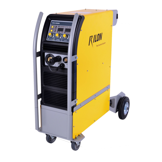
Page 8: Product Description
PRODUCT DESCRIPTION The welding machine applies the most advanced inversion technology in the world. The principle of inversion is to transform the power frequency of 50Hz/60Hz into direct current and invert it into high frequency through high-power device IGBT, then perform voltage-drop and commutation with the output high-power D.C power supply via Pulse Width Modulation (PWM). -
Page 9: Technical Parameters
TECHNICAL PARAMETERS Type MIG/NBC 300GN Item Power voltage (V) 3 phase 400V±15% Frequency (Hz) 50/60 Rated input current (A) MIG :18.5 MMA :20.5 Output current adjustment (A) MIG :50-300 MMA :70-300 Output voltage (V) MIG :16.5-29 MMA :22.4-32 Duty cycle (%) -
Page 10: Installation Instruction
INSTALLATION INSTRUCTION The welding equipment is equipped with power voltage compensation device. It keeps the machine work normally when power voltage fluctuating ±15% of rated voltage. When using long cable, in order to reduce voltage drop, big section cable is suggested. If the cable is too long, it will affect the performance of arcing and other system function, it is suggested to use the recommend length. - Page 11 Explanatory drawing for Installation of 300GN: MIG/NBC Power supply Three phase~AC400V meter Gas cylinder Earth clamp Workpiece Welding gun Notes: Turn the welding machine to MMA mode for heating the gas cylinder to prevent CO meter icing when the machine is not working under MIG mode. USER MANUAL YF-20Y A1...
-
Page 12: Panel Function Illustration
PANEL FUNCTION ILLUSTRATION Front panel instruction: Current adjustment button Arc trait adjustment button MMA/MIG switch button 2T/4T switch button Abnormal indicator Current meter Remove control indicator Voltage meter Voltage adjustment button Negative output terminal Positive output terminal Polarity conversion joint Torch joint USER MANUAL YF-20Y A0... - Page 13 1. Change-over button 1) MMA/MIG change-over button: the machine is under MIG mode as defaulted when it is turn on, and the MIG indicator is on. Press the MMA/MIG button, it it changed to MMA mode. It is turned back to MIG by repeat the step above.
-
Page 14: Operation Parameter Recommendation
OPERATION PARAMETER RECOMMENDATION The values listed in the following table are the general specification values under standard condition. Plate Wire Interval Current Voltage Welding Wire Gas flow thickness diameter (mm) speed extension rate (mm) (mm) (cm/min) (mm) (L/min) 0.8,0.9 60~70 16~16.5 50~60 0.8,0.9... - Page 15 Plate Wire Welding Current Voltage Welding Wire Gas flow thickness diameter speed extension rate (mm) (mm) vertical (cm/min) (mm) (L/min) angle(°) 0.8,0.9 70~80 17~18 50~60 10~15 0.9,1.0 85~90 18~19 50~60 10~15 1.0,1.2 100~110 19~20 50~60 10~15 1.0,1.2 115~125 19~20 50~60 10~15 1.0,1.2 130~140...
-
Page 16: Structure Chart And Major Part List
STRUCTURE CHART AND MAJOR PART LIST Structure Chart of MIG/NBC 300GN USER MANUAL YF-20Y A1... - Page 17 Major parts list of MIG/NBC 300GN Item Quantity Item Quantity Wire check switch Discal axis Erect clapboard Heater board Main control board Wire feeder structure EMC board Push/lock button Horizontal clapboard Left upper cover Fuse seat Panel preventive cover Support of argon cylinder...
-
Page 18: Circuit Diagram
CIRCUIT DIAGRAM MIG/NBC 300GN 15R/10W 472/3KV*2 200A/400V Top board 200A/400V Current transformer Commutate board Input 14.4A 472/3KV*2 PCON6 Output reactor PCON1 300A Output+ AC380V 14.4A Brachium capacitance 15R/10W Port EMC board PCON2 15R/10W AC380V 472/3KV*2 14.4A PCON3 PCON8 AC380V 200A/400V... -
Page 19: Attentions & Preventive Measures
ATTENTIONS & PREVENTIVE MEASURES 1. Environment 1) The machine works in environment where air conditions are dry with a dampness level of max 90%. 2) Ambient temperature should be between -10 to 40 degrees centigrade. 3) Avoid welding in sunshine or raining. Avoid water entering the machine 4)... -
Page 20: Potential Operating Problems
POTENTIAL OPERATING PROBLEMS The phenomenon listed below may happen due to relevant accessories used, welding material, surroundings and power supply. Pleas improve surroundings and avoid these problems.. A. Arc starting difficulty. Arc interruption happens easily: 1) Examine whether grounding wire clamp contacts with the work pieces well. 2) Examine whether each joint has improper contact. -
Page 21: Daily Maintenance
DAILY MAINTENANCE WARNING! The power shall be cut off completely before all maintenance, repairing works. Make sure to pull out power plug before opening the case. Remove dust regularly with dry compressed air. If the welding machine is used in surroundings with heavy smoke and polluted air, it is necessary to remove dust at least one time one month. -
Page 22: Troubleshooting And Fault Finding
TROUBLESHOOTING AND FAULT FINDING Notes: The following operations must be performed by qualified electricians with valid certifications. Before maintenance, you are suggested to contact local distributor to verify qualification. Malfunctions Solution The meter show nothing; Confirm the power switch is on. Fan does not rotate;... -
Page 23: Initial Problems Diagnose
INITIAL PROBLEMS DIAGNOSE Even the machine comes up with abnormal phenomenon such as welding unable, arc unstable or bad welding effect, it is still early to judge that there is malfunction on the machine. The above-mentioned abnormal phenomenon may be caused by some reasons. For example: tight parts loosen, forgetting to switch on, wrong set up, cable broken and gas rubber pipe cracked, etc. - Page 24 Abnormal Items Area and Item to be inspected and maintained Wire Feeding Wire feeding wheel does not match 〇 〇 〇 〇 〇 Device with the diameter of wire in texturing tube Crackle on wire feeding wheel, groove blocked up or defect Too tight or loose of the handle Wire powder accumulated on the inlet of SUS pipe...
-
Page 25: Daily Checking
DAILY CHECKING WELDING POWER SUPPLY Position Check points Remarks Control panel 1. Switch condition of operation, transfer and installation 2. Test the power indicator Cooling fan 1. Check if there is wind and the sound normal or not If abnormal noise and no wind, please check the inner Power part 1. - Page 26 WIRE SENDING MACHINE Position Checking keys Remarks Pressing arm If put the arm to the suitable indicating level Lead to unstable arc and wire sending Wire lead tube If powder or residue store up in the mouth of the Clean the residue and check the reason tube and solve it Wire diameter and the tube inner diameter...
Need help?
Do you have a question about the MIG/NBC 300GN and is the answer not in the manual?
Questions and answers