
Summary of Contents for TGE TGWS10-24
- Page 1 *Please read the manual before installation Professional Wind & Solar Hybrid Controller Manual...
-
Page 2: Table Of Contents
1. Notes : Thank you very much for purchasing our controller, please read the user manual carefully before installation and use the product and keep it with due care. Receive the product should first check whether the controller is damaged during the transportation. If you found the problem, please contact our company or the transport company immediately. -
Page 3: Technical Specification
Technical Specification Item No. TGWS10-24 TGWS10-48 Rated Battery Voltage Rated Wind Turbine Power Maximum Wind Turbine Input Power 1.5kW Rated Solar Charge Current Over-discharge Voltage 20.4V(adjustable) 40.8V(adjustable) Over-discharge Recovery Voltage 23.0V(adjustable) 46.5V(adjustable) Over-charge Voltage 29.4V (adjustable) 58.8V(adjustable) Over-charge Recovery Voltage 26.4V(adjustable) - Page 4 Item No. TGWS14-24 TGWS15-48 TGWS20-96 TGWS20-120 TGWS20-220 TGWS20-240 Rated Battery Voltage 120V 220V 240V Rated Wind Turbine Power Maximum Wind Turbine Input Power Rated Solar Charge Current 20.4V(adjust 40.8V 80.0V 102V 185V 204V Over-discharge Voltage able) (adjustable) (adjustable) (adjustable) (adjustable) (adjustable) Over-discharge Recovery 23.0V(adjust...
- Page 5 Item No. TGWS20-48 TGWS20-96 TGWS20-120 TGWS20-220 TGWS20-240 Rated Battery Voltage 120V 220V 240V Rated Wind Turbine Power Maximum Wind Turbine Input Power Rated Solar Charge Current 40.8V 80.0V 102V 185V 204V Over-discharge Voltage (adjustable) (adjustable) (adjustable) (adjustable) (adjustable) Over-discharge Recovery 46.5V 92.0V 115V...
- Page 6 Item No. TGWS30-48 TGWS30-96 TGWS30-120 TGWS30-220 TGWS30-240 Rated Battery Voltage 120V 220V 240V Rated Wind Turbine Power Maximum Wind Turbine Input 4.5kW Power Rated Solar Charge Current 40.8V 80.0V 102V 185V 204V Over-discharge Voltage (adjustable) (adjustable) (adjustable) (adjustable) (adjustable) Over-discharge Recovery 46.5V 92.0V...
-
Page 7: Universal Function
4. Universal Function 4.1 Adaptive Impedance Matching of Wind Turbine & Load Wind Turbine , battery and load all have internal resistance. According to impedance matching principle, only when Input. impedance equals to output impedance, power utilization would be maximal , The energy utilization will be improved to the utmost extent by adaptive impedance matching of controller . -
Page 8: Optional Function
5 .Optional Function 5.1 Optional Function 1 : Boost Function Wind turbine output voltage intelligent boost The boost module starts automatically when the wind turbine voltage is lower than battery voltage , ensure that the wind turbine normally charges the battery. The boost module shuts off automatically when the wind turbine voltage is higher than battery voltage. - Page 9 5.4 Optional Function 4 : RS Communication RS232 or RS485 real time communication With serial port communication . User can analyse the data from the software installed in the computer. Procedure could be upgraded by RS232 Some customization functions could be altered through upgrad procedure by serial ports. PC and controller both could set parameters 5.5 Optional Function 5 : USB data logging function All data can be stocked into 8GB USB flash disk .
-
Page 10: Design & Dimension
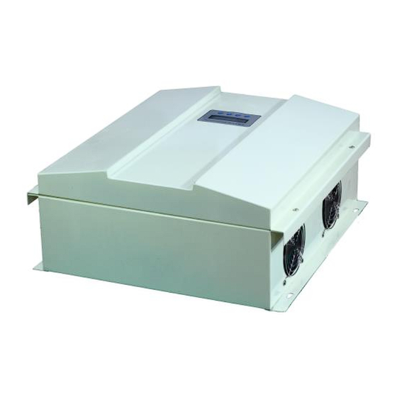
6. Design & Dimension 6.1 Design... - Page 11 6.2 Dimension...
-
Page 12: System Schematic
7 System Schematic Solar Panel Wind Turbine Battery 8 Installation 8.1 Warning Pls read this chapter carefully before installation. To make sure the whole process is safe . It is important to choose the installation location for controller. Keep the controller away from rain, insolation , put the controller in dry ,ventilated place . -
Page 13: Electrical Connection
9 Electrical Connection 9.1 Terminal 9.2 Connection steps Pls do the connections safely and strictly according to the steps below Before connection . Pls put “ BATTERY” Switch to “ OFF” . Then , conect battery to Step 1 : Controller’s “... -
Page 14: Default Interface
10.2 Display on LCD Screen Default Interface Power on 1 Battery power: * % stands for battery power range Low : Battery low voltage , Normal :Battery normal voltage Full : Battery full voltage , Float : Battery floating voltage Menu V: **V Ft **S : The countdown of exiting from floating charging... -
Page 15: Main Menu Interface
Main Menu 1 SystemInfo Addition 1 ****-**-** Year-Month-Day USBOK :USB normal, USBNC : USB un-connected USBdERR: USB module fault or un-connected USBFULL : USB flash disk full **-**-** : Hour- Minute-Second ****-**-** If you don’t buy the USB data logging function ,Don’t have this menu USB** **-**-** Menu... -
Page 16: System Interface
10.4 Display on LCD Screen System Information Battery capacity numeric flickers. Menu Press to increase/decrease the Main Menu Menu 1 . System Info value. Press “Menu” , saved; Press “Esc” , not 1 .System Info Batt: ** Ah saved. “ ADD ”or “CLEAR” “ flickers. to select “ADD”... -
Page 17: Wind Information
10.5 Display on LCD Screen Wind Information Menu Menu Main Menu 2. Wind Info 2. Wind Info MPPT : ON Wind turbine maximum limiting rotate speed numeric Menu flickers. Pres to increase/decrease the 2. Wind Info value .Press “Menu” , saved; Press “Esc” , not saved. Rota : **R Wind turbine magnetic pole numeric flickers. -
Page 18: Solar Information
10.6 Display on LCD Screen Solar Information “ON” or “OFF” flickers. Press Menu to select Main Menu Menu 3 . Solar Info “ON” or “OFF”. Press “Menu” , saved; 3 .Solar Info M-SW : ON 1/1 Press “Esc” , not saved. ON: Solar charging is on;... -
Page 19: Pc Software Introduction
PC Software Introduction 11.1 Software File : Customer can use this software without installation. The RAR file includes ,database file, user files, detail file and etc. are placed in the same directory. As the picture below: 11.2 Open the software: Step 1 : Customer should connect the controller with battery or power supply to start the controller at first Step 2 : Connect PC and the controller with serial cable . - Page 20 11.3 Software Connection configuration : Click “Setting” at first, click “Serial Port Setting” secondly, then serial port number and baud rate could be set. As below: Remark : If workable port of the computer is COM 2 or COM 3 .customer should set the serial port as COM2 or COM 3. Means customer should set the serial port as the real workable port according to their computer.
- Page 21 11.5 Data maintenance: User could view and analyze the history data by Clicking “File (F)”, then clicking “View History Data”. User could view the data of any time, just by choosing “Start Time” and “End Time”. Also could be used to check more accurate time.
- Page 22 Select time then click “OK”, the selected data will be backup to the folder “data”. Data is displayed by table form so that make analysis easier. 11.6 About Controller: Click “Help (H)” and “About (A)”, you will get product’s information. 11.7 Quitting Software: Click “File (F)”, and then click “Exit (X)”.
-
Page 23: The Warranty & Maintenance
12 The Warranty & Maintenance 12.1 Warranty We provide one year warranty since delivery. If the product is exceed warranty or damaged by transportation, improper use, human elements, force majeure, it is not under warranty. 12.2 Maintenance The installation and storage should avoid the highly corrosive, high dust, high temperature, and high humidity environment;... - Page 24 Hefei Top Green Energy Technology Co.,LTD Website: www.top-green.cn Tel:86 -0551-65765201 Fax: 86- 0551-65765203 Email : info@top-green.cn Version 2.0...
Need help?
Do you have a question about the TGWS10-24 and is the answer not in the manual?
Questions and answers