
Subscribe to Our Youtube Channel
Related Manuals for AGS 900


Summary of Contents for AGS 900
- Page 1 pg 1...
- Page 2 Page IMPORTANT INSTALLATION INSTRUCTIONS WARNING-To reduce the risk of severe injury or death: 1) READ AND FOLLOW ALL INSTALLATION INSTRUCTIONS. 2) Make sure that the gate is properly installed. An improperly installed door could cause severe injury. Have a qualified service person make repairs to the gate and other hardware before installing the opener.
-
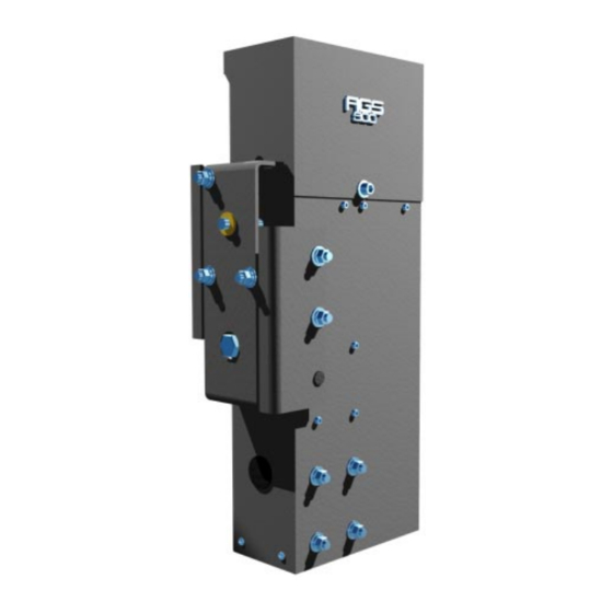
Page 3: Overall Dimensions
OVERALL DIMENSIONS: Height: 23" (58 cm) Length: 11" (28 cm) Width: 8" (20 cm) SHIPPING WEIGHT: OPERATOR:53 lbs CHAIN PACKAGE:12 lbs MOUNTING POSTS:16 lbs TOTAL: 81 lbs (37 kg) OPTIONS: OPERATOR + BATTERY BACK-UP PACKAGE: 59 lbs (27 kg) LOW VOLTAGE CABLE: 1 lbs/10 ft (.149 kg/m) CONCRETE MOUNTING STAND: 17 lbs (8 kg) POWER REQUIREMENT: Dedicated 115 VAC (+/- 10V) , 5A Power Circuit... - Page 4 Another possibility for supplying power to the operator is with the low voltage battery back-up version of the AGS 900. To supply power to the AGS 900 battery back-up, wire as small as 16 gauge can be run as far as 300 feet from a charger that is plugged in remotely. Because the power is low 12 Volt DC, the wire can be direct burial wire which eliminates the need for expensive conduit runs.
- Page 5 All that is needed to supply power to a battery back-up version of the AGS 900 is some inexpensive low voltage burial cable. If the cable is 16 gauge it can be run as far as 300 feet. For solar versions of the AGS 900, no power needs to be run to the operator.
-
Page 6: Auto Close Timer
PULSE OPEN INPUT The Pulse Open input feature is an open input on the circuit board which will increase the security of the AGS 900 gate operator system. When an open input device such as a radio receiver is connected to the Pulse Open input, and the radio transmitter is pressed, the gate operator will activate but will then ignore the input if the input is prolonged. - Page 7 pg 7...
- Page 8 SCREW, SOCKET HEAD CAP, 10-32 X 1" NYLON WASHER 3/8" ID FOR COVER SCREW LIMIT PLATE COMPRESSION SPRING ALLEN WRENCH, 5/16" LOCKNUT, 8-32 NYLON INSERT, HEX AGS 900 LOGO, DIE CAST ZINC TRANSFORMER (115 V MODELS ONLY) STICKER, WEATHER CONTROL BOARD (FULL SYSTEMS OPTIONAL) STICKER, CAUTION HEX STANDOFF, 6-32 X 1/2"...
- Page 9 The tail end of the gate should extend approximately 18 inches beyond the edge of the driveway. If this is not the case, an extension tail will need to be added to the gate. This will give room for the gate operator. Make the extension tail 18"...
- Page 10 Installation Continued... ALTERNATIVE If it is preferable to mount the gate operator onto a cement pad, form a cement pad that is 14" by 16" as shown in figure 4 at left. For this installation, an optional concrete mounting stand is required.
- Page 11 Installation continued... attached to each end of the gate by using the gate brackets and chain bolts as shown at left. If the gate frame is 2" X 2" square tube, the gate brackets may bolted to the gate using the square u-bolts as shown.
- Page 12 Before making any electrical connections be sure that the power is switched off. If the gate operator is a standard 115 Volt model, run conduit from the 115 Volt power source into the gate operator. The gate operator is provided with a 90 degree flexible conduit fitting for installations where the electrical box is relatively close.
- Page 13 Electrical continued... Connect the other end of the burial cable from the operator to the float charger. Be sure to match the positive and negative terminals of the charger to the positive and negative terminals of the battery. Once the connections are made, plug the charger into a 115 Volt outlet.
- Page 14 Electrical continued... ACCESSORY CONNECTIONS STANDARD CAPABILITY OPEN INPUT: Any device that is used to open the gate from a closed position is an open input device. The device used must provide normally open contacts. These normally open contacts are connected to terminals 4 and 5. These open input terminals will cause the gate operator to open and/or close.
- Page 15 ACCESSORY CONNECTIONS Electrical continued... FULL SYSTEMS CAPABILITY TO AVOID POSSIBLE INJURY OR DAMAGE TO EQUIPMENT DO NOT MAKE ELECTRICAL CONNECTIONS WHILE POWER IS ON OPEN INPUT: Any device that is used to open the gate from a closed position is an open input device. The device used must provide normally open contacts.
- Page 16 Electrical continued... OTHER COMMON ACCESSORIES pg 16...
- Page 17 This step is for sensitivity adjustment on the standard capability control board. To make the adjustment, use a small screw driver and turn the adjustment "pot" clockwise for less sensitivity or counter clockwise for more sensitivity. Try applying force against the gate while it is moving both open and close to test the setting (Caution: Do not stand directly in the path of the gate...
- Page 18 Fine Tuning continued... If the gate seems to be functioning in reverse, the right/left side operation switch may need to be flipped (full system capability only). One way to know if the operator is working in reverse is to try the sensitivity.
- Page 19 9/1/96 9/1/96 pg 19...
- Page 20 3/19/99 pg 20...
- Page 21 3/19/99 pg 21...
- Page 22 3/19/99 pg 22...
- Page 23 3/19/99 pg 23...
- Page 24 3/19/99 pg 24...
- Page 25 Safety Edge Package If a transmitter/receiver Place the safety is being used with the safety edge, edge against the surface of the connect the receiver to the gate close end of the gate to get an idea operator. Place the receiver so that of where it will be permanently the antenna can be extended from the attached.
- Page 26 If it is desired that the driveway illuminate when the gate is activated, a light delay timer may be installed. The light delay timer will switch power on to the light for two minutes, then shut power back off. The timer relay is capable of switching up to 10 Amps which will handle most flood or spot lights available.
- Page 27 Options Continued... Gate Hardware Locator pg 27...
- Page 28 The AGS 900 is designed to be MAINTENANCE FREE. However, for optimum performance and safety, the following maintenance procedures should taken. GATE SENSITIVITY ADJUSTMENTS FOR SYSTEM PROTECTION The most important thing to maintain on any gate is the safety equipment. As the gate becomes older the amount of force necessary to move the gate will vary.
- Page 29 Standard Capability TRANSMITTER DOES NOT WORK Check the battery inside of the transmitter and/or try another transmitter. Make sure that the DIP switches inside of the transmitter are set exactly like the DIP switches inside of the receiver. Check the open push buttons or open switches if any are used.
- Page 30 Full Systems Capability EXPLANATION OF VISUAL FEEDBACK LED's The AGS 900 Full Systems Capability circuit board has been equipped with Visual Feedback LED's to simplify installation and troubleshooting. These are small lights which are located directly beside the input terminals. These LED's give visual information to the installer or service technician indicating what commands are going into the circuit board from devices such as limit switches or from peripheral devices such as radio receivers or safety loops.
- Page 31 Troubleshooting continued... GATE BEGINS TO OPEN OR CLOSE, THEN STOPS OR REVERSES Adjust the gate sensitivity (See page 17). If the gate sensitivity adjustment is too sensitive, the gate may stop in mid-travel or reverse. It may be necessary to lubricate any mechanical parts on the gate such as wheels and clean the gate track of any debris.
- Page 32 Once the installation has been completed, this installation and service manual becomes the property of the home owner or end user and should be given to the new owner at that time. For a personal copy of this manual, please contact an AGS distributor. WARNING...
Need help?
Do you have a question about the 900 and is the answer not in the manual?
Questions and answers