Table of Contents
Advertisement
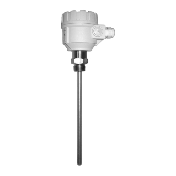
N IV O C A P
C -2 0 0 , C -2 0 0 E x, C -3 0 0
tw o-w ire com pa ct ca pa cita nce
level tra nsm itter
INSTALLATION AND PROGRAMMING MANUAL
1
Edition
st
HiTECH/NIVELCO Co.
301 Oxford Valley Road, Bldg 505 Yardley, PA 19067-7711
Phone.: (215) 321-6012 ♦ Fax: (215) 321-6067
e-mail:sales@nivelco.com ♦ www.nivelco.com
TÛV-A 03 ATEX 0019X ♦ cbr2052a0600p_01 ♦ 36/1
Advertisement
Table of Contents

Summary of Contents for Hitech Nivelco Nivocap C-200
- Page 1 INSTALLATION AND PROGRAMMING MANUAL Edition HiTECH/NIVELCO Co. 301 Oxford Valley Road, Bldg 505 Yardley, PA 19067-7711 Phone.: (215) 321-6012 ♦ Fax: (215) 321-6067 e-mail:sales@nivelco.com ♦ www.nivelco.com...
- Page 2 2/36 ♦ TÜV-A 03 ATEX 0019X ♦ cbr2052a0600p_01...
-
Page 3: Table Of Contents
C O N T E N T S 1.INTRODUCTION................5 6.PARAMETERS – DEFINITIONS AND PROGRAMMING... 23 6.1. M ........... 23 EASUREMENT CONFIGURATION 2.ORDER CODE................6 6.2. C ..............27 URRENT OUTPUT 6.3. M ........... 28 EASUREMENT OPTIMALISATION 3.TECHNICAL DATA................7 6.4. V ............29 OLUME MEASUREMENT 6.5. - Page 4 CAPACITANCE LEVEL MEASUREMENT 4/36 ♦ TÜV-A 03 ATEX 0019X ♦ cbr2052a0600p_01...
-
Page 5: Introduction
Thank you for choosing a NIVELCO instrument We are sure that you will be satisfied throughout its use 1. INTRODUCTION NIVOCAP CT-200 is a two-wire capacitance level transmitter for measuring level and volume (weight) of conductive or not-conductive liquids or free flowing solids. -
Page 6: Order Code
2. ORDER CODE NIVOCAP Not all combinations possible! NCLOSURE NTRUSION LENGTH UNCTION ROBE UTPUT MATERIAL Transmitter Rod / insulated 1” BSP Aluminium 4 ... 20 mA / standard Transmitter + display Rod / uninsulated 1” BSP Plastic 1 m 0,1m 4 ... -
Page 7: Technical Data
3. TECHNICAL DATA Rod probe Light cable probe Heavy cable probe Range 0.2 ... 3 m 1 ... 20 m Process connection St.St. DIN 1.4571 Material of wetted Fully or partially PFA coated St. St. parts Probe Fully or partially FEP coated St. St. cable PE coated steel cable (DIN 1.4301) Enclosure material... -
Page 8: Additional Data Fore
TEMPERATURE DIAGRAM PRESSURE DIAGRAM +70 T am bient +70 T am bient +130 +200 STANDARD PROBE HIGH TEMPERATURE PROBE 3.1. A DDITIONAL DATA FOR X MODELS Ex marking II 1/2G EEx ia IIB T6 Ci • 30 nF, Li • 100 µ H, Ui • 30 V, Ii • 80 m A , Pi • 0,8 W Intrinsical safe data Power supply Uo <... -
Page 9: Dimensions
3.4. D IMENSIONS IGH TEMPERATURE OD PROBE IGHT CABLE PROBE EAVY CABLE PROBE OD PROBE CT ο ο -2, 3 ο ο ο ο - ο ο CT ο ο -2, 3 ο ο ο ο - ο ο CT ο ο -2, 3 ο ο ο ο - ο ο CH ο... -
Page 10: Accessories
HART ISPLAY MODULE MODEM EFERENCE PROBE SAP-202 SAT-303 C ο ο F-1 ο ο ο ο -0 °F sec m in ho ur day C O M VAL ID 3.5. A CCESSORIES • Warranty • User’s Manual • Declaration of conformity •... -
Page 11: Installation
4. INSTALLATION 4.1. M OUNTING AND WIRING The probe has to be installed vertically and for non-conductive materials reference probe should be used. The NIVOCAP probes are mounted by 1" or 1 " process connections using S = 41 or S = 55 open end wrench, respectively. It is recommended to fix the bottom end of the cable probes. -
Page 12: Checking Of The Loop Current
EMPERATURE Electronics of the unit should be protected with shelter against development of too high temperature by direct sunshine. P rog ram m in g keys keys IRING I- I+ • Power must be switched off before wiring the unit. •... -
Page 13: Programming
5. PROGRAMMING Since NIVOCAP is not measuring level directly, the basic element of the programming is measurement (learning) at two different levels during which the instrument is learning conditions of the actual application (shape of the tank, medium to be measured, etc.). To reach accuracy given in the table of the Technical Data these two levels should be possibly near to both end of the (rod or cable) probes (See Operation and Programming of NIVOCAP on page 4) Learning will be represented (with Programming Without Display Module 5.1 and with QUICKSET) by the adjustment of 4 and 20 mA better to say assignment of 0% and 100% to these two output values respectively. -
Page 14: Programming Without Display Module
5.1. P ROGRAMMING WITHOUT DISPLAY MODULE ROGRAMMING FEATURES • 4 mA output current (direct) assignment to the minimum (0%) level • 20 mA output current (direct) assignment to the maximum (100%) level • 4 mA output current (indirect) assignment to the minimum (0%) level by means of an intermediate level •... - Page 15 Indirect assignment of the minimum and maximum level to the output current with partially filled tank For this programming the output current is to be measured on the test points as described in 4.2. Should higher accuracy be needed the current meter should be inserted in the 4 …...
- Page 16 Selecting “Fault indication” by the current output As a result of the programming current output will be 3,8 mA; 22 mA. LED S ROGRAMMING STEPS TATE FTER ROGRAMMING STEPS 1) Press key and keep it pressed NIVOCAP in programming mode 2) Press additionally key , or - 3.8 mA...
-
Page 17: Programming With The Sap-202 Display Module
5.2. P SAP-202 ROGRAMMING WITH THE DISPLAY MODULE The NIVOCAP should be adjusted to the process by programming the parameters. The SAP-200 Display Module can be used to display the parameters while programming and measurement values during measurement. The SAP-200 supports two separately accessible programming modes as below. QUICKSET (See 5.2.4) This feature is for quick programming of the 4 basic parameters like with programming without display module but aided by images on the display. -
Page 18: Steps Of The Programming
5.2.2 TEPS OF THE PROGRAMMING Programming will be performed by pressing and releasing the relevant one or two keys (simultaneously). Find a short overview of the programming while detailed descriptions are under 5.2.4 and 5.2.5. Single key pressing Selection of address and step to the value of the parameter Selection of the parameter value and step back to the address Parameter address (P01, To move the blinking of the digit to the left... -
Page 19: Indications Of The Sap-202 Programming Module And The Leds
5.2.3 SAP-202 P NDICATIONS OF THE ROGRAMMING ODULE AND THE LED indication • ECHO-LED lit in case of valid echo. °F sec min hou r day • COM-LED see description of HART SAP-202 indications The following process values can be displayed •... -
Page 20: Quickset
5.2.4 QUICKSET Suggested for simple applications Quick programming of the 4 basic parameters (like with programming without display module but) aided by images on the display. Measured values can only be displayed in percentage. QUICKSET can only be used in (%)(DEFAULT) mode (See P01 in Full Parameter Programming 5.2.5). Keys Function Enter/Quit QUICKSET programming mode... - Page 21 Screen Actions Assignment of 20 mA to the maximum level , % Fill the tank to the level required. After entering the Quickset programming mode the learning function can be started with the double key pressing . During learning the image „Store” then 100% is displayed. The parameter value represents degree in %.
-
Page 22: Full Parameter Programming
5.2.5 ULL PARAMETER PROGRAMMING Full Parameter Access is the highest programming level to access all features provided by the NIVOCAP, level, volume and weight can also be displayed in engineering units. Description of the parameters can be found under 6. paragraph. Keys Function (at least for 3 sec) -
Page 23: Parameters - Definitions And Programming
6. PARAMETERS – DEFINITIONS AND PROGRAMMING 6.1. M EASUREMENT CONFIGURATION P00: - c b a Engineering Unit System Factory default will be reloaded in the corresponding engineering units by programming this parameter. Therefore all parameters have to be set again. Operating mode Always 0 Attention: mind the sequence! - Page 24 P01: - - - a Measurement mode Parameter value „a” will determine the basic measurement value that will be displayed and proportional with the current output. Depending on the value of “a” process values as listed in the 3d column can also be displayed by pressing NEXT .
- Page 25 P03: - - - a Displayed values – Rounding Volume (VOL) display Value displayed Display arrangement Decimal position will be shifted with increasing value displayed. (See table at the left). 0,000 – 9,999 x,xxx Values over one million will be displayed in exponential format whereas the 10,000 –...
- Page 26 P05: Lower (learning) level of the operating range Programming this parameter 0% of level will be assigned to the capacitance measured in the actual application i.e. the unit will “learn” conditions of the application Programming can be started by double key pressing of .
-
Page 27: Urrent Output
6.2. C URRENT OUTPUT If in P01 a=0, this programming step is irrelevant. If level, level percentage, volume or volume percentage should be measured (a • 0 in P01) as well as first and last data pair of the linearisation table have been entered then in the procedure of the data handling the minimum and maximum values (level or volume) are in engineering units available. -
Page 28: Easurement Optimalisation
6.3. M EASUREMENT OPTIMALISATION P20: - - - a Damping This parameter can be used to reduce unwanted fluctuation of the display and output. Damping (sec) Remark No damping Applicable Recommended Recommended Recommended Recommended Applicable Applicable DEFAULT: 10 sec P32: Density of the medium (kg/dm or lb/ft in accordance with setting of (c) in P00) -
Page 29: Olume Measurement
6.4. V OLUME MEASUREMENT P40: - - ba Tank shape Tank shape Parameters programmed Standing cylindrical tank domed shape bottom Attention! P40(b), P41 (value of “b” as below) The value „a” determining the Standing cylindrical tank with conical bottom P41, P43, P44 shape of the tank should be Standing rectangular tank (with chute) P41, P42, P43, P44, P45... - Page 30 4, Activate linearisation (P47: --0) 7, Perform programming of P10 and P11. P47: - - - a Linearisation active/disabled Linearisation disabled active P48: Linearisation table Linearisation table is represented by 32 point data pairs containing capacitance in the left column (indicated by “L” -on the display) and LEVEL, VOLUME or WEIGHT in the right column (indicated by “r”...
-
Page 31: Ervice Parameters ( Read Only )
Table should always contain data L(i) = 100% Should the linearisation table contain less than 32 data pairs (j < 32) so the left column of the table must be closed wit 0: L(j < 32) = 0. The NIVOCAP will ignore data after recognising level value”0” with the serial number other than “1”.0 If the above conditions are not fulfilled error will be indicated (see Chapter Error Codes) 6.6. -
Page 32: Imulation
6.8. S IMULATION This function enables the user to test the settings of the outputs. The NIVOCAP can simulate the static or continuous change of level according to the simulation cycle time, high level and low level set in P85, P86 and P87. (The simulation levels must be within the programmed measuring range set in P04 and P05.) After selecting simulation type in P84 and setting simulation values Measurement Mode has to be re-entered. -
Page 33: Error Codes
7. ERROR CODES LED-B RROR VERWRITING LINKING URRENT RROR DESCRIPTION HAT TO DO CODE INDICATION OUTPUT Memory failure Contact service Continuous 22 mA Capacitance to be measured is too high or Check adjustment and installation conditions. damaged probe insulation Check the probe. Programmed (Level over the upper limit) Repeat programming (teaching)! - Page 34 LED-B RROR VERWRITING LINKING URRENT RROR DESCRIPTION HAT TO DO CODE INDICATION OUTPUT Hardware failure Contact service Continuous 22 mA (Analogue card failure) Check adjustment and installation conditions. Range adjustment failure 22 mA Repeat programming (teaching)! Level changes (Capacitance to be measured is outside of the range available.) during teaching may also cause this error Continuous,...
-
Page 35: Summary Of The Parameters
8. SUMMARY OF THE PARAMETERS Page Titel Value Page Titel Value d c b a d c b a Engineering unit system – Measurement mode – Engineering units – Rounding – – Density of the medium Lower (learning) level – Higher (learning) level –... - Page 36 Page Titel Value Page Titel Value d c b a d c b a – – – – Current (generator) output test – – Overall operating hours – Time elapsed after last switch- on – – Simulation mode – Simulation cycle time –...
Need help?
Do you have a question about the Nivelco Nivocap C-200 and is the answer not in the manual?
Questions and answers