Table of Contents
Advertisement
Advertisement
Table of Contents

Summary of Contents for Marksa CSSW 50
- Page 1 TECHNICAL NOTICE V1.0 NDUSTRIAL REFRIGERATION UNITS...
- Page 2 (photocopy, photography, magnetic supports or other re- cording processes), without the written authorization of Marksa SA. All rights and particularly reproduction, transla- tion, edition, distribution and also industrial property and recording are reserved.
-
Page 3: Table Of Contents
Table of contents Introduction ........................9 Foreword............................9 Typographical conventions ......................10 1.1.1 Description ........................10 1.1.2 Command......................... 10 1.1.3 Procedure......................... 10 1.1.4 Procedure result ....................... 10 1.1.5 Cross reference........................ 11 1.1.6 List of items ........................11 1.1.7 Troubleshooting........................ 11 1.1.8 Warning .......................... - Page 4 Table of contents Model CSW 200/300 ..................... 33 Description............................33 5.1.1 Overall view ........................33 5.1.2 Technical specifications....................34 Handling............................36 Installation............................36 5.3.1 Hydraulic connections ...................... 36 5.3.2 Electrical connections....................... 36 5.3.3 Filling the reservoir ......................36 Commissioning ..........................37 Specific tuning ..........................
- Page 5 Table of contents Model CSW 2000/2400 ....................57 Description............................57 9.1.1 Overall view........................57 9.1.2 Technical specifications ....................59 Handling ............................61 Installation ............................61 9.3.1 Hydraulic connections ...................... 61 9.3.2 Electrical connections....................... 61 9.3.3 Filling the reservoir ......................61 Commissioning ..........................
- Page 6 Table of contents 12 Options.......................... 73 12.1 List of the options..........................73 12.2 Air filter (A)............................75 12.2.1 Description of the option....................75 12.2.2 Maintenance ........................75 12.2.3 Breakdowns........................75 12.3 By-pass (J)............................76 12.3.1 Description of the option....................76 12.3.2 Maintenance ........................
- Page 7 Table of contents 12.15.1 Description of the option....................87 12.15.2 Maintenance........................87 12.15.3 Breakdowns........................88 12.16 Timer (T) ............................88 12.16.1 Description of the option....................88 12.16.2 Maintenance........................88 12.16.3 Breakdowns........................88 12.17 Electric valve and solenoid (W) ....................... 88 12.17.1 Description of the option....................
- Page 8 Table of contents Page 8 / 100 Technical Notice V1.0 / 01.09...
-
Page 9: Introduction 1
Foreword This manual is intended for all users of a Marksa refrigeration unit. It contains all the information ne- cessary for installation, commissioning, periodic maintenance and repair. This manual was compiled by the Marksa SA company with the same care as your refrigeration unit and is therefore an inseparable component. -
Page 10: Typographical Conventions
1 Introduction Typographical conventions The following styles are used in this manual. 1.1.1 Description This style, use in conjunction with illustration numbers, is preceded with the corresponding numbers: Example: First element Second element Etc... 1.1.2 Command Any software command, button, function key, window, icon, option, tab, checkbox, selection box, article, menu, tool bar, field and section used in this document is represented by a bold italic font. -
Page 11: Cross Reference
Introduction 1 1.1.5 Cross reference This style is used to helps the user find complementary information linked to the current subject. Example: See section “4.2.4 Sensor Board Positioning” on page 47. 1.1.6 List of items This style is used in order to display a list of elements. Example: •... -
Page 12: Warning
Example The use of other cleaning agents or hard objects may damage the ID-Pipetor EP-5. Do not use others cleaning agents or products prior to consult Marksa SA and to receive the agreement. 1.1.9 Recommendation and Note When additional information is necessary and its non-respect conduct to minor inconveniences, recom- mendations and notes are presented. - Page 13 Introduction 1 Example For more information, contact either your DiaMed AG representative or the manufacturer direct- 1.1.9.2 Note Used to give a general or purely informative remark. Example The housing reassembly must follow the reverse order of the disassembly. Technical Notice V1.0 / 01.09 Page 13 / 100...
- Page 14 1 Introduction Page 14 / 100 Technical Notice V1.0 / 01.09...
-
Page 15: Generalities 2
Generalities 2 Chapter contents This chapter contains generic information applicable to all refrigeration unit models. In particular, it contains instructions concerning safety as well as practical and theoretical information. Appropriate usage The refrigeration unit is intended to be used to maintain the ambient temperature of a machine tool. It can be only be used by trained and authorised personnel. -
Page 16: Graphic Symbols
2 Generalities 2.2.3 Graphic symbols The following symbols may be present on your refrigeration unit: Symbol Description Risk of electrocution Risk of burns Table 2-1: Symbols Page 16 / 100 Technical Notice V1.0 / 01.09... -
Page 17: Operation
Generalities 2 Operation 2.3.1 Basic schematic 2.3.1.1 Direct cooling of the tank BP - HP (10) (11) (12) (13) (14) Fig. 2-1 : Basic schematic Technical Notice V1.0 / 01.09 Page 17 / 100... -
Page 18: Principles Of Operation
2 Generalities 2.3.1.2 Legend Pump Temperature probe Thermostat Compressor Safety pressure controller (an option on the CSW100) Exhaust fan Condenser Temperate water inlet Cold water outlet (10) Reservoir (11) Evaporator (12) Pressure regulator (13) Dehumidifier (14) Cooling circuit 2.3.2 Principles of operation The whole range of water chillers supply chilled water (9) continuously at a constant temperature. -
Page 19: Separated Tank And Refrigeration Units
Generalities 2 2.3.3 Separated tank and refrigeration units For refrigeration units of greater capacity, the refrigerant liquid returned is stored in a reservoir (10) then pumped (1) and chilled (11) before being returned back to the cooling circuit (8).. (10) (11) (12) (13) -
Page 20: Models And Available Options
2 Generalities Models and available options The CSW range of industrial water chillers covers several models, classified according to their capacities and available options. The following models are currently available: Refrigerant Refrigerant Model Capacity Model Capacity CSW 50 0.5 kW 134A CSW 800 7.8 kW... -
Page 21: Model Csw 50/65/80 3
Model CSW 50/65/80 3 Chapter contents This chapter contains information specific to the CSW 50, CSW 65 and CSW 80 models. It covers all topics associated with installation, commissioning, tuning and maintenance of these models. For reasons of clarity, only the CSW 80 model is described in the current chapter. However, all of the explanations apply in a similar fashion to the CSW 50 and CSW 65 models. - Page 22 3 Model CSW 50/65/80 Fig. 3-2 : CSW 80 type chiller (rear view) Cooling liquid outlet Cooling liquid return inlet Refilling port Visual water-level indicator Electric power connector Page 22 / 100 Technical Notice V1.0 / 01.09...
-
Page 23: Technical Specifications
Model CSW 50/65/80 3 3.1.2 Technical specifications 3.1.2.1 Standard operating parameters Description Units CSW 50 CSW 65/80 Refrigerant Type R134A R134A Refrigerating capacity Power consumption 0.23 0.41 Heat load 0.75 Inlet temperature °C Outlet temperature °C Flow rate l/min Maximum input temperature °C 3.1.2.2 Electrical data Description... - Page 24 3 Model CSW 50/65/80 Hydraulic circuit Description Units CSW 50 CSW 65/80 Flow rate l/min Total pressure Power input 0.16 0.16 Amperage 0.70 0.70 Rotation t/min 2900 2900 Power supply V x ph x Hz 230 x 1 x 50 230 x 1 x 50 Stainless steel reservoir Inlet/outlet couplings...
-
Page 25: Handling
Prepare a mixture of water and 30% ethylene gly- col. Do not use anti-freeze intended for motor vehi- cles. Marksa recommends ANTIFROGEN N antifree- Unscrew the cap (1). Fig. 3-3 : Filler cap Fill the reservoir to somewhere between the mini- mum and maximum levels of the indicator (2). -
Page 26: Commissioning
3 Model CSW 50/65/80 Commissioning The unit has been checked, tuned and tested in our workshops. Make the hydraulic and electrical connections. Fill the reservoir with liquid. Start up the machine (1). Check the rotation direction of the pump and the exhaust fan. -
Page 27: Model Csw 100/150 4
Model CSW 100/150 4 Chapter contents This chapter contains information specific to the CSW 100 and CSW 150 models. It covers all topics as- sociated with installation, commissioning, tuning and maintenance of these models. For reasons of clarity, only the CSW 100 model is described in the current chapter. However, all of the explanations apply in a similar fashion to the CSW 150 model. -
Page 28: Technical Specifications
4 Model CSW 100/150 4.1.2 Technical specifications 4.1.2.1 Standard operating parameters Description Units CSW 100 CSW 150 Refrigerant Type R134A R134A Refrigerating capacity 1.20 1.50 Power consumption 0.53 0.53 Heat load 1.73 1.73 Inlet temperature °C Outlet temperature °C Flow rate l/min Maximum input temperature °C... - Page 29 Model CSW 100/150 4 Hydraulic circuit Description Units CSW 100 CSW 150 Flow rate l/min Total pressure Power input 0.16 0.16 Amperage 0.70 0.70 Rotation t/min 2900 2900 Power supply V x ph x Hz 230 x 1 x 50 230 x 1 x 50 Stainless steel reservoir Inlet/outlet couplings...
-
Page 30: Handling
Prepare a mixture of water and 30% ethylene gly- col. Do not use anti-freeze intended for motor vehi- cles. Marksa recommends ANTIFROGEN N antifree- Unscrew the cap (1). Fig. 4-2 : Filler cap Fill the reservoir to somewhere between the mini- mum and maximum levels of the indicator (2). -
Page 31: Commissioning
Model CSW 100/150 4 Commissioning The unit has been checked, tuned and tested in our workshops. Make the hydraulic and electrical connections. Fill the reservoir with liquid. Start up the machine (1). Check the rotation direction of the pump and the exhaust fan. - Page 32 4 Model CSW 100/150 Page 32 / 100 Technical Notice V1.0 / 01.09...
-
Page 33: Model Csw 200/300 5
Model CSW 200/300 5 Chapter contents This chapter contains information specific to the CSW 200 and CSW 300 models. It covers all topics as- sociated with installation, commissioning, tuning and maintenance of these models. For reasons of clarity, only the CSW 200 model is described in the current chapter. However, all of the explanations apply in a similar fashion to the CSW 300 model. -
Page 34: Technical Specifications
5 Model CSW 200/300 5.1.2 Technical specifications 5.1.2.1 Standard operating parameters Description Units CSW 200/300 CSW200E/300E Refrigerant Type R134A R134A Refrigerating capacity 3000 3000 Power consumption 1355 1355 Heat load 4355 4355 Inlet temperature °C Outlet temperature °C Flow rate l/min Maximum input temperature °C... - Page 35 Model CSW 200/300 5 Hydraulic circui Description Units CSW 200/300 CSW200E/300E Flow rate l/min Total pressure 0.40 0.50 Power input 0.16 0.25 Amperage 0.70 0.80 Rotation t/min 2900 2900 Power supply V x ph x Hz 230 x 1 x 50 400 x 3 x 50 Stainless steel reservoir Dimensions...
-
Page 36: Handling
Prepare a mixture of water and 30% ethylene gly- col. Do not use anti-freeze intended for motor vehi- cles. Marksa recommends ANTIFROGEN N antifree- Unscrew the cap (1). Fig. 5-2 : Filler cap Fill the reservoir to somewhere between the mini- mum and maximum levels of the indicator (2). -
Page 37: Commissioning
Model CSW 200/300 5 Commissioning The unit has been checked, tuned and tested in our workshops. Make the hydraulic and electrical connections. Fill the reservoir with liquid. Start up the machine (1). Check the rotation direction of the pump and the exhaust fan. - Page 38 5 Model CSW 200/300 Page 38 / 100 Technical Notice V1.0 / 01.09...
-
Page 39: Model Csw 400 6
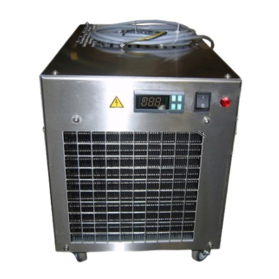
Model CSW 400 6 Chapter contents This chapter contains information specific to the CSW 400 model. It covers all topics associated with ins- tallation, commissioning, tuning and maintenance of these models. Description 6.1.1 Overall view Abb. 6-1 : CSW 400 type chiller Programmable controller display (optional) Thermostat display Breakdown indicator lamp (red) -
Page 40: Technical Specifications
6 Model CSW 400 6.1.2 Technical specifications 6.1.2.1 Standard operating parameters Description Units CSW 400 Refrigerant R134A Refrigerating capacity 4000 Power consumption 1200 Heat load 5200 Inlet temperature °C Outlet temperature °C Flow rate l/min Maximum input temperature °C 6.1.2.2 Electrical data Description Units CSW 400... - Page 41 Model CSW 400 6 Hydraulic circui Description Units CSW 400 Flow rate l/min Total pressure Power input 0.37 Amperage 1.80 Rotation t/min 2900 Power supply V x ph x Hz 400 x 3 x 50 Stainless steel reservoir Inlet/outlet couplings 3/4’’...
-
Page 42: Handling
Prepare a mixture of water and 30% ethylene gly- col. Do not use anti-freeze intended for motor vehi- cles. Marksa recommends ANTIFROGEN N antifree- Unscrew the cap (1). Abb. 6-2 : Filler cap Fill the reservoir to somewhere between the mini- mum and maximum levels of the indicator (2). -
Page 43: Commissioning
Model CSW 400 6 Commissioning The unit has been checked, tuned and tested in our workshops. Make the hydraulic and electrical connections. Fill the reservoir with liquid. Start up the machine (1). Check the rotation direction of the pump and the exhaust fan. - Page 44 6 Model CSW 400 Seite 44 / 100 Technical Notice V1.0 / 01.09...
-
Page 45: Model Csw 600/800 11
Model CSW 600/800 11 Chapter contents This chapter contains information specific to the CSW 600 and CSW 800 models. It covers all topics as- sociated with installation, commissioning, tuning and maintenance of these models. For reasons of clarity, only the CSW 800 model is described in the current chapter. However, all of the explanations apply in a similar fashion to the CSW 600 model. - Page 46 11 Model CSW 600/800 (11) (10) Fig. 11-2 : CSW 800 type chiller (rear view) Output circuit pressure gauge (on request) Electric power connector (on request) Cooling liquid return inlet Cooling liquid outlet Refilling port (10) Drainage tap (11) Visual water-level indicator Page 70 / 100 Technical Notice V1.0 / 01.09...
-
Page 47: Technical Specifications
Model CSW 600/800 11 11.1.2 Technical specifications 11.1.2.1 Standard operating parameters Description Units CSW 600/800 Refrigerant Type R407C Refrigerating capacity 7900 Power consumption 1500 Heat load 7500 Inlet temperature °C Outlet temperature °C Flow rate l/min Maximum input temperature °C Table 11-1: 11.1.2.2 Electrical data Description... - Page 48 11 Model CSW 600/800 Description Units CSW 600/800 Flow rate l/min Charge loss Table 11-4: Hydraulic circui Description Units CSW 600/800 Flow rate l/min Total pressure Power input 0,37 Amperage Rotation t/min 2900 Power supply V x ph x Hz 400 x 3 x50 Stainless steel reservoir Inlet/outlet couplings...
-
Page 49: Handling
Prepare a mixture of water and 30% ethylene gly- col. Do not use anti-freeze intended for motor vehi- cles. Marksa recommends ANTIFROGEN N antifree- Unscrew the cap (1). Fig. 11-3 : Filler cap Fill the reservoir to somewhere between the mini- mum and maximum levels of the indicator (2). -
Page 50: Commissioning
11 Model CSW 600/800 11.4 Commissioning The unit has been checked, tuned and tested in our workshops. Make the hydraulic and electrical connections. Fill the reservoir with liquid. Start up the machine (1). Check the rotation direction of the pump and the exhaust fan. -
Page 51: Model Csw 900/1000/1300/1700 11
Model CSW 900/1000/1300/1700 11 Chapter contents This chapter contains information specific to the CSW 900, CSW 1000, CSW 1300 et CSW 1700models. It covers all topics associated with installation, commissioning, tuning and maintenance of these models. For reasons of clarity, only the CSW 1000 model is described in the current chapter. However, all of the explanations apply in a similar fashion to the CSW 900, CSW 1300 et CSW 1700 models. - Page 52 11 Model CSW 900/1000/1300/1700 Fig. 11-2 : CSW 1000 type chiller (rear view) Electric power connector Cooling liquid return inlet Cooling liquid outlet Visual water-level indicator Drainage tap Page 70 / 100 Technical Notice V1.0 / 01.09...
-
Page 53: Technical Specifications
Model CSW 900/1000/1300/1700 11 11.1.2 Technical specifications 11.1.2.1 Standard operating parameters Description Units CSW 900/1000 CSW 1300 CSW 1700 Refrigerant Type R407C R407C R407C Refrigerating capacity 16,4 Power consumption Heat load 11,9 15,5 20.9 Inlet temperature °C Outlet temperature °C Flow rate l/min Maximum input temper-... - Page 54 11 Model CSW 900/1000/1300/1700 Evaporator Description Units CSW 900/1000 CSW 1300 CSW 1700 Composition AISI 316 AISI 316 AISI 316 Flow rate l/min Charge loss 0,25 0,25 Table 11-4: Hydraulic circui Description Units CSW 900/1000 CSW 1300 CSW 1700 Flow rate l/min Total pressure Power input...
-
Page 55: Handling
Prepare a mixture of water and 30% ethylene gly- col. Do not use anti-freeze intended for motor vehi- cles. Marksa recommends ANTIFROGEN N antifree- Fig. 11-3 : Filler cap Unscrew the cap (1). Fill the reservoir to somewhere between the mini- mum and maximum levels of the indicator (2). -
Page 56: Commissioning
11 Model CSW 900/1000/1300/1700 11.4 Commissioning The unit has been checked, tuned and tested in our workshops. Make the hydraulic and electrical connections. Fill the reservoir with liquid. Start up the machine (1). Check the rotation direction of the pump and the exhaust fan. -
Page 57: Model Csw 2000/2400 11
Model CSW 2000/2400 11 Chapter contents This chapter contains information specific to the CSW 2000 and CSW 2400 models. It covers all topics associated with installation, commissioning, tuning and maintenance of these models. For reasons of clarity, only the CSW 2000 model is described in the current chapter. However, all of the explanations apply in a similar fashion to the CSW 2400 model. - Page 58 11 Model CSW 2000/2400 Fig. 11-2 : CSW 2000 type chiller (rear view) Electric power connector (optional) Output circuit pressure gauge Cooling liquid outlet Cooling liquid return inlet Drainage tap Page 70 / 100 Technical Notice V1.0 / 01.09...
-
Page 59: Technical Specifications
Model CSW 2000/2400 11 11.1.2 Technical specifications 11.1.2.1 Standard operating parameters Description Units CSW 2000 CSW 2400 Refrigerant Type R407C R407C Refrigerating capacity 20,0 24,0 Power consumption Heat load 26,7 31,4 Inlet temperature °C Outlet temperature °C Flow rate l/min Maximum input temperature °C 11.1.2.2 Electrical data... - Page 60 11 Model CSW 2000/2400 Hydraulic circui Description Units CSW 2000 CSW 2400 Flow rate l/min Total pressure Power input 0,37 0,37 Amperage Rotation t/min 2900 2900 Power supply V x ph x Hz 400 x 3 x 50 400 x 3 x 50 Stainless steel reservoir Inlet/outlet couplings 1’’...
-
Page 61: Handling
Prepare a mixture of water and 30% ethylene gly- col. Do not use anti-freeze intended for motor vehi- cles. Marksa recommends ANTIFROGEN N antifree- Unscrew the cap (1). Fig. 11-3 : Filler cap Fill the reservoir to somewhere between the mini- mum and maximum levels of the indicator (2). -
Page 62: Commissioning
11 Model CSW 2000/2400 11.4 Commissioning The unit has been checked, tuned and tested in our workshops. Make the hydraulic and electrical connections. Fill the reservoir with liquid. Start up the machine (1). Check the rotation direction of the pump and the exhaust fan. -
Page 63: Model Csw 3000/3500/4700 11
Model CSW 3000/3500/4700 11 Chapter contents This chapter contains information specific to the CSW 3000, CSW 3500 and CSW 4700 models. It co- vers all topics associated with installation, commissioning, tuning and maintenance of these models. For reasons of clarity, only the CSW 3000 model is described in the current chapter. However, all of the explanations apply in a similar fashion to the CSW 3500 and CSW 4700 models. - Page 64 11 Model CSW 3000/3500/4700 Fig. 11-2 : CSW 3000 type chiller (rear view) Cooling liquid outlet Cooling liquid return inlet Page 70 / 100 Technical Notice V1.0 / 01.09...
-
Page 65: Technical Specifications
Model CSW 3000/3500/4700 11 11.1.2 Technical specifications 11.1.2.1 Standard operating parameters Description Units CSW 3000 CSW 3500 CSW 4700 Refrigerant Type R407C R407C R407C Refrigerating capacity 30,0 35,0 47,0 Power consumption 10,7 9,55 Heat load 38,4 45,7 56,55 Inlet temperature °C Outlet temperature °C... - Page 66 11 Model CSW 3000/3500/4700 Hydraulic circui Description Units CSW 3000 CSW 3500 CSW 4700 Flow rate l/min Total pressure Power input 0,55 0,55 Amperage Rotation t/min 2800 2800 2900 Power supply V x ph x Hz 400 x 3 x 50 400 x 3 x 50 400 x 3 x 50 Stainless steel reservoir...
-
Page 67: Handling
Prepare a mixture of water and 30% ethylene gly- col. Do not use anti-freeze intended for motor vehi- cles. Marksa recommends ANTIFROGEN N antifree- Unscrew the cap (1). Fig. 11-3 : Filler cap Fill the reservoir to somewhere between the mini- mum and maximum levels of the indicator (2). -
Page 68: Commissioning
11 Model CSW 3000/3500/4700 11.4 Commissioning The unit has been checked, tuned and tested in our workshops. Make the hydraulic and electrical connections. Fill the reservoir with liquid. Start up the machine (1). Check the rotation direction of the pump and the exhaust fan. -
Page 69: Tuning And Maintenance 11
Tuning and maintenance 11 Chapter contents This chapter describes the various possible control settings and the common maintenance operations for the entire range of CSW chillers. 11.1 Control settings 11.1.1 Thermostat For machines equipped with the hot gas by- pass option, the thermostat operation is diffe- mute rent. - Page 70 The only parameter that the user is authorised to change is the differential regulator. The modi- fication of any other parameter may affect the operation of the refrigeration unit in an inappro- priate manner. Marksa SA denies all responsibility for any un-authorised parameter modification. Page 70 / 100 Technical Notice V1.0 / 01.09...
-
Page 71: Maintenance
Tuning and maintenance 11 11.2 Maintenance 11.2.1 Periodic maintenance Regular maintenance by competent personnel makes it possible to ensure reliable and efficient opera- tion of the refrigeration unit. 11.2.2 Safety LECTROCUTION ET BLESSURES GRAVES Always disconnect the power supply of the unit before any maintenance operation. There is a significant risk of burns from contact with the copper piping. -
Page 72: Annual Maintenance
11 Tuning and maintenance 11.2.6 Annual maintenance Cut the power supply on the outside of the machine. Check the exhaust fan motor bearings. If need be, replace the bearings. Clean the exhaust fan blades. Start with a visual inspection of all of the components (cabling and capillaries included) in order to be sure that noen of the components are either broken, damaged, ice-encrusted or fouled (exhaust fan, condenser). -
Page 73: Options 12
Options 12 Chapter contents This chapter describes the various options and their availability depending on the refrigeration unit mo- dels. 12.1 List of the options Legend: Option X Standard 900 - 3000 - 2000 Abb. Option 50-65 600 & 1000 - 3500 &... - Page 74 12 Options 900 - 3000 - 2000 Abb. Option 50-65 600 & 1000 - 3500 & & 80 & 150 & 300 1300 - & 2400 1700 4700 Electric valve solenoid Programma- ble problem recovery controller High tempera- ture alarm Table 12-1: List of the options Page 74 / 100 Technical Notice V1.0 / 01.09...
-
Page 75: Air Filter (A)
Options 12 12.2 Air filter (A) 12.2.1 Description of the option Fig. 12-1 : Air filter (metallic) Air filters make it possible to protect the condenser against impurities in the air. The filters can be either metallic or synthetic. 12.2.2 Maintenance 12.2.2.1 Metallic filters Metallic filters should be cleaned monthly during the regular monthly maintenance procedure. -
Page 76: By-Pass (J)
12 Options 12.3 By-pass (J) 12.3.1 Description of the option BP - HP Fig. 12-2 : Basic schematic In the event of excessive pressure in the outlet port of the refrigeration unit, the bypass is engaged and reinjects the liquid into the reservoir in order to avoid damages in the external circuit. 12.3.2 Maintenance The bypass is regulated in the factory. -
Page 77: Distributor (D)
Options 12 12.4 Distributor (D) 12.4.1 Description of the option The distributor makes it possible to split the refrigeration liquid between several circuits. 12.4.2 Maintenance No special maintenance procedures. 12.4.3 Breakdowns No special breakdown procedures. 12.5 400V power supply (E) 12.5.1 Description of the option A 400V power supply makes it possible to use electrical components with very high reliability. -
Page 78: Water-Flow Controller (F)
12 Options 12.6 Water-flow controller (F) 12.6.1 Description of the option Fig. 12-3 : Basic schematic The water flow controller makes it possible to detect faults in the external refrigeration circuit (the custo- mer's machine). Its operation is to provide a delay in order to avoid the display of disruptive errors during the start-up of the refrigeration unit. -
Page 79: Hot Gas Bypass (G)
Options 12 12.7 Hot gas bypass (G) 12.7.1 Description of the option BP - HP Fig. 12-4 : Basic schematic The hot gas bypass option makes it possible to precisely maintain the liquid temperature by eliminating disruptive starting up and powering down of the compressor. Precision in the order of ±... -
Page 80: Thermostat
12 Options 12.7.2 Thermostat 12.7.2.1 Description Display n°. 1 Displays the process value or the parameter sym- bols. Display n°. 2 Displays the setting's value, the ramp setting's va- lue, the heating capacity or the selection of para- meters. Visual operation indicators OUT1 OUT1 OUT2 MANU STOP RMT... -
Page 81: Maintenance
Options 12 Parameter setting mode (SET) Ent-t Entry type ........1 Select either °C / °F....C oUt 1 Cont allocation 1......Heat oUt 2 Cont allocation 2......Al 1 Sub 1 Auxiliary outlet ......Al 2 AL t 1 Alarm 1 type ......2 AL In Alarm 1 opening ......n-C AL t 2 Alarm 2 type ......2... -
Page 82: Pre-Heating Kit (H)
12 Options 12.8 Pre-heating kit (H) 12.8.1 Description of the option BP - HP Fig. 12-7 : Schéma de principe Heating (1) makes it possible to pre-heat water that might be too cold, particularly useful when pre-hea- ting the machine or when the refrigeration unit(s) are located outside the building. A safety thermostat (2) protects the tank from inadequacies in the heating system. -
Page 83: Thermal Insulation (I)
Options 12 12.9 Thermal insulation (I) 12.9.1 Description of the option Thermal insulation of the refrigeration unit makes it possible to reduce condensation. This option is re- commended particularly for situations where the refrigeration units supply water at a temperature less than 15°C (59°F). -
Page 84: Contrôle De Niveau (N)
12 Options 12.12 Contrôle de niveau (N) 12.12.1 Description of the option Fig. 12-8 : Basic schematic A float in the reservoir makes it possible to check on the liquid levels. If the level is too low, in order to avoid any damage, the refrigeration unit stops itself and an alarm is shown on the programmable control- ler display and/or on the visual display located on the front panel. -
Page 85: Circuit D'eau Sous Pression (P)
Options 12 12.13 Circuit d’eau sous pression (P) 12.13.1 Description of the option The customer's circuit is pressurised (several bars). 12.13.2 Maintenance Maintenance and required checking are reduced. Fig. 12-9 : Basic schematic The circuit is pressurised. Eliminate the pressure before any intervention on the customer's coo- ling circuit: Open the drainage tap (1) and check the manometer until zero pressure is obtained. -
Page 86: Reinforced Pump (R)
12 Options 12.14 Reinforced pump (R) 12.14.1 Description of the option A reinforced pump makes it possible to ensure better liquid circulation during significant load losses (coo- ling of spindles, for example). 12.14.2 Maintenance No special maintenance procedures. 12.14.3 Breakdowns No special breakdown procedures. -
Page 87: Lp/Hp Safety Pressure Controllers (S)
Options 12 12.15 LP/HP safety pressure controllers (S) 12.15.1 Description of the option BP - HP Fig. 12-10 : Basic schematic The pressure controller (1) makes it possible to protect the compressor against any possible loss of gas in the refrigeration circuit (LP) and protects the compressor after any significantly excess of pressure of the refrigerant gas (HP). -
Page 88: 12.15.3 Breakdowns
12 Options 12.15.3 Breakdowns Activation of the LP section Gas leakage, insufficient gas quantities ✔ Find the origin of the leakage(s). Check and reconnect the circuit. Activation of the HP section Fouled heat exchanger ✔ Clean the heat exchanger and air filters (if fitted). Ambient temperature is too high (above the manufacturer's specified limit). -
Page 89: High Temperature Alarm (Y)
Options 12 12.18 High temperature alarm (Y) 12.18.1 Description of the option The high temperature alarm indicates an incorrect operation of the device. This information is forwarded to the device by the equipment being cooled. An error is forwarded to the device in the event of overheating. It may be caused by: A loss of gas. - Page 90 12 Options Page 90 / 100 Technical Notice V1.0 / 01.09...
-
Page 91: Breakdowns 13
Breakdowns 13 Chapter contents This chapter contains instructions useful in the event of a breakdown of your refrigeration unit. 13.1 Warnings We decline all responsibility for operations carried out on the unit by non-qualified personnel. Before intending to repair the refrigeration circuit strictly speaking, first ensure that control system is wor- king properly and is correctly configured. -
Page 92: 13 Breakdowns
13 Breakdowns 13.3 Breakdowns Before any intervention on the unit, cut off its power supply at the source. Take care of certain parts of the refrigeration circuit which can be very hot. Problems with normal operations are manifested by: • a halt of the refrigeration unit (one or more pumps and/or the compressor do not run) •... - Page 93 Breakdowns 13 The motor doesn't run Check the rotation direction. Circuit breaker activated ✔ Check the liquid level. ✔ Reset the circuit breaker. Faulty bearings ✔ Replace the bearings. Insufficient fluid ✔ Add some fluid. Non-standard fluid quality ✔ Change the fluid. Motor out of order ✔...
- Page 94 13 Breakdowns HP contact is open (optional on CSW50 through CSW150) Ambient temperature is too high ✔ Cut off the power supply Cool down the local environment Restart the unit by pressing the pressure switch RESET button Restart the power supply Filters (optional) fouled ✔...
-
Page 95: Appendix 14
Appendix 14 Chapter contents This chapter contains various information applicable to the entire range of CSW water chillers. For infor- mation specific to your model, please refer to the schematics and technical data sheets in the appendix. 14.1 Compliance 14.1.1 Directives Your refrigeration unit is compliant with directive 98/37/CE from the European Parliament and Council on June 22nd 1998 relating to the unification of the legislation of member states regarding machinery. -
Page 96: Disposal Of The Product
Appendix 14.2 Disposal of the product 14.2.1 General remarks In order to protect both people and the environment, any device and its accessories must be disposed of according to regulations. The legislation and local regulations applicable for the elimination of waste must also necessarily be respected. -
Page 97: Maintenance Sheet
Appendix 14 14.3 Maintenance sheet The original blank maintenance sheet must be kept with this manual. Whenever a maintenance intervention is required, make a copy of it and then fill out the details. Maintenance / Event / Fault Action Operator Date Technical Notice V1.0 / 01.09 Page 97 / 100... -
Page 98: Technical Data Sheet
Appendix 14.4 Technical data sheet This notice being common to several refrigeration unit models, the information specific to your model ap- pears in a separately delivered technical data file. This file contains the following elements: • Electrical schematics • Test sheets •... -
Page 99: Compliance Documents
Appendix 14 14.5 Compliance documents Technical Notice V1.0 / 01.09 Page 99 / 100... - Page 100 93/44, à la directive 73/23 ainsi qu'à la directive CEM/EMV 89/336 avec les amendements 92/31. Nous déclarons que la présente machine est conforme. DECLARATION OF CONFORMITY We, MARKSA S.A. – av. du Technicum 42 – 2400 Le Locle, declare under our sole responsibility that the machine : Fabrication : Marksa...
Need help?
Do you have a question about the CSSW 50 and is the answer not in the manual?
Questions and answers