Table of Contents
Advertisement
Advertisement
Table of Contents

Summary of Contents for Shuang Ri SR501
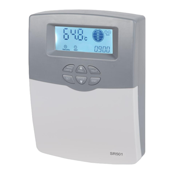
- Page 1 SR501 Please read the manual carefully before operation!
-
Page 2: Table Of Contents
SR501 EN Operation Manual Contents Safety information ..................3 1.1 Installation and commissioning ..............3 1.2 Liability waiver ....................3 1.3 Signal description ..................4 2. Installation ....................... 4 2.1 Mounting controller ..................4 2.2 Power connection ..................5 2.3 Terminal port connection ................6 2.4 Advice regarding the installation of temperature sensors ...... - Page 3 SR501 EN Operation Manual time-sections ..................... 27 6.6 AH Automatic thermostat function ............... 33 6.7 OTF Timer function ..................35 6.8 TKPR Tank high temperature protection function ........36 6.9 CFR Tank anti-freezing protection .............. 37 6.10 LWS Preset the water level of water filling when tank is lack of water ..38 6.11 LWSD delay time of water filling when tank is lack-of water .....
-
Page 4: Safety Information
SR501 EN Operation Manual 1. Safety information We have carefully checked the text and pictures of this manual and provided the best of our knowledge and ideas, however inevitable errors maybe exist. Please note that we cannot guarantee that this manual is given in the integrity of image and text, incorrect, incomplete and erroneous information and the resulting damage we do not take responsibility. -
Page 5: Signal Description
SR501 EN Operation Manual and liability for losses, damages or cost that might arise due to improper installation, operation or wrong utilization and maintenance or that occurs in some connection with the above-mentioned. Moreover, we do not take over liability for patent infringements or infringements occurring with the use of this controller on the third parties’... -
Page 6: Power Connection
SR501 EN Operation Manual This controller can only be installed in the place having an adequate level of protection. ►Choosing a suitable site ►Drilling the upper fixing hole ① ►Screwing on the screw ►Taking away the cover plate ►Hanging the bottom plate on the fixing hole ①... -
Page 7: Terminal Port Connection
SR501 EN Operation Manual ③ ③ ④ ④ 2.3 Terminal port connection Before opening the terminal, please be sure to switch-off the power and pay attention to the local electricity supply rules. Terminal layout of controller for electrical heater of 1500W •... - Page 8 With Auxiliary electrical heating, the user must install the leakage protector himself. • SR501 Remote display(optional accessory) SR501(1500W)controller is designed to be able to connect to a remote display, and on display, it is possible to set up the functions like manually water filling, manually trigger heating, manually trigger...
- Page 9 SR501 EN Operation Manual T1: for NTC10K, B=3950, ≤135 C temperature sensor (PVC cable ≤105 designed for DHW circulation TCYC or AH function (optional) T2: for NTC10K, B=3950, ≤135 C sensor (PVC cable ≤105 C), designed for pipe anti-freezing function (optional) Note: T1, T2 temperature sensors are not included in the standard parts of delivery, which should be purchased separately.
- Page 10 C sensor (PVC cable ≤105 C), designed for pipe anti-freezing function (optional) Note: SR501-3KW has no remote display function. T1, T2 temperature sensors are not included in the standard parts of delivery, which should be purchased separately. - 9 -...
-
Page 11: Advice Regarding The Installation Of Temperature Sensors
SR501 EN Operation Manual 2.4 Advice regarding the installation of temperature sensors T1, T2 sensor cables carry low voltage, and to avoid inductive effects, must not be laid close to 230 Volt or 400 Volt cables (minimum separation of 100mm). -
Page 12: Installation Of Sensor Of Temperature And Water Level
SR501 EN Operation Manual ensure no damaged during installation and no torsion effect positioned on the solenoid valve, it is not allowed to install valve compulsively when tow connectors are not aligned. Two-cores wire is used for connection with solenoid valve, if wire needs to be lengthened, please select cable of 1.0mm... -
Page 13: Bottom Installation Of Sensor Of Temperature And Water Level
SR501 EN Operation Manual b).”Top mounted sensor” (need to be specified in order) see the picture2 c).”Bottom mounted sensor” (Need to be specified in order) refer the details of Paragraph 2.7 2). To avoid the measuring error or damage the sensor, sensor of temperature and water level must not touch or close to the e-heater tube 2.7 Bottom installation of sensor of temperature and water level... -
Page 14: System Diagram
SR501 EN Operation Manual 3. System diagram Note: this diagram is only for reference 4. Functions operation Before switching-on the power, please connect sensor of temperature and water level, water filling solenoid valve to the input port of controller, connect electrical heater to the output port of controller. -
Page 15: Signals On Display And Function Code
SR501 EN Operation Manual 4.1 Signals on display and function code LCD display screen Code Description Code/Signal Lighting Code/Signal Blink Function is Function is activated Thermostat heating Constant running Temperature Countdown of OTDI Thermal disinfection disinfection function function (check under working (DDIS)... -
Page 16: Button Description
SR501 EN Operation Manual 4.2 Button description Buttons layout on the controller • Button description “Water Loading” button: water filling manually (detailed see section 7.1) “HEAT” button: heating manually (detailed see section 7.3) “SET” button: access the menu or activate the set value “ESC”... - Page 17 SR501 EN Operation Manual functions ► Press “▲▼” to adjust the main menu ► Press “SET” to access submenu • Submenu operation steps ► Press “SET” to access submenu ► Press “SET” again to the adjustable item, press “▲▼” to select “ON” to activate the option, or select “OFF”...
-
Page 18: Menu Structure
SR501 EN Operation Manual 4.3 Menu structure Controlled can be detailed set through the submenu, please understand and get familiar with the submenu. 4.4 Menu description Main functions menu (for users) Code Code Default value Description (Main menu) (Submenu) - Page 19 SR501 EN Operation Manual Auxiliary functions menu (for professionals) Code Code Default value Description (Main menu) (Submenu) Thermostat heating function Switch-on time and temperature of the 1 tH1O 00:00/55℃ time section of CTH function Switch-off time and temperature of the 1 tH1F 23:59/60℃...
- Page 20 SR501 EN Operation Manual Automatic thermostat function (output port: Sensor selection for automatic thermostat tst / S1 function (tst indicates tank temperature, S1 indicates T1 temperature sensor) Switch-on temperature 40℃ Switch-off temperature 45℃ tA1O 00:00 Switch-on time of the 1...
-
Page 21: Main Functions Setup (For Users)
SR501 EN Operation Manual automatically, and its function status displays NONE. for example: if PUMP water filling pump function is set to “on”, then if you want to trigger AH function, then you need to close the function PUMP firstly. - Page 22 SR501 EN Operation Manual the electrical heater is triggered to heat to the desired temperature. Timing filling and heating factory default reference as below: • The first time: at 3:00 a.m. to fill water to the water level of 50%, at 4:00 a.m.
- Page 23 SR501 EN Operation Manual Repeat above steps to set the time and water level of the second and the third of timing water filling (“Time Water ②” and “Time Water ③” ). ►Press “▲” button, timing heating “Time Heat ①” displays.
-
Page 24: Temperature Controlled Water Filling Function
SR501 EN Operation Manual The “Auto” icon Both of Equivalent to summer “timing filling” and disappear mode “timing heating” are deactivate 5.3 Temperature controlled water filling function Description: When this function is activated, then water filling is controlled by temperature which set by user. - Page 25 SR501 EN Operation Manual Purpose of this function is ensuring user can get enough hot water. when tank temperature is reached to the switch-on temperature, the electrical heater is triggered immediately to heat tank, and when temperature reaches to the desired temperature, electrical heater is stopped.
-
Page 26: Lwpr Low Water Pressure
SR501 EN Operation Manual time section of thermostat heating) ►Press “SET” button, hour “00” blinks ►Press “▲▼” button, to adjust hour. ►Press “SET” button, minute “00” blinks ►Press “▲▼” button, to adjust minute. ►Press “SET” button, temperature “55 C” blinks ►Press “▲▼”... -
Page 27: Cwl Constant Water Level Filling Function (Preset 100% Water Level Of Tank)
SR501 EN Operation Manual When the "low water pressure" icon flashes, the controller will automatically shut down the "water loading function" to prevent the leaks of the vacuum tube and the pipeline. Recover water loading function: To power off ,then re-powering on controller. -
Page 28: Pump Water Filling Pump
SR501 EN Operation Manual ►Press “SET” or “ESC” button to confirm the setting. 6.4 PUMP water filling pump Description: In the areas where water pressure is lower, then a pressure pump P1 should be installed in the solar system, when the water filling conditions is matched, water filling pump P1 and solenoid valve R1 will be triggered or closed at the same time. - Page 29 SR501 EN Operation Manual controlled by temperature within the three time-sections Note: Only one of two control modes can be selected to control DHW pump. The setting steps for time controlled mode and temperature controlled mode is same. •...
- Page 30 SR501 EN Operation Manual Description: Install a flow switcher on the cold-water pipe, and then open the tap, when there is flow through the hot water pipe, flow switcher gets signal and sends it to controller, and then DHW pump is triggered to transport the hot water from tank to tap.
- Page 31 SR501 EN Operation Manual 2) If the interval time ( CYCF) is set to 0 minute,then within the time-section, DHW pump keeps running without any intervals. Close the tap, pump is ceased automatically. Default time sections: The first time-section starts at 00:00 a.m., ends at 23:59 p.m.
- Page 32 SR501 EN Operation Manual ►Press “SET” button, “OFF” blinks on the screen. ►Press “▲▼” button, to activate this function ►Press “SET” or “ESC” button to confirm. ►Press “▲” button, “MODE FS” displays on the screen,to select the DHW pump control mode ►Press “SET”...
- Page 33 SR501 EN Operation Manual ►Press “SET” button again, “42 C” blinks on the screen. ►Press “▲▼” button, to adjust switch-off temperature, adjustable range (ON+2 C) ~55 C, factory set is 42 ►Press “SET” or “ESC” button to confirm. ►Press “▲” button, to the first time-section setting, “tC 1O 00:00” displays (switch –on time of the first time-section of DHW pump)
-
Page 34: Ah Automatic Thermostat Function
SR501 EN Operation Manual When DHW pump signal displays and blinks, it indicates that temperature controlled DHW pump mode is running. When signal displays and blinks, it indicates the flow switcher controlled DHW pump mode is running. 6.6 AH Automatic thermostat function... - Page 35 SR501 EN Operation Manual ►Press “▲” button, “AHO 40℃ displays on the screen, to set the switch-on temperature of this function. ►Press “SET” button, temperature “40 C” blinks on the screen ►Press “▲▼” to adjust temperature, adjustable range is 0-95 C,...
-
Page 36: Otf Timer Function
SR501 EN Operation Manual ► Press “SET” button, minute “59” blinks on the screen ► Press “▲▼” to set minute of the start time ►Press “SET” or “ESC” button to confirm. ►Press “▲” button to access the second time-section setting, repeat above steps to set the start time and end time of the second and the third time-section. -
Page 37: Tkpr Tank High Temperature Protection Function
SR501 EN Operation Manual ► Press “SET” button, hour “00” blinks on the screen ► Press “▲▼” to set hour of the start time ► Press “SET” button, minute “00” blinks on the screen ► Press “▲▼” to set minute of the start time ►Press “SET”... -
Page 38: Cfr Tank Anti-Freezing Protection
SR501 EN Operation Manual ►Press “SET” button, “TKPR ON” displays on the screen ►Press “▲” button, “SMX 80 C” displays on the screen. ►Press “SET” button, “80 C” blinks ►Press “▲▼”button to adjust temperature of high temperature protection, adjustable range is 50-95 C,factory set is 80... -
Page 39: Lws Preset The Water Level Of Water Filling When Tank Is Lack Of Water
SR501 EN Operation Manual 6.10 LWS Preset the water level of water filling when tank is lack of water Description: Water level drops from its high level to the low level, when water level is lower than 20%, then automatic water filling is delayed 30 minutes to start and it fills water to the preset water level 50% (factory set). - Page 40 SR501 EN Operation Manual heater to heating tank to the required temperature to kill the bacteria. Therefore, tank temperature is monitoring by controller at the monitoring period (PDIS) (default is 7 days), if the temperature is not reached to the desired disinfection...
-
Page 41: Unit Celsius Degree And Fahrenheit Unit Switch
SR501 EN Operation Manual 6.13 UNIT Celsius degree and Fahrenheit unit switch Setup steps: ►Select this function menu UNIT, ►Press “SET” button, “TEMP ℃ ” displays on the screen ►Press “SET” button again, “ C” blinks ►Press “▲▼”to switch the temperature unit ►Press “SET”... -
Page 42: Compulsive Water Filling Function
SR501 EN Operation Manual (50%-100%) ►Press “ESC” button or wait for 6 seconds to confirm the setting, and water is filling now. 7.2 Compulsive water filling function Description: If sensor of temperature and water level is out of working, “E0” displays on the screen, then you can trigger water filling function compulsively. -
Page 43: Manual Dhw Circulation
SR501 EN Operation Manual function is triggered, water is heated to the desired temperature and then heating is stopped, this function is deactivated automatically. 7.4 Manual DHW circulation Description:controller can trigger the DHW circulation pump manually. When DHW circulation function is activated, means TCYC function is under standby:... -
Page 44: Pipe Anti-Freezing Protection Function
SR501 EN Operation Manual Deactivate the fuction: ► Press ”SET ” button and hold on, then power on, when screen display ”HRES” and hearing the buzzer”beep”1 sound, release the “SET” button, it’s mean that parameter load into factory default. (The “water level and temperature sensor” has been turned off high sensitivity mode) Note: Hold for “ESC”... -
Page 45: View The Measuring Value
SR501 EN Operation Manual works until the T2 temperature rise to 6 C. Adjustable range is 0-90 C, hysteretic temperature is 5 • Time controlled pipe anti-freezing For time controlled pipe anti-freezing mode, at the pre-set time section, the running time of pipe belt heating is set to10 minutes (default set, not adjustable), the interval time of pipe belt heating is set to 30 minutes (adjustable range 0-90 minute). -
Page 46: Protection Function
SR501 EN Operation Manual possible to check the on/off status of auxiliary functions (low water pressure function, disinfection function(TDIS), anti-freezing protection, timer function, tank high temperature protection function) Code Code description DAYS Running days of controller SDAY Running days of sensor... -
Page 47: Memory Protection
SR501 EN Operation Manual to avoid the collector tube exploded due to the thermal stress, water filling function will be stopped compulsively (“Water Loading” button is unable), and “E4” displays on the screen. When water temperature drops below 80 C,this protection function is deactivated, and water filling function is recovered. -
Page 48: Quality Guarantee
SR501 EN Operation Manual Water level fault of sensor of E7 and clock signal displays temperature and water level alternatively in every 4 seconds. T1--- and main interface displays T1--- T 1sensor fault alternatively in every 4 seconds. 11. Quality Guarantee The warrantee expires within 12 months after the date of purchasing the controller.
Need help?
Do you have a question about the SR501 and is the answer not in the manual?
Questions and answers