Table of Contents
Advertisement
Quick Links
Advertisement
Table of Contents

Summary of Contents for Beck IPC@CHIP DB54
- Page 1 IPC@CHIP DB54 Hardware Manual V1.1 [04.10.2007] Hardware Manual IPC@CHIP Development Board DB54 High Performance IPC@CHIP SC23 Embedded Web Controller Order No. IPC@CHIP Development Board DB54: 553946 Development Kit DK55: 553947 ©2000-2008 Beck IPC GmbH Page 1 of 24...
- Page 2 IPC@CHIP DB54 Hardware Manual V1.1 [04.10.2007] Copyright & Trademark IPC@CHIP® is a registered trademark of Beck IPC. Ethernet is a registered trademark of Xerox Corporation. All other product names, company names, logos or other symbols referred to herein are trademarks of their respective owners.
-
Page 3: Table Of Contents
5.4 E ............................22 LECTRICAL DATA 6. GENERAL CONDITIONS OF USE ......................23 6.1 S ..........................23 COPE OF APPLICATION 7. EXCLUSION OF WARRANTY AND LIABILITY ..................23 8. HISTORY ................................ 24 ©2000-2008 Beck IPC GmbH Page 3 of 24... -
Page 4: Overview
538934 PSE10 power supply for DB54 541522 Paradigm C/C++ Beck IPC Edition 1.3 Getting Started The initial commissioning of the DB54 and the software and tools required for this are described in the document IPC@CHIP® SC123 “Getting Started”. This is available from the Internet at: http://www.beck-ipc.com/ipc/gettingstarted... -
Page 5: Block Diagram
• 3 serial interfaces (of which two with RS232 level) Expansion pin header • • 2 CAN interfaces (one with CAN transceiver) GPIO pins • • USB interface (host / device) LC-Display ©2000-2008 Beck IPC GmbH Page 5 of 24... -
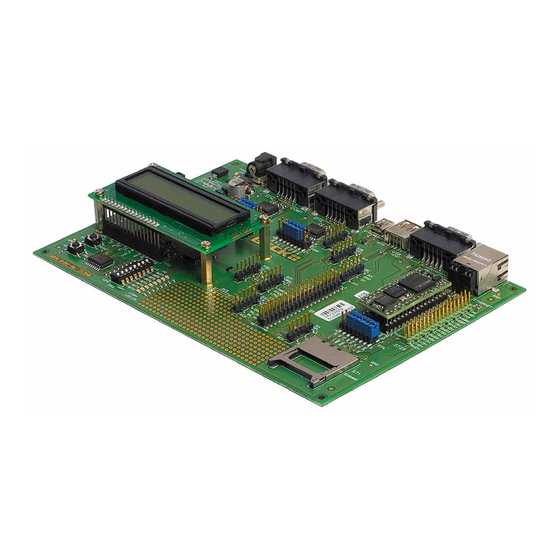
Page 6: Placement Diagram
IPC@CHIP DB54 Hardware Manual V1.1 [04.10.2007] 3. Component layout diagram ©2000-2008 Beck IPC GmbH Page 6 of 24... -
Page 7: Electrical Functions / Interfaces
Switch for the operating voltage of the DB54 Not assembled / optional assignment: e.g. APEM 25136NAH silver ON-ON If the switch is to be assembled later, the 0 Ohm R13 resistor near the SW1must be removed. Top view ©2000-2008 Beck IPC GmbH Page 7 of 24... -
Page 8: Sw18 - Power Fail Button
70hex. To light up an LED you have to write logic 0 to the corresponding port bit, and to switch the LED off you need a logic 1 at the port bit. PCF8574A I/O expander BIT7 BIT6 BIT5 BIT4 BIT3 BIT2 BIT1 BIT0 ©2000-2008 Beck IPC GmbH Page 8 of 24... -
Page 9: Lc-Display
IPC@CHIP DB54 Hardware Manual V1.1 [04.10.2007] A sample program for handling the LED’s and DIP-switch can be obtained from the BECK IPC website. 4.7 LCD Display For more complex visualization, a two-row, 16 character dot matrix, LCD (without backlight) with KS0066 controller/driver is provided on the DB54. -
Page 10: S39 - Pin Header With Power Supplies
Pin assignment (32 pin IC socket) Pin No. Name Description Pin No. RXD1 PFI/PIO9 TXD1 TMRIN1/INT5#/PIO0 CTS1#/PIO12 TMROUT1/INT3/PIO1 RTS1 TMROUT0/PIO10 TXD2/PIO22 TMRIN0/PIO11 RXD2/PIO23 INT1/PIO2 CTS2#/CAN1RX/PIO12 RESETOUT# RTS2#/CAN1TX/PIO20 I2CCLK/PIO31 RXD3/SDI/PIO28 I2CSDA/PIO13 TXD3/SDO/PIO27 CAN0RX RTS3#/SCK/PIO19 CAN0TX ©2000-2008 Beck IPC GmbH Page 10 of 24... -
Page 11: St23 - Ipc@Chip Sc23 Pin Header
PIO pins at S9. To allow WLAN and SD/MMC to coexist at the SPI bus, the WLAN interface uses a different SPI slave select signal (PIO12 / CTS1), so the CTS1 jumper must be removed from S41 for the use of the FK61-WL01 module. ©2000-2008 Beck IPC GmbH Page 11 of 24... - Page 12 PIO12 (CTS1) WLAN_RES# Output PIO2 (INT1) WLAN SPI Connector Pin assignment (1x6 pin header, pitch 2.54mm) Pin No. Name SDO (TXD3 / PIO27) SDI (RXD3 / PIO28) PIO12 (CTS1) SCK (RTS3 / PIO19) ©2000-2008 Beck IPC GmbH Page 12 of 24...
-
Page 13: S30 - I2C Interface
PIO31 3.3V power supply for externally connected expansion Signal reference 4.13 ST15 - RS232 interface COM1 Asynchronous serial interface with RS232 / V24 level and transfer rates up to max. 115200 baud. ©2000-2008 Beck IPC GmbH Page 13 of 24... -
Page 14: S41 - Jumper Array Com1
Pin No. Name Description Pin No. VCC (3.3V) TXD1 to RS232 level converter TXD1-TTL RXD1 from RS232 level converter RXD1-TTL CTS1 from RS232 level converter CTS1-TTL (PIO12) RTS1 to RS232 level converter RTS1-TTL ©2000-2008 Beck IPC GmbH Page 14 of 24... -
Page 15: St14 - Rs232 Interface Com2
TXD2 to RS232 level converter TXD2-TTL (PIO22) RXD2 from RS232 level converter RXD2-TTL (PIO23) CTS2 from RS232 level converter CTS2-TTL (CAN1RX / PIO21) RTS2 to RS232 level converter RTS2-TTL (CAN1TX / PIO20) ©2000-2008 Beck IPC GmbH Page 15 of 24... -
Page 16: S42 - Dcd, Dtr, Dsr Connector
Handshake line. Clear To Send. TTL level Bi-directional PIO18 Output Device Select RTS3 Output Handshake line. Request To Send. TTL level Bi-directional PIO19 Output SPI clock 3.3 power supply (e.g. for externally connected level converter) GND, Signal reference ©2000-2008 Beck IPC GmbH Page 16 of 24... -
Page 17: St1 - Sd/Mmc Interface
PIO18 is reserved as the device-select signal for the SD/MMC interface on the DB54. The appropriate MMC/SD driver must be installed in order to use the SD/MMC interface. This driver can be obtained from the BECK IPC GmbH website. Pin assignment of the SD/MMC connector: Pin No. -
Page 18: St3 - Ethernet Interface
(R22) is provided between the CANLOW and CANHIGH signal (DSUB 9 female). Additionally it is possible to connect the power supply to pin 9 of the DSUB connector S6 by placing a 0 Ohm resistor at R10. # ©2000-2008 Beck IPC GmbH Page 18 of 24... -
Page 19: S38 - Can1 (Com2) Interface
Handshake signal. Clear To Send. TTL level CAN_HIGH Bi-directional Differential CAN signal PIO21 Bi-directional PIO21 RTS2 Output Handshake signal. Request To Send. TTL level 3.3V power supply for external expansions 5V power supply for external expansions ©2000-2008 Beck IPC GmbH Page 19 of 24... -
Page 20: St16 & St13 - Usb Interface
The USB interface of the DB54 has the ability to work in host or device mode. A software driver is needed to use the USB, which can be obtained from the BECK IPC GmbH website. It is not possible to operate the USB in host mode and device mode at the same time. - Page 21 USBP AB_DETECTION Signal descriptions of the USB device interface: Signal name Direction Description USBN Bi-directional Differential USB signal USBP Bi-directional Differential USB signal AB_DETECTION Not connected VCC_USB_DEVICE USB voltage input Signal reference ©2000-2008 Beck IPC GmbH Page 21 of 24...
-
Page 22: Technical Data
31mm x 135mm x 195mm (+/-1 mm) 5.3 Electromagnetic data This product is a development board without the CE mark. 5.4 Electrical data Input voltage: 9…30 VDC Current consumption (DB54 without expansions): max. 1.7 W ©2000-2008 Beck IPC GmbH Page 22 of 24... -
Page 23: General Conditions Of Use
Use of the development board outside the specified environment is the responsibility of the user and shall be carried out at his or her own risk, exempting Beck from any liability. Claims by the user for compensation against Beck in conjunction with the use of this product shall be excluded. -
Page 24: History
INTELLECTUAL PROPERTY INFRINGEMENT. BECK IPC GmbH MAKES NO WARRANTY OF MERCHANTABILITY OR Right to make changes - Beck IPC GmbH reserves the right to SUITABILITY FOR ANY PURPOSE. make changes without notice in the products, including software, described or contained herein in order to improve design and/or BECK IPC GmbH shall not be responsible for any errors that performance.
Need help?
Do you have a question about the IPC@CHIP DB54 and is the answer not in the manual?
Questions and answers