Table of Contents
Advertisement
Quick Links
Advertisement
Table of Contents

Summary of Contents for Sensor Partners LAM71
- Page 1 Sensor Partners LAM71 Laser Distance Sensor Manual...
- Page 2 User advice Dear User, Please read this operating manual carefully before starting to operate the LAM71 laser distance meter. This is the only way to make sure that you will be able to make full use of the capabilities of your new laser distance meter, and to prevent any damage caused by operating errors.
-
Page 3: Table Of Contents
6.3.1 ID recognition ........................17 6.3.2 ID? – Online help ....................... 17 Operation modes ....................... 18 6.4.1 DM – single distance measurement ................. 18 6.4.2 DT – Continuous distance measurement (distance tracking) ........... 18 Status ..........................19 LAM71, Release 001_Revision 001... - Page 4 Setup parameters ......................22 6.6.1 AS – Autostart function ..................... 22 6.6.2 BR – Baud rate ........................22 6.6.3 DR – LAM71 restart (device reset) ..................23 6.6.4 GN – Setup GAIN ....................... 23 6.6.5 MF – Measurement frequency ..................24 6.6.6 MW –...
-
Page 5: General Information
1.3 Integration of device in a system The combination or integration of the device, LAM71, with or into a system not provided and authorized by Sensor Partners for the respective device may result in errors of the data transmission, including but not limited to failures in the total measurement range, accuracy, repeatability, connectivity or transfer speed of data. -
Page 6: Safety Advice
Please read the safety and operating advice carefully, and observe the advice when operating the LAM71 laser distance measurement device. The LAM71 is equipped with a laser diode emitting in the infrared spectrum, which is not visible to the human eye. -
Page 7: Transport And Storage
2.3 Transport and storage The laser distance meter LAM71 is delivered in standard packaging. All kinds of transport are permitted. It is recommended to store the unit inside the transport packaging until it is used. Please observe the storage conditions. -
Page 8: Intended Use/ Conditions
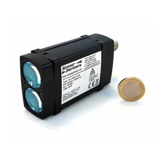
2. Measurements through glass, optical filters, Plexiglas or other translucent materials can re- sult in measurement errors. 3.3 Warning signs and type plates Laser label The LAM71 works with a class 1 laser. Type plate The type plate shown is an example. Serial number (SN) may differ from this image. -
Page 9: Device Description
Interface solutions like RS232, RS422, analog output and switching outputs are integrated. LAM71 is designed for an operating temperature (ambient temperature) of as low as -40°C up to +60°C. The heating element ensures the operating temperature of the components and free optics (no con- densation) of the LAM71. -
Page 10: Laser Beam Image
5.8 mrad The table below shows the size of the laser spot on the target in dependence on the distance. Installation of LAM71 Lenses of LAM71 are vertical about each other. Laser spot width Laser spot height Footprint laser spot... -
Page 11: Installation And Start Of Operation
5 Installation and start of operation 5.1 Preparatory work prior to installation • Remove the packaging of the LAM71 and accessories. • Check the delivery for completeness. • Examine the device and the accessories for damage. 5.2 Mechanical installation The LAM71 can be screwed on 3 positions:... -
Page 12: Connector Pin Assignment
Overvoltage protection is provided up to a maximum of 42 V DC. The shield of the cable should be connected to the connector housing. Open, unused cable wires must be insulated. LAM71 connector: M12-A male panel mount connector 09 3491 970 12 Producer: Binder Interface cable see chapter 4.2... -
Page 13: Serial Interface Rs232 / Rs422
Before using the serial interface RS232 or RS422 the user has to check the connection of PIN 3 (white). RS232 PIN 3 not connected RS422 PIN 3 connected with PIN 12 (GND) RS232 Figure 2 Wiring of serial interface RS232 RS422 Figure 3 Wiring of serial interface RS422 LAM71, Release 001_Revision 001... -
Page 14: Parameter Setup And Measuring Operation
6 Parameter setup and measuring operation 6.1 General information The LAM71 is parameterized using the serial interface. Precondition for programming via UART is a con- nection provided by a terminal program (e.g. HyperTerminal, Tera Term). The set parameters are stored in an EEPROM. -
Page 15: Measurement Involving Moving Targets
6.2 Measurement involving moving targets Where measurements involve a moving object or the LAM71 is moved during measuring, this will have an impact on the accuracy of the measured value. This must be observed particularly when calculating average values (parameter SA). -
Page 16: Operation Modes
6.4 Operation modes 6.4.1 DM – single distance measurement LAM71 performs one measurement and then waits for new commands. The duration of the measurement depends on the number of preset measuring values SA and the pre- set measuring frequency MF. -
Page 17: Status
Query: Example: TP 048.4 The user of the LAM71 must make sure that the stated ambient temperature (operating tempera- ture) is adhered to. In case of deviations below or above the temperature range no measurement is possible. The LAM71 will send an error message. -
Page 18: Pa - Display Parameter Setting
1.000 0.050 1 digital out[Q2]....0.000 1.000 0.050 1 analog out[QA]....0.000 1.000 receiver gain[GN]....0 serial baud rate[BR].....115200 serial output format[SD]..dec (0), value+amplitude (1) unit for binary output[UB]..1000.000 serial output terminator[TE]..0Dh0Ah (0) autostart command[AS]....DT select target[ST]....0/first recalibration timing[TC]..1 sec/enabled LAM71, Release 001_Revision 001... -
Page 19: Pr - Parameter Reset
1.000 0.050 1 digital out[Q2]....0.000 1.000 0.050 1 analog out[QA]....0.000 1.000 receiver gain[GN]....0 serial baud rate[BR].....115200 serial output format[SD]..dec (0), value (0) unit for binary output[UB]..1000.000 serial output terminator[TE]..0Dh0Ah (0) autostart command[AS]....DT select target[ST]....0/first recalibration timing[TC]..1 sec/enabled LAM71, Release 001_Revision 001... -
Page 20: Setup Parameters
6.6 Setup parameters Transfer of the settings to the LAM71: Command + terminator 0x0D (ENTER). In case of commands with one parameter, that parameter is entered directly or separated by a space (0x20). In case of commands with several parameters, those are separated from each other by a space (0x20). -
Page 21: Dr - Lam71 Restart (Device Reset)
6.6.3 DR – LAM71 restart (device reset) DR executes a cold start of the LAM71 and practically simulates a voltage interruption. This command is useful when the autostart command has been changed. Input: Response: reset device wait...<0> ➔ Continue with execution of command in parameter AS 6.6.4 GN –... -
Page 22: Mf - Measurement Frequency
(SD) in the tables below. If measuring frequency will be higher as the values in the table some measured values will be lost. Please double check with a new setting of measur- ing frequency MF the BR setting. LAM71, Release 001_Revision 001... - Page 23 SD 0 2 SD 0 3 Baud rate Maximum output frequency = MF max (Hz) 9600 19200 1000 115200 2000 1400 1300 230400 4100 2750 2500 1850 460800 7300 4750 4350 3300 921600 12200 7850 6480 5000 2000000 LAM71, Release 001_Revision 001...
-
Page 24: Mw - Measurement Window
0 or 1 Standard: -71.000 71.000 0 Output: MW -71.000 71.000 0 LAM71 does not perform a plausibility check of the preset measurement window. It is the responsibil- ity of the user to set the correct parameters. Output values: Measuring window distance <... -
Page 25: Of - Offset
0.001 (-250.000m … +250.000m; resolution 1mm = 0.001m) Standard: 0.000 Output: OF 0.000 LAM71 does not perform a plausibility check of the preset offset. It is the responsibility of the user to set the correct parameters. LAM71, Release 001_Revision 001... -
Page 26: Qa - Analogue Output
If current/voltage is to be converted, there must be a load resistor of < 500 Ohms/0.5 W (12 V of inter- nal voltage --> max. measuring current of 0.024 A) between current output QA and GND Fig. 5 Wiring of analogue output QA LAM71, Release 001_Revision 001... - Page 27 0.001 Standard: 0.000 1.000 The LAM71 does not perform a plausibility check of the QA settings. It is the responsibility of the user to set the correct parameters. The measurement window MW (see 6.6.6) applies to the analogue output as well.
-
Page 28: Q1/ Q2 - Switching Output
Q1/Q2 parameterises the behaviour of the switching outputs. The parameters include the beginning w of the measuring range when the output switches, the length x of the measuring range, the hysteresis y as well as the logic behaviour z. LAM71, Release 001_Revision 001... - Page 29 = 0 or 1 Query: Q1 or Q2 Set: Q1w x y z or Q2w x y z Standard: 0.000 1.000 0.050 1 The LDS30 does not perform a plausibility check of Q1 or Q2 settings respectively. LAM71, Release 001_Revision 001...
-
Page 30: Sa - Mean Value Average
15000 1500 + 19 15000 15000 1000 For SA will be used all valid measured distance values. If distance is out of the measurement win- dow MW the measured value will ignored for the SA calculation. LAM71, Release 001_Revision 001... -
Page 31: So - Set Offset
For binary output distance value is available only (not temperature and/ or signal quality). In conjunction with the baud rate, the output format determines the maximally possible output speed of measured values. If a higher measurement frequency is set, the results of some measurements will not be put out. LAM71, Release 001_Revision 001... - Page 32 3.38 m Signal * 2 = Temperature - 40 = 53°C The binary distance range will determined by parameter UB. If the distance value is below or above the distance range, the binary output is 0! LAM71, Release 001_Revision 001...
-
Page 33: Se - Error Mode
The LAM71 does not perform a plausibility check of the preset error mode. 6.6.14 ST – Select Target ST defines the target which should be detected. LAM71 is able to detect 4 different target in maximum. Selection will be done between the first or the last detected target. -
Page 34: Tc - Time Calibration
Up to a Measuring frequency of approx. 35 kHz the calibration will be done without any influences of the output frequency. Between 35 k Hz and 40 kHz it could be possible that the data output will interrupt for one (1) distance output every x seconds (x= parameter of TC). LAM71, Release 001_Revision 001... -
Page 35: Te - Terminator
0x0D 0x0A CR LF 0x0D 0x0A 0x02 0x03 0x09 HTab 0x20 Space 0x2C Single quote 0x3A Colon 0x3B Semicolon When an invalid character is entered, it will not be set. The previous terminator will be maintained. LAM71, Release 001_Revision 001... -
Page 36: Ti + To Trigger
External trigger signal will be sent → start of measurement DM in accordance with parameter TI. 2. Trigger output / e.g. connection between 2 LAM71: The output trigger signal of the 1. LAM71 (parameterized with TO) starts a single measurement DM of the second LAM71 (parameterized with TO). - Page 37 Maximum frequency of external trigger signal for Trigger IN (TI): 30 k Hz If the trigger frequency is too high, no measurement value can be determined. The output is E02. The trigger frequency must be reduced. LAM71, Release 001_Revision 001...
- Page 38 (from HIGH to LOW) every edge Query: Set: TO x Value range parameter x: 0, 1, 2 Standard: Output: Trigger (output) [TO]: 0 Figure 7 Wiring of trigger output Maximum frequency of Trigger OUT (TO) = MF (Measurement frequency) LAM71, Release 001_Revision 001...
- Page 39 First trigger signal starts a continuous measurement (DT) with the rising edge. The delay between the triggersignal and start of measurement is 10 msec. Next trigger signal stops a continuous measurement (DT) with the rising edge. The delay between the triggersignal and stop of measurement is 10 msec. LAM71, Release 001_Revision 001...
-
Page 40: Ub - Unit For Binary Output
The measuring range will be depicted with 14 signed bits. Distance value (binary) = Distance (mm) / UB Distance range (binary) : -8192 < Distance < 8191 If the distance value is below or above the distance range, the binary output is 0! LAM71, Release 001_Revision 001... -
Page 41: Serial Interface And Communication Software
• The response to commands with parameters outside of the valid value range is the respective command including the current parameters. • The response to unknown commands and faulty parameter formats is a “?” (0x3F). LAM71, Release 001_Revision 001... -
Page 42: Error Processing
The measuring mode DT could be stopped with <ESC> in the case of error and error message output too. The communication with LAM71, e.g. parameterizing, reset or start of new measurement, will be not influence by the error message. If DT is started and the error did not reset automatically, the error message will be outputted again. -
Page 43: Technical Data
Measuring range for special targets, e.g. Scotchlite Cube Accuracy can be ± 100 mm for close-up ranges up to 1 m. Repeatability ± 50 mm at measurement distance 70 m. LAM71, Release 001_Revision 001... - Page 44 Sensor Partners Sensor Partners BV – Head office James Wattlaan 15 5151 DP Drunen The Netherlands Phone: +31 416 378239 Email: info@sensorpartners.com Internet: www.sensorpartners.com...
Need help?
Do you have a question about the LAM71 and is the answer not in the manual?
Questions and answers