Table of Contents
Advertisement
OCTOBER 2003
Application AND COMMISSIONING
MANUAL FOR NUMERICAL BIASED
DIFFERENTIAL PROTECTION RELAY
TYPE - MIB202
EASUN REYROLLE LIMITED
1
Advertisement
Table of Contents

Summary of Contents for EASUN REYROLLE LIMITED MIB202
- Page 1 OCTOBER 2003 APPLICATION AND COMMISSIONING MANUAL FOR NUMERICAL BIASED DIFFERENTIAL PROTECTION RELAY TYPE - MIB202 EASUN REYROLLE LIMITED...
- Page 2 ISSUE NO Issue DATE OF ISSUE 01 - 10 - 2003 DEPARTMENT...
-
Page 3: Table Of Contents
CONTENTS PAGE APPLICATION 4 - 9 INSTALLATION 10 - 19 COMMISSIONING 20- 25 DRAWING... -
Page 4: Application
Compensation features and also with Instantaneous Differential Highset Element for two winding Power Transformer and AutoTransformers. MIB202 relay, which can be used to operate for internal faults, like phase to phase, phase to earth and inter turn faults in the Transformers. - Page 5 1.2 DIFFERENTIAL BIAS SLOPE: Some unbalance current will appear in the differential circuit of the relay for predictable reasons, e.g. due to the transformer tap position and to CT errors. The current will increase with increasing load or through fault current in the transformer so, to maintain stability, the biasing current must increase proportionately.
- Page 6 3.0 MAGNETIZING INRUSH RESTRAINT: Second Harmonic quantities are calculated from the signal I1 - I2 to provide an inhibit signal to prevent the protection operating for magnetizing inrush conditions. Magnetizing inrush on any phase will inhibit all three phases. 4.0 INTERPOSING CT MULTIPLIER (HV AND LV SIDE): This range of settings enable the effective ratio of the HV &...
- Page 7 7.0 TYPICAL RELAY SETTING CALCULATION Power Transformer Details: Voltage = 132 / 33KV Rating = 60MVA Tap Changer = +5% - 15% Vector Group = Yd1 Current Transformer Details: CT Ratio For HV Side = 300/1 For LV Side = 1200/1 Calculation: HV rated current = 60MVA / (132 * 1.732)
- Page 8 8.0 INTERPOSING CT SELECTION GUIDE Power Transformer Vector Group Interposing Interposing CT Selection CT Selection Yy0, YNy0, Yyn0, YNyn0, Ydy0, Yd1,30° Yd1,30° Yndy0, Ydyn0, YNdyn0 Yd1, YNd1 Yd1,30° Yy0,0° Yd1, YNd1 + Earthing Transformer Yd1,30° Ydy0,0° Yy2, YNy2, Yyn2, YNyn2, Ydy2, Yd3,90°...
- Page 9 Yd11, YNd11 Yd11,-30° Yy0,0° Yd11, YNd11 + Earthing Transformer Yd11,-30° Ydy0,0° Dy1, Dyn1 Ydy0,0° Yd11,-30° Dy1, Dyn1 + Earthing Transformer Ydy0,0° Yd11,-30° Dy3, Dyn3 Ydy0,0° Yd9,-90° Dy3, Dyn3 + Earthing Transformer Ydy0,0° Yd9,-90° Dy5, Dyn5 Ydy0,0° Yd7,-150° Dy5, Dyn5 + Earthing Transformer Ydy0,0°...
-
Page 10: Installation
INSTALLATION 1.1 UNPACKING On receipt, remove the relay from the carton box in which it was received and inspect it for obvious damage. It is recommended that the relay is not removed from the relay case. To prevent the possible ingress of dirt, the sealed polythene bag should not be opened until the relay is to be used. - Page 11 Thus mechanical interlock is provided to avoid unauthorized setting change. 2.1 CURRENT TRANSFORMER TAP SELECTION MIB202 relays are suitable for 1A or 5A application. However the relays are internally wired for either 1A or 5A as per the customer requirement.
- Page 12 2) The black colour wire “9A” is inserted to 9 terminal of TB. 3) First, carefully lift the PVC boot of the wire by means of a tool (like nose pliers) to expose terminal 9A. 4) Hold the crimp by means of the same tool at the crimp point and lift to remove from the fixed terminal.
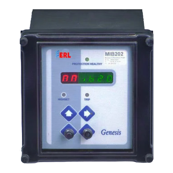
- Page 13 - Enter / Reset / Cancel / To check Version SETTING INSTRUCTIONS How to operate HMI ♦ Remove the front cover by unscrewing the four knurling screws. ♦ Apply DC supply. Terminals 22,24 and 23 are for positive, negative and earth respectively as per relay rating. When the relay powers up it takes few seconds to complete the self-test routine.
- Page 14 - Vector group compensation setting for LV windings - Highset setting DIFFERENTIAL INITIAL SETTINGS Setting Range: 10% to 50% in steps of 5% (The setting refers to % of rated nominal CT secondary rating) Pressing (represents initial setting is 20% of rated nominal current) display will appear, press (Submenu LED On) to get the Sub menu.
- Page 15 3.5 CURRENT AMPLITUDE CORRECTION SETTINGS 3.5.1 HV side ICT multiplier Setting range: 0.50 to 2.50 in steps of 0.01. Pressing repeatedly Main menu (represents current amplitude correction setting of HV winding current input is 1.00), press key (Submenu LED On) to get the Sub menu.
- Page 16 3.6.2 Vector group compensation on LV windings Setting available: Yy0, Yy2, Yy4, Yy6, Yy8, Yy10, Yd1, Yd3, Yd5, Yd7, Yd9, Yd11, Ydy0 and Ydy6 Pressing repeatedly Main menu (represents Vector group compensation for LV winding is Yy0), press key (Submenu LED On) to get the Sub menu. Pressing key changes the Vector group compensation setting desired by increment or decrement.
-
Page 17: Commissioning
5.0 TO CHECK THE RELAY VERSION Press key four times, example of relay version display is as follows: Represent MIB 202-relay version 1 To get back the main menus press key. 6.0 TO CANCEL SETTING WHILE CHANGING (CANCEL) While the particular setting is being changed (using key) with Submenu LED ON, by pressing key, the original setting is... - Page 18 To enter into this mode, the sub menu key has to be pressed for around 10 secs. After the time delay the relay front LED will display the following signals as in the order given below by pressing the key. - Indicates HV winding r –...
- Page 19 - Indicates HV winding b – phase relay current after amplitude and phase angle (Vector group correction) correction. - Indicates LV winding b – phase relay current after amplitude and phase angle (Vector group correction) correction. - Indicates b – phase restraining current - Indicates b –...
- Page 20 COMMISSIONING 1. REQUIRED TEST EQUIPMENT'S • 500V insulation test sets. • Variable secondary injection current source rated 10A or greater. • Variable voltage source. • Time interval meter. • A DC supply with a nominal voltage within the working range of the relays DC auxiliary supply ratings.
- Page 21 5.2 SECONDARY INJECTION Select the required relay configuration and settings for the application. Note that the MIB202 relay can be connected either as 1A or 5A-rated device. The user should check this before commencing secondary testing.
- Page 22 These tests check the ratio and polarity of the star connected CT's with or without a neutral CT and also their connections to the correct terminals of the MIB202 input modules. 5.4 PUTTING INTO SERVICE After completing all tests satisfactorily, the relay should be put...
- Page 23 3. Check the relay healthy indication/display. 4. Replace the relay cover. 5. Insert the trip links. 6. Perform trip test by secondary injection. 7. Remove all test connections MIB202 Bias Current Operate Current Fig 1 Circuit For Checking the Bias Characteristics...
- Page 24 Bias Current, Ammeter Al Multiples of rated Initial Bias current In Settings Settings Operate Current, Ammeter A2 Amps 0.10 0.11 0.16 0.21 2.26 0.20 0.21 0.33 0.44 0.56 0.30 0.35 0.53 0.71 0.88 0.40 0.50 0.75 1.00 1.25 0.50 0.67 1.00 1.33 1.67...
- Page 25 S1 S2 Dyn11, 30º 440V AC Source D.C SUPPLY Fig 2 Primary Injection Test Circuit...
-
Page 26: Drawing
2. Terminal No.23 (Earth) is to be connected directly to earthbar. Drawing No. :- 8662W20001 WIRING DIAGRAM FOR MIB 202 RELAY CHECKED EASUN REYROLLE LIMITED., No. Sig. DATE Sig. DATE DATE Sig.