
Subscribe to Our Youtube Channel
Related Manuals for Thermon Tracenet Genesis


Summary of Contents for Thermon Tracenet Genesis
- Page 1 TRACENET GENESIS CONTROL AND MONITORING SYSTEM Installation, Operation & Maintenance Guide...
- Page 2 The information in this guide is furnished for informational use only, is subject to change without notice, and should not be construed as a commitment by Thermon. Thermon assumes no responsibility or liability for any errors or inaccuracies that may appear in this guide.
-
Page 3: Table Of Contents
Appendix E: Recommended Wiring For RS 485 Communications ...........35 NOTE: The TraceNet Command Communications Operating Instructions are addressed in a separate document covering TraceNet Genesis, as well as TN, TCM18, TC1818, TCM2, TC202, TC201, TC101, and ECM. TraceNet Genesis requires TraceNet Command Version 2.3.0+ for operation. -
Page 4: Section 1: Genesis Introduction And Overview
• If the servicing of removable electrical connectors is TraceNet Genesis heat tracing control panel. This guide is to be conducted, then make certain the area is free of to be sent in conjunction with the project specific panel explosive atmospheres. -
Page 5: Heat Trace And Insulation Installation
All heat trace circuits and insulation shall be installed in accordance with project installation details provided. In addition, refer to the Electric Heat Tracing Maintenance and Troubleshooting Guide (Thermon Form No. 20745) for general procedures and installation tips. RTD Installation and Wiring RTD control sensors should generally be installed on the process lines (see figure below) or in ambient (where ambient sensing is applied) in a location that is most representative of the entire heat trace circuit. -
Page 6: Section 3: The Genesis System-Overview
Section 3: The Genesis System—Overview The TraceNet Genesis system modules include a Human Machine Interface, or HMI; at least one (1) Distributed Control Module, or DCM; at least one (1) Distributed Temperature Module, or DTM; and at least one (1) Input-Output Module, or IOM. -
Page 7: 4: The Iom
3.1.4: The IOM The IOM (Input-Output Module) is a DIN rail mountable input/output module with one (1) dedicated system fault alarm output. (Outputs to signal a variety of conditions such as circuit trips, low temperature alarms, ground/earth leakage alarms, and high temperature alarms. -
Page 8: The Genesis Hmi Screens
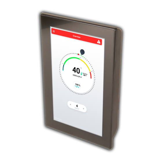
3.2 The Genesis HMI Screens The following section details configuration of the TraceNet Genesis HMI module. 3.2.1: Circuit Overview Provides a quick status of all circuits at a glance while highlighting one circuit a time with more detail. Each dot around the perimeter of the selector dial represents one circuit. - Page 9 3.2.2: Main Menu To access the Main Menu, touch the ‘hamburger’ icon in the upper left corner of any screen. Use the Menu to navigate between Overview, Circuit List, Global Settings and the System screen as well as to switch between night and day color profiles and to Import and Export configurations, isometrics, etc.
- Page 10 Lower Setting Description Acceptable Upper Limit Units Limit Number of Total number of circuits to display in Number None Active Circuits Overview 3.2.4: Global Settings Gregorian System Date Calendar; 24 hr Current Time and Date Global Settings can be reached from and Time time;...
- Page 11 3.2.5: Dashboard/Circuit Details The dashboard provides a comprehensive single circuit view. It includes the circuit number, tag, pipeline number, or other status as well as real-time temperature, heater current, ground leakage current and related alarm set points. This screen can be reached by tapping a circuit in the Overview or the Circuit List. The limits below define the lowest and highest possible values.
- Page 12 Lower Setting Description Available Options Upper Limit Units Limit Alpha-numeric, Upper/ User defined Alpha-numeric Circuit Name Lower Case, hyphen, Characters Identifier unique to circuit 3.2.6: Circuit Settings Process Tag User defined alpha-numeric Settings on a per circuit basis (distinct Identifier For from set points) can be found here.
- Page 13 3.2.7: Circuit History Plots up to six months of temperature and current data with accompanying set point changes. 3.2.8: Circuit ISO Use multi-touch pinch and zoom gestures to view the ISO (isometric drawing) for the circuit. 3.2.9: Circuit Notes Useful notes can be stored here for any purpose such as for operators across shifts or for maintenance (requires log-in).
- Page 14 3.2.11: Circuit Alarm List The Circuit Alarm List can be reached from the Menu. Here, live panes for each circuit in alarm, appear in a list organized with tabs for all alarms, by alarm type or by process. To acknowledge an alarm, tap Ack on the left of the circuit pane.
-
Page 15: Setting Addresses And Configuring Genesis Dcm And Dtm
3.3: Setting Addresses and Configuring Genesis DCM and DTM The Genesis DCM (Distributed Control Module), DTM (Distributed Temperature Module), and IOM (Input Output Module) each have a two-digit address code. The two (2) digit code used to identify each module through the CAN bus to the HMI (Human Machine Interface). -
Page 16: Section 4: Genesis Control Options And Examples
Example of "On-Off" Ambient Sensing Control: situation calls for 50% power, then the controller cycles on As a third control mode option, the TraceNet Genesis panel and off 50% of the time to achieve this energy delivery. may be configured for Ambient “On-Off” Control. In this case, There is a “Power Clamp”... -
Page 17: Proportional Control And Power Clamp
All heat trace circuits should be properly terminated and • Without touching the multi-meter/instrument energize megger tested prior to energizing the TraceNet Genesis the equipment and read the values indicated on the control panels. In addition, all pipes should be insulated multi-meter/instrument. -
Page 18: Appendix A: Quick Start Guide For The Genesis Control And Monitoring System
Appendix A: Quick Start Guide For The Genesis Control And Monitoring System TraceNet Genesis CONTROL AND MONITORING SYSTEM The TraceNet Genesis HMI serves OVERVIEW "HAMBURGER" MENU as the central user interface. • View Status For 72 Circuits On Dashboard •... - Page 19 Corporate Headquarters: 7171 Southwest Parkway • Building 300, Suite 200 • Austin, TX 78735 • Phone: 512-690-0600 For the Thermon office nearest you visit us at . . . www.thermon.com Form TEP0217-0219 © Thermon, Inc. • Printed in U.S.A. • Information subject to change.
-
Page 20: Appendix B: Genesis Specifications Guide With Component Limits And Specifications
Appendix B: Genesis Specifications Guide With Component Limits And Specifications TRACENET GENESIS CONTROL AND MONITORING SYSTEM SPECIFICATION GUIDE... - Page 21 ETL Listed Conforms to: UL STD. 508A. UL STD. 12.12.01 Certified to: CSA STD. C22.2 NO. 14. CSA STD. C22.2 NO. 213 * Additional cabinet types are available. Contact Thermon for details. ** Rating based on extended heat sinks. Multiple single pole relays may be used for two...
- Page 22 Circuit History For Trending Circuit Dashboard 581 mm (2-1/4") PRODUCT FEATURES • TraceNet Genesis HMI Is IP66 • Module operates in a wide range of ambient conditions • Multi-language capability Circuit Isometric Drawing "Glove Touch" User Interface • Color display utilizes LED backlighting to maximize service life and is additionally programmable for “sleep mode”...
- Page 23 (20 to 6 AWG), 630 Vac 41 mm (1-5/8") Printed circuit board ......... conformal coated 152 mm Heat sink ..............Type 4X, IP66 (6") 1. DIN-rail mounted terminal blocks for line voltage to be off PC board. 267 mm (10-1/2") 483 mm (19") THERMON.COM...
- Page 24 Maximum RTD capacity .............. 6 Operating ambient temp. range . -40°C (-40°F) to 100°C (212°F) Terminal connections ......up to 2.5 mm (28-12 Awg) 1. For designs that allow operation in ambient conditions below -40°F (-40°C) contact Thermon.. CONNECTION DIAGRAM CONNECTION DIAGRAM Alarm Relay...
- Page 25 TRACENET GENESIS CONTROL AND MONITORING SYSTEM TRACENET COMMAND Genesis Systems communicate via Ethernet to the Thermon TraceNet Command electric tracing circuit monitoring software. TraceNet Command provides centralized electric tracing information for all panels in a facility, such as: TCM18 • Heat tracing circuit status •...
- Page 26 -40°F (-40°C). J = 72 x 48 x 24 (1829 x 1219 x 610) 2. Contact Thermon for additional information. H = 72 x 60 x 24 (1829 x 1524 x 610) I = 72 x 72 x 24 (1829 x 1829 x 610)
- Page 27 Corporate Headquarters:100 Thermon Dr • PO Box 609 San Marcos, TX 78667-0609 • Phone: 512-396-5801 • 1-800-820-4328 For the Thermon office nearest you visit us at . . . www.thermon.com Form TEP0212-0718 © Thermon, Inc. • Printed in U.S.A. • Information subject to change.
-
Page 28: Appendix C: Troubleshooting Tips For Reliable Electrical Heat Trace Performance
Appendix C: Troubleshooting Tips For Reliable Electrical Heat Trace Performance Troubleshooting Tips Troubleshooting tips are provided here as a beginning point in correcting start-up issues and clearing out alarm and trip events. High Temperature Reading/Alarm The following summarizes some of the possible causes and solutions for heat tracing high temperature alarms. Possible Cause Recommended Solutions Temperature of product in process... - Page 29 Low Temperature Reading/Alarm The following summarizes some of the possible causes and solutions for heat tracing low temperature readings/alarms. Possible Cause Recommended Solutions Temperature of product in process Let process operations return to normal conditions and then recheck for line is below the alarm set point or alarms.
- Page 30 RTD Sensor Alarm The following summarizes some of the possible causes and solutions for a heat tracing RTD sensor reading alarm. Possible Cause Recommended Solutions RTD connections are wired improperly Confirm wiring and connections are correct. or have become loose. RTD has failed open or has extremely Perhaps lightning has damaged the sensor? Maybe the piping has had high resistance or RTD has failed...
- Page 31 High Current Readings/Alarms The following summarizes some of the possible causes and solutions for heat tracing high current readings or alarms. Possible Cause Recommended Solutions Self regulating heater or power limiting Increase high current alarm set point (if approved by project engineer). heater current may exceed set value For startup operation current alarm nuisances, it may also be desirable to during normal operation or start-up...
- Page 32 Low Current Readings/Alarms The following summarizes some of the possible causes and solutions for heat tracing low current readings or alarms. Possible Cause Recommended Solutions Self-regulating or power limiting Decrease low current alarm setpoint (if approved by project engineer). heater may be operating at higher than design pipe temperatures due to processing con- ditions and thus heaters may be drawing lower current...
- Page 33 (if approved by project engineer). If issues remain after exercising all these possible causes and solutions for heat tracing alarms and trips, contact your nearest Thermon engineering center for assistance and/or for arranging for field service.
-
Page 34: Appendix D: Genesis Modbus Memory Reference
Appendix D: Genesis Modbus Memory Reference TraceNet Genesis Panel Customer Modbus Memory Map Circuit Settings FUNCTION Memory Location Description Allowed Values (CKT1) CODE DEC HEX Add CKT# x 100 to Base Memory Location to get the MODBUS Data Address CKT 1's Maintain Temp = 101+ 1*100 = 101 (0x0064) -
Page 35: Appendix E: Recommended Wiring For Rs 485 Communications
Add CKT# x 100 to Base Memory Location to get the MODBUS Data Address (Values offset from the CANBus memory map by -80 eg alarms in CANBus is memory location 185, in Modbus is 185) 0x064 Control Temperature for the DCM Value x10 RTD Reading for the DTM This location on the DCM is the temperature that it has decide to... - Page 36 Corporate Headquarters: 7171 Southwest Parkway • Building 300, Suite 200 • Austin, TX 78735 • Phone: 512-690-0600 For the Thermon office nearest you visit us at . . . www.thermon.com PN50881-0219 © Thermon, Inc. • Printed in U.S.A. • Information subject to change.
Need help?
Do you have a question about the Tracenet Genesis and is the answer not in the manual?
Questions and answers