Table of Contents
Advertisement
Advertisement
Table of Contents

Summary of Contents for CFM CFM56 Series
- Page 1 TRAINING MANUAL CFM56-ALL BORESCOPE INSPECTION SEP 2003 CTC-229 Level 3...
- Page 2 CFM56-ALL TRAINING MANUAL Published by CFMI CFMI Customer Training Center CFMI Customer Training Services Snecma Services GE Aircraft Engines Site de Melun-Montereau, Customer Technical Education Center Aérodrome de Villaroche 123 Merchant Street Chemin de Viercy, B.P. 1936, Mail Drop Y2 77019 - Melun Cedex Cincinnati, Ohio 45246 FRANCE...
- Page 3 CFM56-ALL TRAINING MANUAL THIS PAGE INTENTIONALLY LEFT BLANK EFFECTIVITY Page 2 GENERAL ALL CFM56 ENGINES Issue 01 CFMI PROPRIETARY INFORMATION...
- Page 4 For authorized maintenance practices and specifications, consult pertinent maintenance publications. The information (including technical data) contained in this document is the property of CFM International (GE and SNECMA). It is disclosed in confidence, and the technical data therein is exported under a U.S. Government license.
- Page 5 CFM56-ALL TRAINING MANUAL THIS PAGE INTENTIONALLY LEFT BLANK EFFECTIVITY Page 4 GENERAL ALL CFM56 ENGINES Issue 01 CFMI PROPRIETARY INFORMATION...
-
Page 6: Lexis
CFM56-ALL TRAINING MANUAL LEXIS EFFECTIVITY Page 5 LEXIS ALL CFM56 ENGINES Issue 02 CFMI PROPRIETARY INFORMATION... - Page 7 CFM56-ALL TRAINING MANUAL AIR TRANSPORT ASSOCIATION AIRCRAFT AUTOTHROTTLE COMPUTER ALTERNATING CURRENT ATHR AUTO THRUST ACARS AIRCRAFT COMMUNICATION ABORTED TAKE OFF ADRESSING and REPORTING SYSTEM AVM AIRCRAFT VIBRATION MONITORING ACAU AIR CONDITIONING ACCESSORY UNIT ACMS AIRCRAFT CONDITION MONITORING SYSTEM BITE BUILT IN TEST EQUIPMENT ACS AIRCRAFT CONTROL SYSTEM BMC BLEED MANAGEMENT COMPUTER ADC AIR DATA COMPUTER...
- Page 8 CFM56-ALL TRAINING MANUAL CFMI JOINT GE/SNECMA COMPANY (CFM DAR DIGITAL ACMS RECORDER INTERNATIONAL) DIRECT CURRENT CENTER OF GRAVITY DCU DATA CONVERSION UNIT Ch A channel A DCV DIRECTIONAL CONTROL VALVE BOEING Ch B channel B DEU DISPLAY ELECTRONIC UNIT CHATV...
- Page 9 CFM56-ALL TRAINING MANUAL EFH ENGINE FLIGHT HOURS FDAMS FLIGHT DATA ACQUISITION & EFIS ELECTRONIC FLIGHT INSTRUMENT SYSTEM MANAGEMENT SYSTEM EGT EXHAUST GAS TEMPERATURE FDIU FLIGHT DATA INTERFACE UNIT EHSV ELECTRO-HYDRAULIC SERVO VALVE FDRS FLIGHT DATA RECORDING SYSTEM EICAS ENGINE INDICATING AND CREW FDU FIRE DETECTION UNIT ALERTING SYSTEM FEIM FIELD ENGINEERING INVESTIGATION MEMO...
- Page 10 CFM56-ALL TRAINING MANUAL FWD FORWARD HPTC HIGH PRESSURE TURBINE CLEARANCE HPTCCV HIGH PRESSURE TURBINE CLEARANCE CONTROL VALVE g.in GRAM X INCHES HPTN HIGH PRESSURE TURBINE NOZZLE GENERAL ELECTRIC HPTR HIGH PRESSURE TURBINE ROTOR GEAE GENERAL ELECTRIC AIRCRAFT HERTZ (CYCLES PER SECOND) ENGINES GEM GROUND-BASED ENGINE MONITORING GROUND IDLE (G/I)
- Page 11 CFM56-ALL TRAINING MANUAL KILOGRAMS PER HOUR MCT MAXIMUM CONTINUOUS MDDU MULTIPURPOSE DISK DRIVE UNIT MEC MAIN ENGINE CONTROL LEFT milsD.A. Mils DOUBLE AMPLITUDE LEFT HAND MILLIMETERS lbs. POUNDS, WEIGHT MMEL MAIN MINIMUM EQUIPMENT LIST LCD LIQUID CRYSTAL DISPLAY AIRCRAFT SPEED MACH NUMBER LOW CYCLE FATIGUE MPA MAXIMUM POWER ASSURANCE LE (L/E)
- Page 12 CFM56-ALL TRAINING MANUAL NAC NACELLE PS13 FAN OUTLET STATIC AIR PRESSURE NVM NON VOLATILE MEMORY PS3HP COMPRESSOR DISCHARGE STATIC AIR PRESSURE (CDP) POUNDS PER SQUARE INCH OUTSIDE AIR TEMPERATURE PSIA POUNDS PER SQUARE INCH ABSOLUTE OUTLET DIAMETER PSID POUNDS PER SQUARE INCH DIFFERENTIAL OGV OUTLET GUIDE VANE psig POUNDS PER SQUARE INCH GAGE...
- Page 13 CFM56-ALL TRAINING MANUAL RTD RESISTIVE THERMAL DEVICE SMP SOFTWARE MANAGEMENT PLAN RTO REFUSED TAKE OFF SERIAL NUMBER RTV ROOM TEMPERATURE VULCANIZING SNECMA SOCIETE NATIONALE D’ETUDE ET DE (MATERIAL) CONSTRUCTION DE MOTEURS D’AVIATION RVDT ROTARY VARIABLE DIFFERENTIAL SOL SOLENOID TRANSFORMER SOV SHUT-OFF VALVE STANDARD TEMPERATURE AND PRESSURE SVR SHOP VISIT RATE SERIAL NUMBER...
- Page 14 CFM56-ALL TRAINING MANUAL TC(TCase) HP TURBINE CASE TEMPERATURE UTC UNIVERSAL TIME CONSTANT TCC TURBINE CLEARANCE CONTROL TCCV TURBINE CLEARANCE CONTROL VALVE TEMPERATURE COLD JUNCTION VOLTAGE, ALTERNATING CURRENT TRAILING EDGE VBV VARIABLE BLEED VALVE TECU ELECTRONIC CONTROL UNIT INTERNAL VDC VOLTAGE, DIRECT CURRENT TEMPERATURE VDT VARIABLE DIFFERENTIAL TRANSFORMER TEO ENGINE OIL TEMPERATURE...
- Page 15 CFM56-ALL TRAINING MANUAL IMPERIAL / METRIC CONVERSIONS METRIC / IMPERIAL CONVERSIONS 1 mile = 1,609 km 1 km = 0.621 mile 1 ft 30,48 cm = 3.281 ft. or 39.37 in. 1 in. 25,4 mm 1 cm = 0.3937 in. 1 mil.
-
Page 16: Contents
CFM56-ALL TRAINING MANUAL TABLE OF CONTENTS EFFECTIVITY Page 15 CONTENTS ALL CFM56 ENGINES Sep 03 BORESCOPE CFMI PROPRIETARY INFORMATION INSPECTION... -
Page 17: Table Of Contents
CFM56-ALL TRAINING MANUAL SECTION PAGE SECTION PAGE LEXIS ............5 TABLE OF CONTENTS . -
Page 18: Introduction
CFM56-ALL TRAINING MANUAL INTRODUCTION EFFECTIVITY Page 17 INTRODUCTION ALL CFM56 ENGINES Sep 03 BORESCOPE INSPECTION CFMI PROPRIETARY INFORMATION... - Page 19 CFM56-ALL TRAINING MANUAL ON CONDITION MAINTENANCE CFM56 engines use a maintenance concept called ‘On - Any obvious incidents that may have contributed to, Condition Maintenance’. This means that engines have or immediately preceded, an event. no periodic overhaul schedules and can remain installed under the wing until something important occurs, or when Lubrication particles analysis.
- Page 20 CFM56-ALL TRAINING MANUAL ������������������ ��������������������������������������� ��������������������������������������� ���������������������������������������� ���������������������������������������� ���������������������������������������� ���� ���������������������������������������� ���������������������������������������� ������������������� ���������������������������������������� ���������������� ������������������������������������� �������������������������������������� ������������������������������������� ��������������������������������������� ������������������������������������ ����������������������������������������� ����������������������������������������� ��������������������������������������� ����������������������������������������� ���������������������������������������� ����������������������������������������� ��������������������������� ��������������������������� ������������������������������������������ ������������������������������������������ ���������������������������������������� ������������������������������������������� �������� � � ����������� ������������������������������������������ ��������� ���������������� ����������������� ���������...
- Page 21 CFM56-ALL TRAINING MANUAL SCHEDULED / UNSCHEDULED INSPECTION These are the 2 basic types of borescope inspections. Unscheduled - Scheduled inspection - Unscheduled inspection The purpose of the unscheduled inspection is to find defects inside the engine at abnormal time intervals, or Scheduled after an engine event, such as FOD, hot start, overspeed, vibration, etc...
- Page 22 CFM56-ALL TRAINING MANUAL ������ ��� ���������� ������������ ������� ��������� ����������� � �������������� ���������� ������������� ���� ���������� ����������� ������� ���������� ������ �� �������� �������������� ��� ������������� ��������������� ���������� ���� ������������ ����������� CTC-229-003-00 EFFECTIVITY Page 21 INTRODUCTION ALL CFM56 ENGINES Sep 03 BORESCOPE INSPECTION CFMI PROPRIETARY INFORMATION...
- Page 23 CFM56-ALL TRAINING MANUAL THIS PAGE INTENTIONALLY LEFT BLANK EFFECTIVITY Page 22 INTRODUCTION ALL CFM56 ENGINES Sep 03 BORESCOPE INSPECTION CFMI PROPRIETARY INFORMATION...
-
Page 24: Basic Engine Particulars
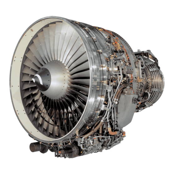
CFM56-ALL TRAINING MANUAL BASIC ENGINE PARTICULARS BASIC ENGINE EFFECTIVITY Page 23 PARTICULARS ALL CFM56 ENGINES Sep 03 BORESCOPE INSPECTION CFMI PROPRIETARY INFORMATION... - Page 25 CFM56-ALL TRAINING MANUAL CFM56 MAIN CHARACTERISTICS Combustor Section CFM56 engines consist of two independent rotating systems: (-2, -3, -5A, -5C) : Annular SAC - The low pressure system, with a rotational speed (-5B, -7B) : designated N1. Annular SAC (option DAC) - The high pressure system, with a rotational speed designated N2.
-
Page 26: Ctc-229
CFM56-ALL TRAINING MANUAL �������� ������� ������� �������� �������� �������� ��������������� CTC-229-004-00 BASIC ENGINE EFFECTIVITY Page 25 PARTICULARS ALL CFM56 ENGINES Sep 03 BORESCOPE INSPECTION CFMI PROPRIETARY INFORMATION... - Page 27 CFM56-ALL TRAINING MANUAL FAN AND BOOSTER (ALL) : Booster spool rotating air seals rub against the inner After entering the air inlet cowl, the total engine airflow shroud, and rotor blades rub against the outer shrouds. passes through fan rotor blades, which form stage 1 of Booster rotor.
- Page 28 CFM56-ALL TRAINING MANUAL ��������������� ������������������� ���� �� �� ��� ��� ��������������� ��������������������������� ���� ��� ��� FAN AND BOOSTER CTC-229-005-00 BASIC ENGINE EFFECTIVITY Page 27 PARTICULARS ALL CFM56 ENGINES Sep 03 BORESCOPE INSPECTION CFMI PROPRIETARY INFORMATION...
- Page 29 CFM56-ALL TRAINING MANUAL THE HIGH PRESSURE COMPRESSOR (HPC) (ALL) : The HPC is a 9-stage compressor mounted between the The case has internal machined circumferential slots that fan frame and the combustor case. hold the fixed vanes of stages 6, 7 and 8. The vanes are It consists of a rotor and front and rear stators.
- Page 30 CFM56-ALL TRAINING MANUAL ����� ����� ��������� ������������ ������ ������������ ����� ���������� ���� � ���� � ���� � ���� � ���� � ���� � ���� � ���� � ���� � ���� � ���� � ���� � ���� � ���� � ���� � ���� � ����� ���� � �����...
- Page 31 CFM56-ALL TRAINING MANUAL THE HIGH PRESSURE COMPRESSOR (HPC) (ALL) : Special tools. Borescope ports. Deep-well socket. There are 9 plugged borescope ports on the lower stator In case the shaft of borescope plugs S7, S8 or S9 case, at approximately the 5 o’clock position, and they are numbered S1 thru S9, where S1 is the most forward.
- Page 32 CFM56-ALL TRAINING MANUAL �� �� �� �� ��� �� ������������������� �� �� �� �������� �� ��� ��� ��� � � � ����������������� ������������ ��������� �������������������������� ������ ������������ ���������������������������������������� CTC-229-007-00 BASIC ENGINE EFFECTIVITY Page 31 PARTICULARS ALL CFM56 ENGINES Sep 03 BORESCOPE INSPECTION CFMI PROPRIETARY INFORMATION...
- Page 33 CFM56-ALL TRAINING MANUAL COMBUSTOR SECTION (ALL) : The combustor section, consisting of the combustion Single Annular Combustor (SAC). case and chamber, is located between the HPC and the LPT. The combustion chamber is housed in the combustion It produces the necessary energy to drive the turbine case and is installed between the HPC stator stage 9 and rotors.
- Page 34 CFM56-ALL TRAINING MANUAL ���������� ����������� ���� ����� ����� ����� ����������� ����������� ���������� ��������������� ������������ ���������� ����������� ������� ���������� ������������������������ CTC-229-008-00 BASIC ENGINE EFFECTIVITY Page 33 PARTICULARS ALL CFM56 ENGINES Sep 03 BORESCOPE INSPECTION CFMI PROPRIETARY INFORMATION...
- Page 35 CFM56-ALL TRAINING MANUAL COMBUSTOR SECTION (-5B, -7B) : Double Annular Combustor (DAC). The combustion case has 20 double-tip fuel nozzles The outer and inner liners are designed with panel overhangs which have closely spaced holes providing mounting pads and accommodates 3 fuel supply manifolds.
- Page 36 CFM56-ALL TRAINING MANUAL ��������������� ����������� ����������� ���������� ������������� ���� ����������� ���� ������������� ���������������������������������������������������� CTC-229-009-00 BASIC ENGINE EFFECTIVITY Page 35 PARTICULARS ALL CFM56 ENGINES Sep 03 BORESCOPE INSPECTION CFMI PROPRIETARY INFORMATION...
- Page 37 CFM56-ALL TRAINING MANUAL COMBUSTOR SECTION (ALL) : Borescope ports. There are 4 borescope ports located around the combustor case to enable inspection of the combustion chamber. The ports are numbered S12 to S15 and accommodate a simple plug with a hexagonal head. Ports S12, S13, S14 and S15 have a 10mm diameter.
- Page 38 CFM56-ALL TRAINING MANUAL �������������� ��������������� ��� ��� ����� ��� ���������� ������� ��������������� ��� ��� ������� ������� ��� ��� �������������� � � ���������������� ����������������������������������� ���������������������������������� CTC-229-010-00 BASIC ENGINE EFFECTIVITY Page 37 PARTICULARS ALL CFM56 ENGINES Sep 03 BORESCOPE INSPECTION CFMI PROPRIETARY INFORMATION...
- Page 39 CFM56-ALL TRAINING MANUAL THE HIGH PRESSURE TURBINE (HPT) & STAGE 1 LPT NOZZLE (ALL) : The HPT converts the kinetic energy of gasses from the The HPT shroud and stage 1 LPT nozzle assembly forms combustion chamber into torque to drive the HPC and it the connection between the core section and the LPT is housed in the combustion case.
- Page 40 CFM56-ALL TRAINING MANUAL ����������� ������������������ ��������� ���������� THE HPT & STAGE 1 LPT NOZZLE CTC-229-011-00 BASIC ENGINE EFFECTIVITY Page 39 PARTICULARS ALL CFM56 ENGINES Sep 03 BORESCOPE INSPECTION CFMI PROPRIETARY INFORMATION...
- Page 41 CFM56-ALL TRAINING MANUAL THE HIGH PRESSURE TURBINE (HPT) & STAGE 1 LPT NOZZLE (ALL) : (-5B, 5C, -7B) : Borescope ports. CAUTION : DO NOT MIX PLUGS S16 & S17 WITH PLUGS S12 TO S15. INSTALLING THEM IN THE WRONG PLACE MAY CAUSE ENGINE DAMAGE. The HPT section / stage 1 LPT nozzle borescope ports are located around the combustor case.
- Page 42 CFM56-ALL TRAINING MANUAL �������������� ��� ��������������� ��� ��� ��� ��� ��� ����������� �������������� ��� ��� ��� ��� ������� ������� ��� ��� ������� ������� �������� �������� ��� ��� ���� ���� ���������������������������������������� CTC-229-012-00 BASIC ENGINE EFFECTIVITY Page 41 PARTICULARS ALL CFM56 ENGINES Sep 03 BORESCOPE INSPECTION CFMI PROPRIETARY INFORMATION...
- Page 43 CFM56-ALL TRAINING MANUAL THE LOW PRESSURE TURBINE (LPT) The LPT drives the fan and booster through the LPT (-5B, -7B) : shaft. The LPT rotor/stator has: 5 ports are available to inspect the LPT. (-2, -3, -5A, -5B, -7B) : 4 stages (-5C) : 5 stages.
- Page 44 CFM56-ALL TRAINING MANUAL ����������� ������������������ ���� �� �� ��� ��� ��� ����������� ������������������ ���� ��� ��������������������������� CTC-229-013-00 BASIC ENGINE EFFECTIVITY Page 43 PARTICULARS ALL CFM56 ENGINES Sep 03 BORESCOPE INSPECTION CFMI PROPRIETARY INFORMATION...
- Page 45 CFM56-ALL TRAINING MANUAL ACCESSORY DRIVE SYSTEM (-2) : (ALL) : For maintenance tasks, the core can be turned manually At engine start, the accessory drive system transmits through a handcranking pad on left side of the TGB. external power from the engine air starter to drive the core engine.
- Page 46 CFM56-ALL TRAINING MANUAL ������������� ����� ������������ ����������� ��������������� ��������������� ������� ����������������� ���������� ����������� ����� ��������� �������� ������������� ������������� �������������������� �������������������� ����������� ����������� ���������������������� �� ����������������������� CTC-229-014-00 BASIC ENGINE EFFECTIVITY Page 45 PARTICULARS ALL CFM56 ENGINES Sep 03 BORESCOPE INSPECTION CFMI PROPRIETARY INFORMATION...
- Page 47 CFM56-ALL TRAINING MANUAL THIS PAGE INTENTIONALLY LEFT BLANK BASIC ENGINE EFFECTIVITY Page 46 PARTICULARS ALL CFM56 ENGINES Sep 03 BORESCOPE INSPECTION CFMI PROPRIETARY INFORMATION...
-
Page 48: Requirements
CFM56-ALL TRAINING MANUAL REQUIREMENTS EFFECTIVITY Page 47 REQUIREMENTS ALL CFM56 ENGINES Sep 03 BORESCOPE INSPECTION CFMI PROPRIETARY INFORMATION... - Page 49 CFM56-ALL TRAINING MANUAL BORESCOPE ACCESS LIMITATIONS (ALL) : There are two limitation factors that have to be considered when preparing for borescope inspection on CFM56 engines. These considerations are : - the size of the borescope probe to be inserted into the engine.
- Page 50 CFM56-ALL TRAINING MANUAL WITHOUT MOTORING TIME TO PORT No. ENGINE PORT SIZE WRENCH REACH AREAS VIEWED LOCATION (MM) SIZE -2/-3/-5A -5B/-5C 100°F(38°C) 200°F(93°C) BOOSTER STAGE 3 T/E STAGE 4 L/E STAGE 5 T/E HPC CASE 10 MM 1/2 HEX STAGE 1 L/E 30 mn 8 MM 1/2 HEX...
- Page 51 CFM56-ALL TRAINING MANUAL BORESCOPE ACCESS LIMITATIONS (ALL) : Probe 1 diameter limitation. To speed up the engine cool down time after shutdown, the engine starter may be used to dry motor the engine, Consult the table for port diameters where probe 1 can (Refer to the AMM).
- Page 52 CFM56-ALL TRAINING MANUAL WITHOUT MOTORING TIME TO PORT No. ENGINE PORT SIZE WRENCH REACH AREAS VIEWED LOCATION (MM) SIZE -2/-3/-5A -5B/-5C 100°F(38°C) 200°F(93°C) COMBUSTION 10 MM 1 1/4 HEX COMBUSTOR 3.5 hrs 2.0 hrs CASE HPT NOZZLE L/E & T/E 4.5 hrs 3.0 hrs 10 MM...
- Page 53 CFM56-ALL TRAINING MANUAL DOCUMENTATION (ALL) : AMM. The Aircraft Maintenace Manual (AMM) provides comprehensive instructions on how to perform a borescope inspection and provides the limits for the various engine parts. There are no definitive measurement devices for the borescope. Evaluating inconsistencies is not an easy task because all measurements by borescope are comparative.
- Page 54 CFM56-ALL TRAINING MANUAL ---------------------------------------------------------------------------------------------------------------------------------------------- INSPECT/CHECK MAXIMUM REMARKS SERVICEABLE LIMITS ---------------------------------------------------------------------------------------------------------------------------------------------- Stages 1-4 compressor blade airfoil leading and trailing edge, upper 75 percent: A.Tears Not serviceable Replace the engine Ref. TASK 71-00-00-000- 042) or repair (Ref. TASK 72-31-00-300-004). B.Nicks, missing Any number 0.04 in. (1.0 See limit extensions material and mm) max depth...
- Page 55 CFM56-ALL TRAINING MANUAL DOCUMENTATION (ALL) : NDTM. Words such as nicks, dents and scratches, for example, The records and maps will remain in the engine folder are often used in the AMM. until the damaged parts are repaired, or replaced. The NDTM (Non Destructive Test Manual) provides a Note : When defect/damage maps are used, accomplish comprehensive list and an explanation of these words in...
- Page 56 CFM56-ALL TRAINING MANUAL ��������������������������� ����� ������ ������� ���������� �������� ��������������� ����������� ���� �������� ���������� ������������������ ����������� ������������������������ �������������� �������������� ����������������������� ���������� ��������������������� ������������������� �������� ����� �������� �������������������������������� ���������������������������� �� � ������ ����������� �������������� ����������������������������� ����������������������������� ��������������������������� ������������������ ����� ������ ������� ����������...
- Page 57 CFM56-ALL TRAINING MANUAL MATERIALS AND EQUIPMENT (ALL) : Rigid borescope probe set. CFMI have designed their own light source 856A1322 and rigid borescope set 856A1320, including various probes, adapters and extensions. Optional equipment is available for cameras, computers, VCR’S, and special tools that attach to the equipment. Other borescope systems may be acceptable if they meet CFMI specifications.
- Page 58 CFM56-ALL TRAINING MANUAL ������ ������� ���������� ������� ���������� ������� ���������� ������������� ������� ������� �������� ������� ���� ������� ���������� �������� ����������� ������ ����� ��������� ���������� ����� ��������� ��������� ������� ������������ ������������������������� CTC-229-017-00 EFFECTIVITY Page 57 REQUIREMENTS ALL CFM56 ENGINES Sep 03 BORESCOPE INSPECTION CFMI PROPRIETARY INFORMATION...
- Page 59 CFM56-ALL TRAINING MANUAL MATERIALS AND EQUIPMENT (ALL) : Rigid borescope probe set. There are 4 rigid borescope probes for inspection of the internal areas of the engine and each probe is used for a specific purpose : - Probe 1 (black) : Magnification, close inspection, detailed evaluation and confirmation of defects (cannot be used in every hole due to its diameter).
- Page 60 CFM56-ALL TRAINING MANUAL ������ ����������������������������� ����������������������� ����� � � � � ����������� ���������� ���������� ������������� ��������������� ����������� ��������� ��������� ������ � � �������� �������� �������� �������� � � ��������������� ������ ����� ����� ����� � ���������������� ���� ���� ���� ���� � �...
- Page 61 CFM56-ALL TRAINING MANUAL MATERIALS AND EQUIPMENT (ALL) : Flexible probe set. Flexible borescope set 856A1321 and guide tube 856A1310 (blue) or 856A1351 (red), are designed to be used on CFM56 engines and meet CFMI specifications. (-5B, -7B) : Guide tube 856A1702 (red) is used for DAC engines. (ALL) : Optional equipment is available for cameras, computers, VCR’S, and special tools that attach to the borescope...
- Page 62 CFM56-ALL TRAINING MANUAL ������� ���������� ������� ������ ������� ������������������ ��������������������� ������������ ���������������� �������������� ��������� ������������ ����������������� ���������� ���������������������������� CTC-229-019-00 EFFECTIVITY Page 61 REQUIREMENTS ALL CFM56 ENGINES Sep 03 BORESCOPE INSPECTION CFMI PROPRIETARY INFORMATION...
- Page 63 CFM56-ALL TRAINING MANUAL EQUIPMENT CHECKS (ALL) : The borescope resolution monitor. Before starting any inspection inside the engine, the inspector should ensure that the viewing definition of the rigid and flexible borescope probes is as precise as possible. Borescope resolution monitor 856A1323 allows both rigid and flexible probes to be checked against a calibrated display.
- Page 64 CFM56-ALL TRAINING MANUAL LIGHT BUNDLE RESOLUTION TARGET CLAMPING DEVICE BORESCOPE LENS BORESCOPE RESOLUTION MONITOR CTC-229-020-00 EFFECTIVITY Page 63 REQUIREMENTS ALL CFM56 ENGINES Sep 03 BORESCOPE INSPECTION CFMI PROPRIETARY INFORMATION...
- Page 65 CFM56-ALL TRAINING MANUAL EQUIPMENT CHECKS (ALL) : The resolution target. Rigid probes. The resolution target is divided into group and element For rigid probes with a 1:1 magnification at 2in., the numbers, which gradually diminish in size towards the 6 individual lines (3 vertical and 3 horizontal) of group 3, center of the display.
- Page 66 CFM56-ALL TRAINING MANUAL � � ������ ������ ������� ��������� � � � � � � � � � � � � � � � � � � � � � � � � � � � � � � � �...
- Page 67 CFM56-ALL TRAINING MANUAL CORE ENGINE ROTATION (ALL) : (-5A, -5B, -5C) : Manual method: Two pads on the accessory gearbox (AGB) are used to rotate the core engine: - Insert a 3⁄4 inch square drive socket attached to a 2ft. long breaker bar into the handcranking drive pad.
- Page 68 CFM56-ALL TRAINING MANUAL �� ����������� ��� ����������� ������ ����������� ������� ������������ ��������� ����������� ������������ ������������� ��� �� ��� ��� ������������� CTC-229-022-00 EFFECTIVITY Page 67 REQUIREMENTS ALL CFM56 ENGINES Sep 03 BORESCOPE INSPECTION CFMI PROPRIETARY INFORMATION...
- Page 69 CFM56-ALL TRAINING MANUAL CORE ENGINE ROTATION (ALL) : Air drive method: The N2 rotor can also be turned with a pneumatic motor. Install the pneumatic motor assembly on the pad. (-2) : The direction of rotation and speed of the core engine Pneumatic motor 856A1142 is installed on the rotor can be selected through a hand, or foot control handcranking pad on the left side of the TGB.
- Page 70 CFM56-ALL TRAINING MANUAL ������� �� �� �������� �������� ������� ������������� �������� �������� ��� ������������������������ CTC-229-023-00 EFFECTIVITY Page 69 REQUIREMENTS ALL CFM56 ENGINES Sep 03 BORESCOPE INSPECTION CFMI PROPRIETARY INFORMATION...
- Page 71 CFM56-ALL TRAINING MANUAL CORE ENGINE ROTATION (ALL) : Another way of turning the core is through Electronic Turning Tool (ETT) Sweeney, P/N 18946, which adapts on the same pad as the pneumatic motor. ETT method: Install the plate adapter, drive shaft and ETT motor assembly on the adequate pad, with a QAD clamp.
- Page 72 CFM56-ALL TRAINING MANUAL ��������� ����� ��������� ���� ���� ���������� ������������� �������� ���� ����������������������� CTC-229-024-00 EFFECTIVITY Page 71 REQUIREMENTS ALL CFM56 ENGINES Sep 03 BORESCOPE INSPECTION CFMI PROPRIETARY INFORMATION...
- Page 73 CFM56-ALL TRAINING MANUAL THIS PAGE INTENTIONALLY LEFT BLANK EFFECTIVITY Page 72 REQUIREMENTS ALL CFM56 ENGINES Sep 03 BORESCOPE INSPECTION CFMI PROPRIETARY INFORMATION...
-
Page 74: Inspection Of Fan And Booster
CFM56-ALL TRAINING MANUAL INSPECTION OF FAN AND BOOSTER FAN AND EFFECTIVITY Page 73 BOOSTER ALL CFM56 ENGINES Sep 03 BORESCOPE CFMI PROPRIETARY INFORMATION INSPECTION... - Page 75 CFM56-ALL TRAINING MANUAL FAN AND BOOSTER (ALL) : N1 rotor indexing. Setting a reference angular position for the rotor provides an easy method to return quickly and accurately to a defect found earlier. The following procedure enables the reference point for the N1 rotor to be obtained.
- Page 76 CFM56-ALL TRAINING MANUAL �������������� ���������� ����������������� CTC-229-025-00 FAN AND EFFECTIVITY Page 75 BOOSTER ALL CFM56 ENGINES Sep 03 BORESCOPE CFMI PROPRIETARY INFORMATION INSPECTION...
- Page 77 CFM56-ALL TRAINING MANUAL FAN AND BOOSTER (ALL) : Visual inspection of the fan blades is performed on a regular basis depending on the MRB, or MPD. If defects are found, then an unscheduled inspection is required. Possible defects: - missing material, tip curl. - nicks, dents, pits or scratches, usually due to ingestion of small foreign objects such as sand, stones, dust, tarmac, etc.
- Page 78 CFM56-ALL TRAINING MANUAL ������� ������ ���� ���� ����� ���������� �������� ���� ������� ���� ������� ����������� �������� �������������� �������������������������������������� CTC-229-026-00 FAN AND EFFECTIVITY Page 77 BOOSTER ALL CFM56 ENGINES Sep 03 BORESCOPE CFMI PROPRIETARY INFORMATION INSPECTION...
- Page 79 CFM56-ALL TRAINING MANUAL FAN AND BOOSTER (ALL) : Visual inspection of the outlet guide vanes (OGV) is performed on a regular basis depending on the MRB, or MPD. If defects are found, then an unscheduled inspection is required. Possible defects: - missing material.
- Page 80 CFM56-ALL TRAINING MANUAL ����� ���������� ���� ������������ �������� ���� ���� ����������������� ��������� ���������������������������������� CTC-229-064-00 FAN AND EFFECTIVITY Page 79 BOOSTER ALL CFM56 ENGINES Sep 03 BORESCOPE CFMI PROPRIETARY INFORMATION INSPECTION...
- Page 81 CFM56-ALL TRAINING MANUAL FAN AND BOOSTER (ALL) : Rigid probe No 2 (yellow), installed on a long right angle adapter, can be used to reach the front of the splitter fairing area in order to inspect the booster. From this position the following are visible: - Stator vane stage 1 - Rotor stage 2 leading edge through stator stage 1.
- Page 82 CFM56-ALL TRAINING MANUAL ���� ������������������������������������������ ����������� ��������� ������������ � � ����������� � ����� ����������������������������������� CTC-229-027-00 FAN AND EFFECTIVITY Page 81 BOOSTER ALL CFM56 ENGINES Sep 03 BORESCOPE CFMI PROPRIETARY INFORMATION INSPECTION...
- Page 83 CFM56-ALL TRAINING MANUAL FAN AND BOOSTER (-2, -3, -5A, -7B) : To inspect the booster, unplugged borescope port S0 can be accessed with a probe installed on a long right angle adapter. (-5B, -5C) : To inspect the booster, unplugged borescope port S03 can be accessed with a probe installed on a long right angle adapter.
- Page 84 CFM56-ALL TRAINING MANUAL ���� ������������������������������������������ ����������� ��������� ������������ ������������� � � � ������������������������������������������ CTC-229-028-00 FAN AND EFFECTIVITY Page 83 BOOSTER ALL CFM56 ENGINES Sep 03 BORESCOPE CFMI PROPRIETARY INFORMATION INSPECTION...
- Page 85 CFM56-ALL TRAINING MANUAL FAN AND BOOSTER (-5B, -5C) : After inspection through port S03, continue inspection of the booster through port S05, using probe No 2 (yellow), installed on a long right angle adapter. Port S05 is located at approximately 4 o’clock. Insert the borescope probe into the port and go through the 2 cases to reach the inspection area.
- Page 86 CFM56-ALL TRAINING MANUAL ������������ ���� �������� ����������� ��������� ������������������������������������������ � � � � ������������������������������������������������������ CTC-229-029-00 FAN AND EFFECTIVITY Page 85 BOOSTER ALL CFM56 ENGINES Sep 03 BORESCOPE CFMI PROPRIETARY INFORMATION INSPECTION...
- Page 87 CFM56-ALL TRAINING MANUAL FAN AND BOOSTER (ALL) : Area E : Booster rotor damage may occur after the engine - This area of the blade starts from the top of the experienced an abnormal problem. The following list platform and extends toward the blade tip for provides examples of conditions where a complete approximately 10 mm.
- Page 88 CFM56-ALL TRAINING MANUAL ����� ��� ������������������ � ����� ����������������� ������������� �������� ���� ������� � ���� ����� ���������� ����� �������� ������������������������������ CTC-229-030-00 FAN AND EFFECTIVITY Page 87 BOOSTER ALL CFM56 ENGINES Sep 03 BORESCOPE CFMI PROPRIETARY INFORMATION INSPECTION...
- Page 89 CFM56-ALL TRAINING MANUAL FAN AND BOOSTER (ALL) : During an inspection of the booster, any defects should be assessed against the serviceability limits in the Aircraft Maintenance Manual. Possible defects: - Cracks or tears. - Nicks and scratches. - Dents. - Erosion.
- Page 90 CFM56-ALL TRAINING MANUAL ���� ������� ������� �������� ��� ���� ���������� ����� ����� ���� ������� ���� ������������������������������ CTC-229-031-00 FAN AND EFFECTIVITY Page 89 BOOSTER ALL CFM56 ENGINES Sep 03 BORESCOPE CFMI PROPRIETARY INFORMATION INSPECTION...
- Page 91 CFM56-ALL TRAINING MANUAL THIS PAGE INTENTIONALLY LEFT BLANK FAN AND EFFECTIVITY Page 90 BOOSTER ALL CFM56 ENGINES Sep 03 BORESCOPE CFMI PROPRIETARY INFORMATION INSPECTION...
-
Page 92: Inspection Of High Pressure Compressor
CFM56-ALL TRAINING MANUAL INSPECTION OF HIGH PRESSURE COMPRESSOR HIGH PRESSURE EFFECTIVITY Page 91 COMPRESSOR ALL CFM56 ENGINES Sep 03 BORESCOPE CFMI PROPRIETARY INFORMATION INSPECTION... - Page 93 CFM56-ALL TRAINING MANUAL HIGH PRESSURE COMPRESSOR (HPC) (ALL) : General inspection method. HPC rotor blade damage may occur after the engine experienced an abnormal operating problem. The To inspect the blades, it is necessary to open the VSV’s. following list provides examples of conditions where Refer to the appropriate procedure in the AMM.
- Page 94 CFM56-ALL TRAINING MANUAL �� �� �� �� �� �� �� �� ��� � ������������������ ������������� ������������������������������ ������������������������������ ������������������������� �������� �������������� CTC-229-032-00 HIGH PRESSURE EFFECTIVITY Page 93 COMPRESSOR ALL CFM56 ENGINES Sep 03 BORESCOPE CFMI PROPRIETARY INFORMATION INSPECTION...
- Page 95 CFM56-ALL TRAINING MANUAL N2 ROTOR INDEXING (ALL) : Stage 4 of the High Pressure Compressor is the first 5. The next blade is blade No 1. Position the leading stage where the blades are retained in position with blade edge of blade No 1 in line with the leading edge of locks.
- Page 96 CFM56-ALL TRAINING MANUAL ������������� �������������� ����������������� ���������������� ������� ������� ���������� ������������ �������� ���������������� ���������� ����������������� ����������������� ����������������� ������� ����������������� ��������������� ������������������ ������������������� ����������������� CTC-229-033-00 HIGH PRESSURE EFFECTIVITY Page 95 COMPRESSOR ALL CFM56 ENGINES Sep 03 BORESCOPE CFMI PROPRIETARY INFORMATION INSPECTION...
- Page 97 CFM56-ALL TRAINING MANUAL HIGH PRESSURE COMPRESSOR (HPC) Inspection areas: - The outer third of the rotor blade tip area and the anti-erosion hard coating on the concave side. - The squealer tips. - The stage 1 blade stiffener near the tip of the blade. - The blade locks on stages 4 to 9, which maintain the blades in the circumferential slots.
- Page 98 CFM56-ALL TRAINING MANUAL ��� ����� ��������� �������������� ����������������� ����������������� ������������� ������������ ������������� ������� �������������� ����������� �������������������� CTC-229-034-00 HIGH PRESSURE EFFECTIVITY Page 97 COMPRESSOR ALL CFM56 ENGINES Sep 03 BORESCOPE CFMI PROPRIETARY INFORMATION INSPECTION...
- Page 99 CFM56-ALL TRAINING MANUAL HIGH PRESSURE COMPRESSOR (HPC) (ALL) : Refer to the AMM for the precise dimensions of the Rotor blades specific inspection areas. following critical areas: HPC rotor blade stages are all different. The lower area of the airfoil. This is the airfoil root radius area, plus the area From stage 1 to stage 9, they become smaller and are which extends toward the blade tip over approximately...
- Page 100 CFM56-ALL TRAINING MANUAL ������������ ��������������� ������������� ��������������� � ����� ��������� � ������ ����� ������ ��������� ������ ���������� ������������ ������ ���������� ���������� ���������� ����� ������� �������� ������������������� �������� �������������������������� CTC-229-035-00 HIGH PRESSURE EFFECTIVITY Page 99 COMPRESSOR ALL CFM56 ENGINES Sep 03 BORESCOPE CFMI PROPRIETARY INFORMATION INSPECTION...
- Page 101 CFM56-ALL TRAINING MANUAL HIGH PRESSURE COMPRESSOR (HPC) (ALL) : Possible defects: When the HPC blades are inspected, the following defects should be evaluated with the AMM serviceability limits : - Cracks, or tears. - Nicks and scratches. - Dents. - Erosion. - Tip curl.
- Page 102 CFM56-ALL TRAINING MANUAL ���� ������� �������� ������� ��� ���� ������� ���� �������� ���������� ���� ���� �������� ������� ���� ���� ���� ������� ���� ����� �������������������������� CTC-229-036-00 HIGH PRESSURE EFFECTIVITY Page 101 COMPRESSOR ALL CFM56 ENGINES Sep 03 BORESCOPE CFMI PROPRIETARY INFORMATION INSPECTION...
- Page 103 CFM56-ALL TRAINING MANUAL THIS PAGE INTENTIONALLY LEFT BLANK HIGH PRESSURE EFFECTIVITY Page 102 COMPRESSOR ALL CFM56 ENGINES Sep 03 BORESCOPE CFMI PROPRIETARY INFORMATION INSPECTION...
-
Page 104: Inspection Of Combustor Section
CFM56-ALL TRAINING MANUAL INSPECTION OF COMBUSTOR SECTION COMBUSTION EFFECTIVITY Page 103 CHAMBER ALL CFM56 ENGINES Sep 03 BORESCOPE CFMI PROPRIETARY INFORMATION INSPECTION... - Page 105 CFM56-ALL TRAINING MANUAL COMBUSTION SECTION (ALL) : Single Annular Combustor (SAC). The combustor is inspected through ports S12, S13, S14, Probe 1 (black, hi-mag) is recommended for viewing the S15 and igniter ports S10 and S11, using probes 1, 2, 3 aft end of the inner and outer liners.
- Page 106 CFM56-ALL TRAINING MANUAL ������������ ���������������������������� ���������������������������������������������� ������������������������������������������������������������ ���������������������������� ��������������������������� ����������������������������������� CTC-229-038-00 COMBUSTION EFFECTIVITY Page 105 CHAMBER ALL CFM56 ENGINES Sep 03 BORESCOPE CFMI PROPRIETARY INFORMATION INSPECTION...
- Page 107 CFM56-ALL TRAINING MANUAL COMBUSTION SECTION (ALL) : Inspection of SAC inner liner. Borescope inspection of the combustion section may be required for a visual assessment as part of the on- The inner liner has a dome band and 4 panels. condition maintenance plan.
- Page 108 CFM56-ALL TRAINING MANUAL ����������� � � � � � ������ � � � � ����������� ����������� ����� ����� ������������������� ������� ������� ������� ������� ������� ���� ���� ������� ������� ���� ������� ������� ���� ��������������������������������������������������������������� CTC-229-039-00 COMBUSTION EFFECTIVITY Page 107 CHAMBER ALL CFM56 ENGINES Sep 03 BORESCOPE CFMI PROPRIETARY INFORMATION...
- Page 109 CFM56-ALL TRAINING MANUAL COMBUSTION SECTION (ALL) : Possible defects on SAC liners. Carbon deposits are often misinterpreted as defects (holes, burn-through, cracks, etc.). Use the high magnification probe, and higher light intensity to confirm the type of defect. The aft panel of the inner liner is prone to distortion and cracking.
- Page 110 CFM56-ALL TRAINING MANUAL ������������ ������������ ����� �������� ���� ������� ������ �� ������ ����� ������� ���� ������� �������� �������� ������ ����� ������ ���������� ��� � ��� ��������������� ����� ����� ����� ����� ����� ������ � � � ������ ���� ����� ����� �� ������ ����...
- Page 111 CFM56-ALL TRAINING MANUAL COMBUSTION SECTION (ALL) : Inspection of the SAC dome area. The following areas of the combustion chamber also need to be inspected: - Fuel nozzle tips. - Fuel nozzle stems outside the combustor dome. - Sleeves with 2 concentric swirlers. - Deflectors.
- Page 112 CFM56-ALL TRAINING MANUAL ��������� ��������������� ������������ � ������������ ����� ���������� ���� ��������� ������ ��������� ������ �� ���� ���� ������������� ������������ ������ ����������� ���������� ��� ����� ���� ��������� ������������ ������ ��� �������������������������������������������������� CTC-229-041-00 COMBUSTION EFFECTIVITY Page 111 CHAMBER ALL CFM56 ENGINES Sep 03 BORESCOPE CFMI PROPRIETARY INFORMATION...
- Page 113 CFM56-ALL TRAINING MANUAL COMBUSTION SECTION (ALL) : Possible defects in the SAC dome area. The following defects should be assessed with the AMM serviceability limits : - Cracks, or tears. - Erosion. - Distortion of internal parts. - Missing material. - Dirt buildup.
- Page 114 CFM56-ALL TRAINING MANUAL ������ ������ ��������� ��������������� ������ ������ ������ ������ ����� �������� ������ ������ ��������������� ������ �������� �������� ������� �������� ������ �������� ������������ ���� ����������������������������������������� CTC-229-042-00 COMBUSTION EFFECTIVITY Page 113 CHAMBER ALL CFM56 ENGINES Sep 03 BORESCOPE CFMI PROPRIETARY INFORMATION INSPECTION...
- Page 115 CFM56-ALL TRAINING MANUAL COMBUSTION SECTION Inspection of SAC chamber after birdstrike/FOD. Insert a rigid probe into the left igniter position and examine the position of the fuel nozzle tips in relation to the bore of the inner and outer ferrules to make sure they are in the bore of the ferrules.
- Page 116 CFM56-ALL TRAINING MANUAL ������ ������������������� ������������������ ���������������� ������������ ��������������������� ��������������������� ��������������������������������� CTC-229-065-00 COMBUSTION EFFECTIVITY Page 115 CHAMBER ALL CFM56 ENGINES Sep 03 BORESCOPE CFMI PROPRIETARY INFORMATION INSPECTION...
- Page 117 CFM56-ALL TRAINING MANUAL COMBUSTION SECTION (-5B, -7B) : Double Annular Combustor (DAC). Probe 1 (black) is recommended for viewing the aft ends of the inner and outer liners. It is also used for evaluating defects that were found when using probes 2, 3, or 4. The combustor is inspected through ports S12, S13, S14, S14.5, S15 and igniter ports S10 and S11.
- Page 118 CFM56-ALL TRAINING MANUAL ����������� ������������������������� ������������� �������� ����� ���������������������������������������������� ������������������������������������������������������������ ���������������������������� ��������������������������� ����������������������������������� CTC-229-043-00 COMBUSTION EFFECTIVITY Page 117 CHAMBER ALL CFM56 ENGINES Sep 03 BORESCOPE CFMI PROPRIETARY INFORMATION INSPECTION...
- Page 119 CFM56-ALL TRAINING MANUAL COMBUSTION SECTION (-5B, -7B) : Inspection of DAC outer liner. The outer liner has a dome band and 4 panels. Panel 1 features 2 igniter holes (with ferrules), and small dilution holes. Panel 2 features 5 borescope holes and 2 small dilution holes near the igniters.
- Page 120 CFM56-ALL TRAINING MANUAL ����������� � � � ���� � ���� ������ ���������� � � � ������������ � ����������� ����������� ����� ����� ���� ���� ������������������� �������������� ����� ������� ������� ������� ������� ���� ������� ������� ���� ������� ������� ���� ���� ��������������������������������������������������������������� CTC-229-044-00 COMBUSTION EFFECTIVITY Page 119...
- Page 121 CFM56-ALL TRAINING MANUAL COMBUSTION SECTION (-5B, -7B) : Inspection of DAC dome area. The following areas of the combustion chamber also need to be inspected: - Fuel nozzle tips. - Fuel nozzle stems outside the combustor dome. - Spectacle plate and inner and outer deflectors. - Inner and outer liners.
- Page 122 CFM56-ALL TRAINING MANUAL ����������� ������� ������� ��������������� ������������� � ���������� ��������������� �� ����� ���� ������� ����������� ��������������� ������������� ����� ������� ��������������� �������������������������������������������������� CTC-229-045-00 COMBUSTION EFFECTIVITY Page 121 CHAMBER ALL CFM56 ENGINES Sep 03 BORESCOPE CFMI PROPRIETARY INFORMATION INSPECTION...
- Page 123 CFM56-ALL TRAINING MANUAL COMBUSTION SECTION (-5B, -7B) : Possible defects in the DAC dome area. Possible defects on the DAC outer and inner liners. Whenever the combustion chamber is inspected, the Carbon deposits are often misinterpreted as defects following defects should be assessed with the AMM (holes, burn-through, cracks, etc.).
- Page 124 CFM56-ALL TRAINING MANUAL ���������������� ����������� ������ ��������� ������ ������� ���� ����� ����� ���� ��������������� ���������� ������� ����� ���� ����������� ����� ������ ���� � � � � ���� ����� ������ �������� ����� ������������ ��������� ���� ������ ��������������� ����� ���� � � �...
- Page 125 CFM56-ALL TRAINING MANUAL COMBUSTION SECTION (-5B, -7B) : Inspection of DAC chamber after birdstrike/FOD. Insert a rigid probe into the left igniter position and examine the position of the fuel nozzle tips in relation to the bore of the inner and outer ferrules to make sure they are in the bore of the ferrules.
- Page 126 CFM56-ALL TRAINING MANUAL ������ ������������������� ������������������ ������� ����������� ������������ ���������������� ��������������������� ��������������������� ��������������������������������� CTC-229-047-00 COMBUSTION EFFECTIVITY Page 125 CHAMBER ALL CFM56 ENGINES Sep 03 BORESCOPE CFMI PROPRIETARY INFORMATION INSPECTION...
- Page 127 CFM56-ALL TRAINING MANUAL THIS PAGE INTENTIONALLY LEFT BLANK COMBUSTION EFFECTIVITY Page 126 CHAMBER ALL CFM56 ENGINES Sep 03 BORESCOPE CFMI PROPRIETARY INFORMATION INSPECTION...
-
Page 128: Inspection Of High Pressure Turbine
CFM56-ALL TRAINING MANUAL INSPECTION OF HIGH PRESSURE TURBINE HIGH PRESSURE EFFECTIVITY Page 127 TURBINE ALL CFM56 ENGINES Sep 03 BORESCOPE CFMI PROPRIETARY INFORMATION INSPECTION... - Page 129 CFM56-ALL TRAINING MANUAL HIGH PRESSURE TURBINE (HPT) (ALL) : Inspection with rigid probe. Inspect the HPT nozzles through ports S13 and S15. Use probe No 1 (black, high magnification) to inspect the nozzle segments. The high intensity light source is used to accurately inspect the nozzles.
- Page 130 CFM56-ALL TRAINING MANUAL ������������ �������������� ������������ ����������������� ����� ��������������� �������������������� ����� ���������� ����� �������� �������������������������������������� CTC-229-048-00 HIGH PRESSURE EFFECTIVITY Page 129 TURBINE ALL CFM56 ENGINES Sep 03 BORESCOPE CFMI PROPRIETARY INFORMATION INSPECTION...
- Page 131 CFM56-ALL TRAINING MANUAL HIGH PRESSURE TURBINE (HPT) (ALL) : Inspection with flexible probe. Carefully push the flexible probe into the guide tube to Use the flexible probe with a guide tube to inspect the HPT nozzle segments on the convex sides, the trailing inspect the next HPT nozzle segment.
- Page 132 CFM56-ALL TRAINING MANUAL ��������� ������������ ���� ���������� ������������ ����� ���������� ��������������������������� � �������������� ��������� ���� ������ �������� ������ �������� ���������� ���������� ���������� ����������������������������������������� CTC-229-049-00 HIGH PRESSURE EFFECTIVITY Page 131 TURBINE ALL CFM56 ENGINES Sep 03 BORESCOPE CFMI PROPRIETARY INFORMATION INSPECTION...
- Page 133 CFM56-ALL TRAINING MANUAL HIGH PRESSURE TURBINE (HPT) (ALL) : Inspection of the HPT nozzle is usually carried out in conjunction with the combustion chamber inspection. HPT nozzle inspection areas. The HPT nozzle vanes are cast shells and internally divided into forward and aft cooling compartments. CDP cooling air enters the vane compartments through the inner and outer ends of the vanes and exits through holes in the vanes’s leading edge and slots in the trailing...
- Page 134 CFM56-ALL TRAINING MANUAL ���� ������� ����������������������� ����� ����� �������������� ���� ����� �������������� ������������ ���� ������������� ������������������� �������������� ����������� �������������������������������������� CTC-229-050-00 HIGH PRESSURE EFFECTIVITY Page 133 TURBINE ALL CFM56 ENGINES Sep 03 BORESCOPE CFMI PROPRIETARY INFORMATION INSPECTION...
- Page 135 CFM56-ALL TRAINING MANUAL HIGH PRESSURE TURBINE (HPT) (ALL) : Possible defects. Leading edge damage : - cracks. Whenever the HPT nozzle is inspected, the following - burns and/or bulges. - blocked cooling air passages. defects should be assessed with the AMM serviceability limits: Concave and convex surfaces : - Discoloration (anywhere).
- Page 136 CFM56-ALL TRAINING MANUAL ������������� ������������ ������� ����� �������� ������� �������� ������������ ���� ������������� �������� ������������������� ������������������ �������� ������������� ������� ����������� ������� ����� ���� �������� ��������������������������� CTC-229-051-00 HIGH PRESSURE EFFECTIVITY Page 135 TURBINE ALL CFM56 ENGINES Sep 03 BORESCOPE CFMI PROPRIETARY INFORMATION INSPECTION...
- Page 137 CFM56-ALL TRAINING MANUAL HIGH PRESSURE TURBINE (HPT) (ALL) : Inspection with a rigid probe. (-2, -3, -5A) : Inspect the HPT rotor blade T/E and the rear portion of the HPT shroud, through ports S17 and S18. (-5B, -5C, -7B) : Inspect the HPT rotor blade T/E and the rear portion of the HPT shroud, through ports S16 and S17.
- Page 138 CFM56-ALL TRAINING MANUAL ������������ ���������� ����������� �������������� �������� �������� ������������� ����������� ���������������������������������� ������������������������������������ ������������������������������������ ������������������������������ ����������������������������������������������������������� CTC-229-052-00 HIGH PRESSURE EFFECTIVITY Page 137 TURBINE ALL CFM56 ENGINES Sep 03 BORESCOPE CFMI PROPRIETARY INFORMATION INSPECTION...
- Page 139 CFM56-ALL TRAINING MANUAL HIGH PRESSURE TURBINE (HPT) (ALL) : Inspection with a flexible probe. Use the flexible probe with the guide tube to inspect the HPT blade L/E and the forward part of the HPT shroud. Insert the guide tube 856A1310, or 856A1351, through the S10, or S11 ports and position it between two nozzle vanes.
- Page 140 CFM56-ALL TRAINING MANUAL ������������ ������������ ���� ���������� ������������ ����� ���������������������������� ����������������������������� ������������������������ ��������������������������� ���������� �������� � �������������� �������� � �������������� �������������������� �������� � �������������� ������������������ ������������������ �������������� ������������������ ����������� ���������� ������� ���� �������� ������� �������������������������������������������������������������� CTC-229-053-00 HIGH PRESSURE EFFECTIVITY Page 139 TURBINE ALL CFM56 ENGINES Sep 03...
- Page 141 CFM56-ALL TRAINING MANUAL HIGH PRESSURE TURBINE (HPT) (ALL) : (ALL) : HPT rotor damage may occur after engine abnormal Individual replaceable shroud segments face the blade operation. tips and are cooled with CDP air. They can be checked during inspection of the HPT rotor leading edge and nozzle guide vane trailing edge.
- Page 142 CFM56-ALL TRAINING MANUAL � ������������� ���� ���� ���� ��������������� � ����� ������ ��������� ���� ���� � � ����� � � � � � � ������� ������ ��������� �������� ������������ ������ ���������� ���������������������������������� ������������������������������� �������� ��������� �������������������������� CTC-229-054-00 HIGH PRESSURE EFFECTIVITY Page 141 TURBINE ALL CFM56 ENGINES...
- Page 143 CFM56-ALL TRAINING MANUAL HIGH PRESSURE TURBINE (HPT) (ALL) : Specific rotor blades inspection areas. Specific inspection areas for the HPT blades are defined as follows: Area C : - All around the blade, extending from the first T/E slot just above the root fillet, toward the tip of the blade, up to the sixth T/E slot.
- Page 144 CFM56-ALL TRAINING MANUAL ���� ���� ���������������������������� � ������ ��� ���� ��� ������� ����� � ������ ����������� ���� ���������� ������� � ������ ���� ��������� ����� ������ ������� ����� ���������������������������������� CTC-229-055-00 HIGH PRESSURE EFFECTIVITY Page 143 TURBINE ALL CFM56 ENGINES Sep 03 BORESCOPE CFMI PROPRIETARY INFORMATION INSPECTION...
- Page 145 CFM56-ALL TRAINING MANUAL HIGH PRESSURE TURBINE (HPT) (ALL) : Possible defects. The following defects may be observed and should be assessed with the serviceability limits in the AMM. Trailing edge : - cracks. Tip area : - cracks. - bent, curled, or missing pieces. - tip trailing edge wear.
- Page 146 CFM56-ALL TRAINING MANUAL ������������� ������� �������� �������� ���� ������� ���� ������������ ��������� ���� ����� ������������� ����������� ��������� ������� �������� ��������� ����� ��� ����� ���� ������� ����� HPT ROTOR BLADE POSSIBLE DEFECTS CTC-229-056-00 HIGH PRESSURE EFFECTIVITY Page 145 TURBINE ALL CFM56 ENGINES Sep 03 BORESCOPE CFMI PROPRIETARY INFORMATION...
- Page 147 CFM56-ALL TRAINING MANUAL THIS PAGE INTENTIONALLY LEFT BLANK HIGH PRESSURE EFFECTIVITY Page 146 TURBINE ALL CFM56 ENGINES Sep 03 BORESCOPE CFMI PROPRIETARY INFORMATION INSPECTION...
-
Page 148: Inspection Of Low Pressure Turbine
CFM56-ALL TRAINING MANUAL INSPECTION OF LOW PRESSURE TURBINE LOW PRESSURE EFFECTIVITY Page 147 TURBINE ALL CFM56 ENGINES Sep 03 BORESCOPE CFMI PROPRIETARY INFORMATION INSPECTION... - Page 149 CFM56-ALL TRAINING MANUAL LOW PRESSURE TURBINE (LPT) (ALL) : (-2, -3, -5A, -5B, -7B) : Stage 2 thru 4 blades. The LPT features long span blades. Moving the probe in and out enables a full-length inspection, which always (-5C) : starts at the blade platform.
- Page 150 CFM56-ALL TRAINING MANUAL ������������������������ ���������������� � � � ���������������������������������� �������������� ������������������������������������ ��������������� ������������������������������������ ������������������� ������������������������������ ������������������������������� CTC-229-057-00 LOW PRESSURE EFFECTIVITY Page 149 TURBINE ALL CFM56 ENGINES Sep 03 BORESCOPE CFMI PROPRIETARY INFORMATION INSPECTION...
- Page 151 CFM56-ALL TRAINING MANUAL LOW PRESSURE TURBINE (LPT) (ALL) : Inspection areas. LPT rotor blade damage may occur after the engine experienced an abnormal operating condition. The On the LPT blades, there are 2 specific areas which are following list provides examples of the conditions where dimensionally defined through section letters: a complete LPT borescope inspection should be Area E (tip of the blade):...
- Page 152 CFM56-ALL TRAINING MANUAL ���� ����� ��������� ������ � ����� ������� ���� �������� ���� � ����� �������������������������� CTC-229-058-00 LOW PRESSURE EFFECTIVITY Page 151 TURBINE ALL CFM56 ENGINES Sep 03 BORESCOPE CFMI PROPRIETARY INFORMATION INSPECTION...
- Page 153 CFM56-ALL TRAINING MANUAL LOW PRESSURE TURBINE (LPT) (ALL) : Possible defects. Whenever the LPT blades are inspected, the following defects should be assessed against the AMM serviceability limits : - Cracks in the airfoil surface, platform, or tip shroud. - Convex and/or concave surfaces nicks and dents. - Leading edge distortion and melting, due to overtemperature.
- Page 154 CFM56-ALL TRAINING MANUAL �������� ���� ������ �������� ������� ���� ���� ���� ���� ������� ���������� �������� ������������� ��������������� ����� ������ ���� �������� �������� ��������������������������� CTC-229-059-00 LOW PRESSURE EFFECTIVITY Page 153 TURBINE ALL CFM56 ENGINES Sep 03 BORESCOPE CFMI PROPRIETARY INFORMATION INSPECTION...
- Page 155 CFM56-ALL TRAINING MANUAL LOW PRESSURE TURBINE (LPT) (ALL) : Possible defects on last stage blades. In addition to the regular defects previously described, the following can also be found on the last stage blades: - No more axial preload on the tip shroud assembly. - Tip shroud interlock wear.
- Page 156 CFM56-ALL TRAINING MANUAL �������������� ��������� ��������������������� ������������ ��������� �������� ������������ �������������� ������������ ����������� �������������� � � � � ��������� ����� � ����� ����� � ������������ ��������� ������ ������������������������������������������������ CTC-229-060-00 LOW PRESSURE EFFECTIVITY Page 155 TURBINE ALL CFM56 ENGINES Sep 03 BORESCOPE CFMI PROPRIETARY INFORMATION INSPECTION...
- Page 157 CFM56-ALL TRAINING MANUAL THIS PAGE INTENTIONALLY LEFT BLANK LOW PRESSURE EFFECTIVITY Page 156 TURBINE ALL CFM56 ENGINES Sep 03 BORESCOPE CFMI PROPRIETARY INFORMATION INSPECTION...
-
Page 158: Appendix : Number Of Blades Per Rotor
CFM56-ALL TRAINING MANUAL APPENDIX : NUMBER OF BLADES PER ROTOR APPENDIX EFFECTIVITY Page 157 BORESCOPE ALL CFM56 ENGINES Sep 03 INSPECTION CFMI PROPRIETARY INFORMATION... - Page 159 CFM56-ALL TRAINING MANUAL BLADE QUANTITIES Here is a table giving the quantity of blades on the following rotors, for each engine model: - The fan and booster rotor, where Stage 1 is the fan rotor itself - The high pressure compressor rotor - The high pressure turbine rotor - The low pressure turbine rotor.
- Page 160 CFM56-ALL TRAINING MANUAL FAN & BOOSTER HP COMPRESSOR LP TURBINE ENGINE TURBINE MODEL ST5 ST6 CFM56-2 162 157 160 CFM56-3 162 157 160 CFM56-5A 150 150 134 CFM56-5B 150 150 134 CFM56-5C 144 138 146 CFM56-7B 150 150 134 APPENDIX EFFECTIVITY Page 159 BORESCOPE...
- Page 161 CFM56-ALL TRAINING MANUAL THIS PAGE INTENTIONALLY LEFT BLANK APPENDIX EFFECTIVITY Page 160 BORESCOPE ALL CFM56 ENGINES Sep 03 INSPECTION CFMI PROPRIETARY INFORMATION...
-
Page 162: Service Bulletins
CFM56-ALL TRAINING MANUAL SERVICE BULLETINS SERVICE EFFECTIVITY Page 161 BULLETINS ALL CFM56 ENGINES Sep 03 BORESCOPE CFMI PROPRIETARY INFORMATION INSPECTION... - Page 163 CFM56-ALL TRAINING MANUAL SERVICE BULLETINS In addition to standard borescope inspection of the various engine sections, some areas necessitate particular attention. The following page provides a list of recommended Service Bulletins, classified by ATA chapter number, subject and engine applicability. SERVICE EFFECTIVITY Page 162...
- Page 164 CFM56-ALL TRAINING MANUAL SB NUMBER AND APPLICABILITY PER ENGINE MODEL SERVICE BULLETIN TITLE CHAPTER Inspection of HPC Stage 1 Disk Bore 72-064 72-32-00 Compressor Front Stator - On-Wing 72-553 72-427 72-515 Borescope Inspection for HPC Stator to Rotor Contact On-Wing Borescope Inspection of the 72-850 72-445 72-591 72-897 72-536 72-246 72-366 72-304 Combustion Chamber Outer Cowl Borescope Inspection of Inner Liner...
- Page 165 CFM56-ALL TRAINING MANUAL THIS PAGE INTENTIONALLY LEFT BLANK SERVICE EFFECTIVITY Page 164 BULLETINS ALL CFM56 ENGINES Sep 03 BORESCOPE CFMI PROPRIETARY INFORMATION INSPECTION...
- Page 166 CFM56-ALL TRAINING MANUAL REFERENCE ILLUSTRATIONS EFFECTIVITY REFERENCE Page 165 ALL CFM56 ENGINES ILLUSTRATIONS Sep 03 CFMI PROPRIETARY INFORMATION BORESCOPE INSPECTION...
- Page 167 CFM56-ALL TRAINING MANUAL ��������������� ��� ��� ���������������������� ������� CTC-229-004-1-00 EFFECTIVITY REFERENCE Page 166 ALL CFM56 ENGINES ILLUSTRATIONS Sep 03 CFMI PROPRIETARY INFORMATION BORESCOPE INSPECTION...
- Page 168 CFM56-ALL TRAINING MANUAL ��������������� ��� ��� ���������������������� ������� CTC-229-004-2-00 EFFECTIVITY REFERENCE Page 167 ALL CFM56 ENGINES ILLUSTRATIONS Sep 03 CFMI PROPRIETARY INFORMATION BORESCOPE INSPECTION...
- Page 169 CFM56-ALL TRAINING MANUAL ��������������� ��� ��� ���������������������� �������� CTC-229-004-3-00 EFFECTIVITY REFERENCE Page 168 ALL CFM56 ENGINES ILLUSTRATIONS Sep 03 CFMI PROPRIETARY INFORMATION BORESCOPE INSPECTION...
- Page 170 CFM56-ALL TRAINING MANUAL ��������������� ��� ��� ������������������ ���������������������� �������� CTC-229-004-4-00 EFFECTIVITY REFERENCE Page 169 ALL CFM56 ENGINES ILLUSTRATIONS Sep 03 CFMI PROPRIETARY INFORMATION BORESCOPE INSPECTION...
- Page 171 CFM56-ALL TRAINING MANUAL ��������������� ��� ��� ���������������������� �������� CTC-229-004-5-00 EFFECTIVITY REFERENCE Page 170 ALL CFM56 ENGINES ILLUSTRATIONS Sep 03 CFMI PROPRIETARY INFORMATION BORESCOPE INSPECTION...
- Page 172 CFM56-ALL TRAINING MANUAL ��������������� ��� ��� ���������������������� �������� CTC-229-004-6-00 EFFECTIVITY REFERENCE Page 171 ALL CFM56 ENGINES ILLUSTRATIONS Sep 03 CFMI PROPRIETARY INFORMATION BORESCOPE INSPECTION...
- Page 173 CFM56-ALL TRAINING MANUAL ������ ��������� ��������� ����� ������ ��������� ���� ������� �������� ��� ����� ������ �������� ������� � � � ������� CTC-229-005-1-00 EFFECTIVITY REFERENCE Page 172 ALL CFM56 ENGINES ILLUSTRATIONS Sep 03 CFMI PROPRIETARY INFORMATION BORESCOPE INSPECTION...
- Page 174 CFM56-ALL TRAINING MANUAL �� ��� ������� CTC-229-005-1-1-00 EFFECTIVITY REFERENCE Page 173 ALL CFM56 ENGINES ILLUSTRATIONS Sep 03 CFMI PROPRIETARY INFORMATION BORESCOPE INSPECTION...
- Page 175 CFM56-ALL TRAINING MANUAL ��������� ��������� ��������� ������ ������ ������� ����� �������� ���� ��� ����� ������ �������� ������� � � � ������� CTC-229-005-2-00 EFFECTIVITY REFERENCE Page 174 ALL CFM56 ENGINES ILLUSTRATIONS Sep 03 CFMI PROPRIETARY INFORMATION BORESCOPE INSPECTION...
- Page 176 CFM56-ALL TRAINING MANUAL �� ��� ������� CTC-229-005-2-1-00 EFFECTIVITY REFERENCE Page 175 ALL CFM56 ENGINES ILLUSTRATIONS Sep 03 CFMI PROPRIETARY INFORMATION BORESCOPE INSPECTION...
- Page 177 CFM56-ALL TRAINING MANUAL ��������� ��������� ������ ��������� ������ ����� ������� �������� ���� ��� ����� ������ �������� ������� � � � �������� CTC-229-005-3-00 EFFECTIVITY REFERENCE Page 176 ALL CFM56 ENGINES ILLUSTRATIONS Sep 03 CFMI PROPRIETARY INFORMATION BORESCOPE INSPECTION...
- Page 178 CFM56-ALL TRAINING MANUAL �� ��� �������� CTC-229-005-3-1-00 EFFECTIVITY REFERENCE Page 177 ALL CFM56 ENGINES ILLUSTRATIONS Sep 03 CFMI PROPRIETARY INFORMATION BORESCOPE INSPECTION...
- Page 179 CFM56-ALL TRAINING MANUAL ��������� ������ ��������� ������ ����� ��������� �������� ���� �������� ��� ����� ������ ��������� ��������� �������� �������� ������� � � � � �������� CTC-229-005-4-00 EFFECTIVITY REFERENCE Page 178 ALL CFM56 ENGINES ILLUSTRATIONS Sep 03 CFMI PROPRIETARY INFORMATION BORESCOPE INSPECTION...
- Page 180 CFM56-ALL TRAINING MANUAL ��� ��� ��� �������� CTC-229-005-4-1-00 EFFECTIVITY REFERENCE Page 179 ALL CFM56 ENGINES ILLUSTRATIONS Sep 03 CFMI PROPRIETARY INFORMATION BORESCOPE INSPECTION...
- Page 181 CFM56-ALL TRAINING MANUAL ��������� ������ ������ ��������� ����� �������� ��������� ���� �������� ��� ����� ������ ��������� ��������� �������� �������� ������� � � � � �������� CTC-229-005-5-00 EFFECTIVITY REFERENCE Page 180 ALL CFM56 ENGINES ILLUSTRATIONS Sep 03 CFMI PROPRIETARY INFORMATION BORESCOPE INSPECTION...
- Page 182 CFM56-ALL TRAINING MANUAL ��� ��� �������� ��� CTC-229-005-5-1-00 EFFECTIVITY REFERENCE Page 181 ALL CFM56 ENGINES ILLUSTRATIONS Sep 03 CFMI PROPRIETARY INFORMATION BORESCOPE INSPECTION...
- Page 183 CFM56-ALL TRAINING MANUAL ��������� ������ ��������� ��������� ����� ������ ������� ���� �������� ��� ����� ������ �������� ������� � � � �������� CTC-229-005-6-00 EFFECTIVITY REFERENCE Page 182 ALL CFM56 ENGINES ILLUSTRATIONS Sep 03 CFMI PROPRIETARY INFORMATION BORESCOPE INSPECTION...
- Page 184 CFM56-ALL TRAINING MANUAL �� ��� �������� CTC-229-005-6-1-00 EFFECTIVITY REFERENCE Page 183 ALL CFM56 ENGINES ILLUSTRATIONS Sep 03 CFMI PROPRIETARY INFORMATION BORESCOPE INSPECTION...
- Page 185 CFM56-ALL TRAINING MANUAL �� �� �� �� �� �� �� �� �� ���������������������� CTC-229-007-1-00 EFFECTIVITY REFERENCE Page 184 ALL CFM56 ENGINES ILLUSTRATIONS Sep 03 CFMI PROPRIETARY INFORMATION BORESCOPE INSPECTION...
- Page 186 CFM56-ALL TRAINING MANUAL CTC-229-010-1-00 EFFECTIVITY REFERENCE Page 185 ALL CFM56 ENGINES ILLUSTRATIONS Sep 03 CFMI PROPRIETARY INFORMATION BORESCOPE INSPECTION...
- Page 187 CFM56-ALL TRAINING MANUAL CFM56-5B AS AN EXAMPLE CTC-229-010-3-00 EFFECTIVITY REFERENCE Page 186 ALL CFM56 ENGINES ILLUSTRATIONS Sep 03 CFMI PROPRIETARY INFORMATION BORESCOPE INSPECTION...
- Page 188 CFM56-ALL TRAINING MANUAL ��� ��� ������� CTC-229-010-4-00 EFFECTIVITY REFERENCE Page 187 ALL CFM56 ENGINES ILLUSTRATIONS Sep 03 CFMI PROPRIETARY INFORMATION BORESCOPE INSPECTION...
- Page 189 CFM56-ALL TRAINING MANUAL CFM56-ALL CTC-229-012-1-00 EFFECTIVITY REFERENCE Page 188 ALL CFM56 ENGINES ILLUSTRATIONS Sep 03 CFMI PROPRIETARY INFORMATION BORESCOPE INSPECTION...
- Page 190 CFM56-ALL TRAINING MANUAL ���������������������������� ����� ��� ������������� � ��� � � ���������������������������� � ����� ������� ��� ��� ��� ��� ������� ��� �������� ��� CTC-229-013-1-00 EFFECTIVITY REFERENCE Page 189 ALL CFM56 ENGINES ILLUSTRATIONS Sep 03 CFMI PROPRIETARY INFORMATION BORESCOPE INSPECTION...
- Page 191 CFM56-ALL TRAINING MANUAL ��� ��� ��� ��� ������� CTC-229-013-1-1-00 EFFECTIVITY REFERENCE Page 190 ALL CFM56 ENGINES ILLUSTRATIONS Sep 03 CFMI PROPRIETARY INFORMATION BORESCOPE INSPECTION...
- Page 192 CFM56-ALL TRAINING MANUAL ��� ��� ������� ��� ��� CTC-229-013-1-2-00 EFFECTIVITY REFERENCE Page 191 ALL CFM56 ENGINES ILLUSTRATIONS Sep 03 CFMI PROPRIETARY INFORMATION BORESCOPE INSPECTION...
- Page 193 CFM56-ALL TRAINING MANUAL ���������������������������� ����� ��� ������������� ��� � � � ���������������������������� � ����� ������� ��� ��� ��� ������� ��� ��� �������� ��� CTC-229-013-2-00 EFFECTIVITY REFERENCE Page 192 ALL CFM56 ENGINES ILLUSTRATIONS Sep 03 CFMI PROPRIETARY INFORMATION BORESCOPE INSPECTION...
- Page 194 CFM56-ALL TRAINING MANUAL ��� ��� ��� ��� ������� CTC-229-013-2-1-00 EFFECTIVITY REFERENCE Page 193 ALL CFM56 ENGINES ILLUSTRATIONS Sep 03 CFMI PROPRIETARY INFORMATION BORESCOPE INSPECTION...
- Page 195 CFM56-ALL TRAINING MANUAL ��� ��� ������� ��� ��� CTC-229-013-2-2-00 EFFECTIVITY REFERENCE Page 194 ALL CFM56 ENGINES ILLUSTRATIONS Sep 03 CFMI PROPRIETARY INFORMATION BORESCOPE INSPECTION...
- Page 196 CFM56-ALL TRAINING MANUAL ����� � � � � ��� ������������� ������� ��� ��� ��� ��� �������� CTC-229-013-3-00 EFFECTIVITY REFERENCE Page 195 ALL CFM56 ENGINES ILLUSTRATIONS Sep 03 CFMI PROPRIETARY INFORMATION BORESCOPE INSPECTION...
- Page 197 CFM56-ALL TRAINING MANUAL ��� ��� ��� ��� �������� CTC-229-013-3-1-00 EFFECTIVITY REFERENCE Page 196 ALL CFM56 ENGINES ILLUSTRATIONS Sep 03 CFMI PROPRIETARY INFORMATION BORESCOPE INSPECTION...
- Page 198 CFM56-ALL TRAINING MANUAL ����� � � � � ��� ������������� �������� ��� ��� ��� �������� ��� CTC-229-013-4-00 EFFECTIVITY REFERENCE Page 197 ALL CFM56 ENGINES ILLUSTRATIONS Sep 03 CFMI PROPRIETARY INFORMATION BORESCOPE INSPECTION...
- Page 199 CFM56-ALL TRAINING MANUAL ��� ��� ��� ��� �������� CTC-229-013-4-1-00 EFFECTIVITY REFERENCE Page 198 ALL CFM56 ENGINES ILLUSTRATIONS Sep 03 CFMI PROPRIETARY INFORMATION BORESCOPE INSPECTION...
- Page 200 CFM56-ALL TRAINING MANUAL ����� ��� ������������������ ��� � � � � � �������� ��� ��� ��� �������� ��� CTC-229-013-5-00 EFFECTIVITY REFERENCE Page 199 ALL CFM56 ENGINES ILLUSTRATIONS Sep 03 CFMI PROPRIETARY INFORMATION BORESCOPE INSPECTION...
- Page 201 CFM56-ALL TRAINING MANUAL ��� ��� ��� ��� ��� �������� CTC-229-013-5-1-00 EFFECTIVITY REFERENCE Page 200 ALL CFM56 ENGINES ILLUSTRATIONS Sep 03 CFMI PROPRIETARY INFORMATION BORESCOPE INSPECTION...
- Page 202 CFM56-ALL TRAINING MANUAL ����� � � � ��� � ������������� ��� �������� ��� ��� �������� ��� CTC-229-013-6-00 EFFECTIVITY REFERENCE Page 201 ALL CFM56 ENGINES ILLUSTRATIONS Sep 03 CFMI PROPRIETARY INFORMATION BORESCOPE INSPECTION...
- Page 203 CFM56-ALL TRAINING MANUAL ��� ��� ��� ��� �������� CTC-229-013-6-1-00 EFFECTIVITY REFERENCE Page 202 ALL CFM56 ENGINES ILLUSTRATIONS Sep 03 CFMI PROPRIETARY INFORMATION BORESCOPE INSPECTION...
- Page 204 CFM56-ALL TRAINING MANUAL 856A1320 CTC-229-017-1-00 EFFECTIVITY REFERENCE Page 203 ALL CFM56 ENGINES ILLUSTRATIONS Sep 03 CFMI PROPRIETARY INFORMATION BORESCOPE INSPECTION...
- Page 205 CFM56-ALL TRAINING MANUAL �������� �������� �������� ���������� CTC-229-019-1-00 EFFECTIVITY REFERENCE Page 204 ALL CFM56 ENGINES ILLUSTRATIONS Sep 03 CFMI PROPRIETARY INFORMATION BORESCOPE INSPECTION...
- Page 206 CFM56-ALL TRAINING MANUAL CFM56-2 CTC-229-022-1-00 EFFECTIVITY REFERENCE Page 205 ALL CFM56 ENGINES ILLUSTRATIONS Sep 03 CFMI PROPRIETARY INFORMATION BORESCOPE INSPECTION...
- Page 207 CFM56-ALL TRAINING MANUAL CFM56-3 CTC-229-022-2-00 EFFECTIVITY REFERENCE Page 206 ALL CFM56 ENGINES ILLUSTRATIONS Sep 03 CFMI PROPRIETARY INFORMATION BORESCOPE INSPECTION...
- Page 208 CFM56-ALL TRAINING MANUAL ��� ��������� CTC-229-022-3-00 EFFECTIVITY REFERENCE Page 207 ALL CFM56 ENGINES ILLUSTRATIONS Sep 03 CFMI PROPRIETARY INFORMATION BORESCOPE INSPECTION...
- Page 209 CFM56-ALL TRAINING MANUAL ��� ��������� CTC-229-022-4-00 EFFECTIVITY REFERENCE Page 208 ALL CFM56 ENGINES ILLUSTRATIONS Sep 03 CFMI PROPRIETARY INFORMATION BORESCOPE INSPECTION...
- Page 210 CFM56-ALL TRAINING MANUAL CFM56-7B CTC-229-022-5-00 EFFECTIVITY REFERENCE Page 209 ALL CFM56 ENGINES ILLUSTRATIONS Sep 03 CFMI PROPRIETARY INFORMATION BORESCOPE INSPECTION...
- Page 211 CFM56-ALL TRAINING MANUAL ��� �� ��������������������� ������������������������ ������������������������ �� ��� ��� ��� CTC-229-025-1-00 EFFECTIVITY REFERENCE Page 210 ALL CFM56 ENGINES ILLUSTRATIONS Sep 03 CFMI PROPRIETARY INFORMATION BORESCOPE INSPECTION...
- Page 212 CFM56-ALL TRAINING MANUAL CFM56-5B AS AN EXAMPLE CTC-229-032-1-00 EFFECTIVITY REFERENCE Page 211 ALL CFM56 ENGINES ILLUSTRATIONS Sep 03 CFMI PROPRIETARY INFORMATION BORESCOPE INSPECTION...
- Page 213 CFM56-ALL TRAINING MANUAL CFM56-ALL CTC-229-041-1-00 EFFECTIVITY REFERENCE Page 212 ALL CFM56 ENGINES ILLUSTRATIONS Sep 03 CFMI PROPRIETARY INFORMATION BORESCOPE INSPECTION...
- Page 214 CFM56-ALL TRAINING MANUAL CFM56-5B, -7B CTC-229-045-1-00 EFFECTIVITY REFERENCE Page 213 ALL CFM56 ENGINES ILLUSTRATIONS Sep 03 CFMI PROPRIETARY INFORMATION BORESCOPE INSPECTION...
- Page 215 CFM56-ALL TRAINING MANUAL ����������� ������������� CTC-229-055-1-00 EFFECTIVITY REFERENCE Page 214 ALL CFM56 ENGINES ILLUSTRATIONS Sep 03 CFMI PROPRIETARY INFORMATION BORESCOPE INSPECTION...
- Page 216 CFM56-ALL TRAINING MANUAL ������������ ��������� CTC-229-060-1-00 EFFECTIVITY REFERENCE Page 215 ALL CFM56 ENGINES ILLUSTRATIONS Sep 03 CFMI PROPRIETARY INFORMATION BORESCOPE INSPECTION...
Need help?
Do you have a question about the CFM56 Series and is the answer not in the manual?
Questions and answers
Where can the list of tooling for the described tasks be found in the training manual.
The list of tooling for CFM56 Series tasks in the training manual can be found in the section on "MATERIALS AND EQUIPMENT." This section includes details on the rigid borescope probe set, CFMI-designed light source 856A1322, rigid borescope set 856A1320, and other optional equipment such as cameras, computers, VCRs, and special tools. For more details on required characteristics, refer to the NDTM specifications.
This answer is automatically generated
The CFM56 engine FADEC System has a dual-channel Electronic Control Unit (ECU) located in the: