Table of Contents
Advertisement
Quick Links
Advertisement
Table of Contents

Related Manuals for sewerin SeCorr C 200


Summary of Contents for sewerin SeCorr C 200
- Page 1 SeCorr ® C 200 receiver RT 200 transmitter Operating instructions...
- Page 2 C 200 receiver Connectors Light sensor Touch screen Connectors Fig. 1: C 200 receiver without aerial, front Charging socket USB port Microphone socket ON/OFF key Aerial C 200 receiver, top view Fig. 2:...
- Page 3 RT 200 transmitter Aerial with knob and flag Charging socket Fig. 3: Transmitter 1 with blue flag and transmitter 2 with orange flag Bandpass display Filter key Aerial connector Light key Fig. 4: RT 200 transmitter without aerial, top view Microphone socket RT 200 transmitter, back Fig.
- Page 4 Information about this document The warnings and notes in the document mean the following: WARNING! Risk of personal injury. Can result in serious injury or death. CAUTION! Risk of personal injury. Could result in injury or pose a risk to health. NOTICE! Risk of damage to property.
-
Page 5: Table Of Contents
Introduction ................1 Warranty ..................1 Purpose ..................2 Intended use ................2 General safety information ............3 Radio communication ..............4 SeCorr system .................5 General information about the system ........5 System components ..............5 2.2.1 Overview ................5 2.2.2 C 200 receiver ................6 2.2.2.1 Setup ...................6 2.2.2.2 Carrying the system ............8 2.2.2.3 Switching the receiver on and off ........9... - Page 6 3.4.1.2 Continuing measurement ..........26 3.4.1.3 Repeating a measurement ..........27 3.4.2 Stopping a measurement .............27 3.4.3 Saving a measurement ............27 3.4.3.1 Loading a saved measurement .........28 3.4.3.2 Deleting a saved measurement ........30 Optimising the correlation result using filters ......31 3.5.1 Filter menu (overview) ............32 3.5.1.1 Frequency graph ...............33 3.5.1.2...
- Page 7 4.3.3 Pipe data (Default) ...............52 4.3.3.1 Length ................52 4.3.3.2 Material ................52 4.3.3.3 Diameter................52 4.3.3.4 Sound velocity ..............52 Settings in the Device menu ...........53 4.4.1 General ................54 4.4.1.1 Switching off the device ............54 4.4.1.2 Switching off the backlight ..........54 4.4.1.3 Detect position ..............55 4.4.1.4 Automatic brightness............55 4.4.1.5...
- Page 8 6.1.4 HY 200 hydrophone .............70 Symbols on the touch screen of the C 200 receiver ....71 Significance of LED signals .............73 6.3.1 C 200 receiver ..............73 6.3.2 RT 200 transmitter..............74 Troubleshooting ...............75 Accessories ................76 Declaration of conformity ............76 FCC Compliance Statements ..........76 Licences in the EEA ..............77 Note about the firmware (open source software) ....78 6.10...
-
Page 9: Introduction
● Changes or modifications to this product may only be carried out with the approval of Hermann Sewerin GmbH. ● Use only Hermann Sewerin GmbH accessories for the product. Hermann Sewerin GmbH shall not be liable for damages re- sulting from the non-observance of this information. The war- ranty conditions of the General Terms and Conditions (AGB) of Hermann Sewerin GmbH are not broadened by this information. -
Page 10: Purpose
Purpose SeCorr is a system used for correlation. The SeCorr system can be used for: ● Detecting leaks in water pipes Note: All descriptions in these operating instructions refer to the system as delivered (factory settings). The manufacturer reserves the right to make changes. -
Page 11: General Safety Information
General safety information This product was manufactured in keeping with all binding legal and safety regulations. It corresponds to the state of the art and complies with conformity requirements. The product is safe to operate when used in accordance with the instructions provided. However, if you handle the product improperly or not as intended, the product may present a risk to persons and property. -
Page 12: Radio Communication
● Switch off the transmitters when not in use. SDR radio Receivers and wireless headphones communicate by bidirec- tional SDR (SDR: Sewerin Digital Radio). SDR is only used when listening to noises. For more detailed information about the special features of this radio connection, please refer to section 3.7.1 on page 38. -
Page 13: Secorr System
SeCorr system General information about the system The SeCorr system works using the correlation method, whereby measurements are taken at two fittings (e.g. slide gate, hydrant) at the same time. Highly sensitive microphones record the noises at the fittings. The two microphones are each connected to a radio transmitter. -
Page 14: C 200 Receiver
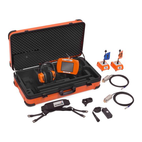
● F8 wireless headphones (optional) ● AC 200 SK 4 case The system can be transported and stored in the case. The L AC/DC adapter can be used to recharge the batteries of the C 200, RT 200 and F8 components simultaneously inside the case. - Page 15 NOTICE! Risk of damage The surface of the touch screen is sensitive. ● Do not use any hard or sharp objects to tap the screen. ● Protect the touch screen against aggressive substances (e.g. acidic or abrasive detergents). A list of symbols that might appear on the touch screen can be found in section 6.2 on page 71.
-
Page 16: Carrying The System
● Microphone socket For connecting a microphone, e.g. UM 200 universal micro- phone. ● USB port The USB port is only used by SEWERIN Service staff for main- tenance work. Connectors Carrying systems (Vario, triangle, lap belt, hand loop) can be at- tached to the connectors. -
Page 17: Switching The Receiver On And Off
2.2.2.3 Switching the receiver on and off Switching on ● Press the on/off key until the LED turns green. Switching off 1. Briefly press the on/off key. The Switch offdialog will appear. 2. Tap Switch off device. The receiver will switch off. 2.2.2.4 Automatic power off The power supply to the receiver is designed in such a way that a fully charged battery will allow one full day's work without in-... -
Page 18: Main View
2.2.2.5 Main view The touch screen of the receiver displays the main view when the system is ready for use. Fig. 7: Main view Fig. 8: Results display (detail of main view) The following is shown in the centre of the main view (fig. 8): ●... - Page 19 The main view also contains the following buttons: ● Measurement ● File ● Transmitter ● Pipe sections ● Filter ● Settings These buttons can be used to open submenus. Most of the but- tons also display information. The information displayed depends on the situation.
- Page 20 File The File menu is opened by pressing the Filebutton. The follow- ing actions can be performed in this menu: ● Save measurement ● Load saved measurement ● Delete saved measurement Fig. 10: File button For information about saving, loading and deleting measure- ments, please refer to section 3.4.3 on page 27.
- Page 21 For more detailed information about the Transmitter menu and listening to noises, please refer to section 3.7 on page 38. Pipe sections The Pipe sections button displays the following information: ● Total length of measuring section ● Number and length of pipe sections ●...
- Page 22 Filter The Filter button displays the following information: ● Correlation curve ● Marker Corresponds to the leak position. Fig. 13: Filter button The Filter menu is opened using the Filter button. This menu allows you to optimise the correlation result using filters. For more detailed information on filters, please refer to sec- tion 3.5 on page 31.
-
Page 23: How Interference Suppression Works
The Settings menu is opened using the Settings button. The following settings can be adjusted in this menu: ● Measurement ● Device For more detailed information on the Settings menu, please refer to section 4 on page 45. 2.2.2.6 How interference suppression works The interference suppression function allows you to exclude nois- es from the correlation that may have a negative effect on the result (e.g. -
Page 24: Rt 200 Transmitter
2.2.3 RT 200 transmitter The RT 200 transmitters send the measurement data from the microphones to the C 200 receiver. The transmitters are always used in pairs. The two transmitters are marked with a number and a colour to make them distinct. ●... - Page 25 This function can be used to adjust the noise transmission to the current situation. For example, when performing correlation on plastic pipes, the quality of the measurement can be improved if necessary using the low pass setting. The options are: ●...
-
Page 26: Switching The Transmitter On And Off
2.2.3.2 Switching the transmitter on and off Switching on The transmitter automatically switches on as soon as a micro- phone is connected. Switching off The transmitter automatically switches off as soon as the micro- phone is disconnected from the transmitter. For more detailed information about the plug connection between the microphone and the transmitter, please refer to section 2.4 on page 20. -
Page 27: Hy 200 Hydrophone
CAUTION! Danger when using the contact adapter The contact adapter contains a strong magnet. ● Keep the contact adapter away from magnetic storage media (e.g. hard drives, credit cards) and medical de- vices (e.g. pacemakers, insulin pumps). Note: The contact adapter comes with a protective screen, ●... -
Page 28: Filter Options (Overview)
Filter options (overview) Filters can be used both on the transmitter and the receiver. Fil- ters are used for different purposes. ● RT 200 transmitter − The bandpass can be adjusted using the filter key. This set- ting determines the extent to which incoming signals are sent to the receiver (section 2.2.3.1). -
Page 29: Power Supply To The Components
The battery compartments of the components contain parts that could get damaged when the batteries are being replaced. ● Only SEWERIN service personnel or other authorised special- ists may replace rechargeable lithium-ion batteries. WARNING! Risk of explosion due to short circuit Faulty lithium-ion batteries can explode due to an internal short circuit. -
Page 30: System In Use
System in use Preparing the system Two suitable measurement locations must be found depending on conditions on the ground. Suitable measurement locations include, for example, fittings or the pipe itself. 1. Attach a microphone to each of the measurement locations. −... -
Page 31: Setting The Number Of Pipe Sections
Note: The quality of the correlation result depends greatly on the con- figuration of the pipe sections. ● Make sure you configure the pipe sections completely and cor- rectly in accordance with the conditions on the ground. ● Adjust the settings before starting the measurement. Any changes made after the start of a measurement will mean that it will not be possible to continue the measurement after- wards. -
Page 32: Adding A Pipe Section
3.3.1.1 Adding a pipe section The first pipe section is set on transmitter 1. ● Up to four more pipe sections can be added between the first pipe section and transmitter 2. ● New pipe sections are added to the right of the selected pipe section. -
Page 33: Adjusting The Pipe Data
3.3.2 Adjusting the pipe data Pipe sections are characterised by the following features: ● Length of pipe ● Diameter of pipe ● Pipe material ● Sound velocity in the pipe section Adjoining pipe sections in a measuring section can have differ- ent pipe data. -
Page 34: Starting A Measurement
3.4.1 Starting a measurement Note: The quality of the correlation result also depends on the general noise level at the start of a measurement. ● Wherever possible, try to start a measurement when there is no loud sound interference in the background (e.g. no passing vehicles, extraction from house connections). -
Page 35: Repeating A Measurement
3.4.2 Stopping a measurement Ongoing measurements can be stopped at any time. In order to achieve a reliable result, SEWERIN recommends: Not stopping the measurement until the marker, leak position and quality of the peak stop changing. The main view is open. A measurement is ongoing. -
Page 36: Loading A Saved Measurement
The main view is open. The measurement was stopped 1. Tap the File button. The File menu appears. 2. Tap the Save button. The Comment menu appears. 3. Measurements can be saved with or without additional infor- mation. ● Tap Confirm to save the measurement without additional information. - Page 37 Fig. 18: Load menu Top left: Filter by date button Centre: List of saved measurements 3. Tap the relevant measurement in the list. The measurement will immediately appear in the main view. Searching for saved measurements Date filters can be set in the list of saved measurements to search for specific measurements.
-
Page 38: Deleting A Saved Measurement
The list will show all the measurements that match the search criteria. The date filter settings are displayed on the Filter by date button. Fig. 19: Filter by date button Left image: No date filter set Right image: Date filter set (year: 2015, month: 01 January) 3.4.3.2 Deleting a saved measurement Saved measurements can be deleted individually. -
Page 39: Optimising The Correlation Result Using Filters
● To do this, tap the Clear button again. Delete mode is disa- bled. The dot on the Clear button turns grey again. The measurements in the list appear in black. ● Tap Back. Optimising the correlation result using filters Note: The SeCorr system has filter options for various purposes. -
Page 40: Filter Menu (Overview)
3.5.1 Filter menu (overview) The Filter menu displays the frequencies, correlation curve and the result of the measurement as a graph. Fig. 20: Filter menu Top: Frequency graph Centre: Correlation curve Bottom: Result of measurement and quality of peak Right (top to bottom): Lower filter limit, upper filter limit, current filter buttons Available filters Various filters can be applied. -
Page 41: Frequency Graph
3.5.1.1 Frequency graph The receiver displays the spectra of the noises in the frequency graph. Fig. 21: Frequency graph 1 Lower stopband, 2 Lower filter limit, 3 Graph of functions, 4 Passband, 5 Upper filter limit, 6 Upper stopband, 7 Frequency axis In the settings you can specify whether to display one or two functions (Measurement menu >... -
Page 42: Correlation Curve
3.5.1.2 Correlation curve The run time difference between the signals of the two transmit- ters is displayed in the correlation curve. Fig. 22: Correlation curve with marker (red rectangle) The area around the highest peak of the curve is marked with a red rectangle. -
Page 43: Selecting And Adjusting Filters
3.5.2 Selecting and adjusting filters One filter is always set in the frequency graph when the Filter menu is opened. Whether an automatically calculated filter or a manually set filter is applied first depends on the starting point. Once the menu has been opened, you can switch between filters. Automatic filters are always recalculated when the Filter menu is opened. -
Page 44: Manually Adjusting Filters
3.5.2.2 Manually adjusting filters There are two ways of manually adjusting the filter limits: ● Quick adjustment ● Exact adjustment Performing a quick filter adjustment A quick adjustment involves resetting both filter limits. The Filter menu is open. 1. Tap the frequency graph (fig. 21) −... -
Page 45: Applying The Filters (Exiting The Filter Menu)
The Filter menu is open. 1. Tap either the Lower filter limit or the Upper filter limit but- ton. The Filter menu will change its appearance (fig. 25). The stopband of the filter limit that can be adjusted is shown in orange. -
Page 46: Plausibility Check (Moving The Marker)
Information about the radio connection during listening The C 200 receiver and F8 wireless headphones communicate by bidirectional SDR (SDR: Sewerin Digital Radio). SDR transmits uncompressed signals in real time. Radio inter- ference can, therefore, cause a short clicking noise in the head- phones. -
Page 47: Transmitter Menu (Overview)
● If you are carrying electronic devices that use WLAN and Blue- tooth directly on your body: Disable the WLAN and Bluetooth function if necessary. 3.7.2 Transmitter menu (overview) The Transmitter menu displays information about the transmit- ters connected by radio. The following noise settings can be adjusted: ●... -
Page 48: Adjusting The Volume
Information about the transmitters The following information appears as soon as an RT 200 trans- mitter is connected: ● Strength of radio signal at receiver ● Current noise level at transmitter ● Battery charge ● Bandpass setting Information about the GPS position of the transmitter is not cur- rently in use for technical reasons. -
Page 49: Selecting A Transmitter
The main view is open. 1. Tap the Transmitter button. The Transmitter menu will ap- pear. 2. Adjust the volume by tapping either: − the volume symbols − in the area between the two volume symbols Fig. 29: Adjusting the volume 3. -
Page 50: Microphone Function For Acoustic Leak Detection
The main view is open. 1. Tap the Transmitter button. The Transmitter menu will ap- pear. 2. Tap the relevant transmitter selection. The setting is applied immediately. The setting is stored until it is next adjusted. Microphone function for acoustic leak detection The microphone function is an extra function on the C 200 re- ceiver. - Page 51 Fig. 30: Microphone menu Fig. 31: Display of measurement values (detail of Microphone menu) 1 Current minimum noise level 2 Current noise level 3 Previous minimum noise level The following measurement values are displayed (fig. 31): ● Current noise level ●...
-
Page 52: Performing A Noise Measurement
menu). The volume must be set separately in the two menus. The setting procedure is identical. The Light button can be used to switch the microphone’s light source on and off. 3.8.2 Performing a noise measurement The current noise level is always displayed in the Microphone menu. -
Page 53: Settings
Settings Overview All settings are managed using the C 200 receiver. The settings can be changed at any time. The following menus are available: ● Measurement ● Device Setting options The settings in the Measurement and Device menus are imple- mented as follows: ●... -
Page 54: Selecting
4.2.1 Selecting Fig. 33: Selecting a setting (sample diagram) Top: Setting selected Bottom: Setting not selected Selected settings are indicated by the tick symbol. 1. In one of the menus, tap on the menu item for which you wish to change the setting. A sub-menu will appear. - Page 55 Picklist Fig. 35: Picklist Values are set using the arrow keys. 1. Tap on an arrow key. − The up key increases the value. − The down key decreases the value. 2. Apply the settings by pressing Confirm. The receiver goes back up a menu level. Numeric keypad Fig.
-
Page 56: Settings In The Measurement Menu
Settings in the Measurement menu The settings in the Measurement menu apply to the measure- ments. General > Metric Units Anglo-American Interference suppression > high Correlation curve > Positive Positive & negative Blocking filter > 60 Hz 50 Hz Filter basis >... -
Page 57: General
The main view is open. 1. Tap the Settings button. The Settings menu appears. 2. Tap the Measurement button. The Measurement menu ap- pears. 3. Adjust the settings as required. The Measurement menu is divided into three views General, Filter basis and Pipe data (Default). Switch between the views using the Scroll buttons. -
Page 58: Interference Suppression
Interference suppression is enabled. Only very loud noises are excluded from the correlation. ● Off Interference suppression is disabled. SEWERIN recommends: Use the low setting when enabling the interference suppression. 4.3.1.3 Correlation curve The correlation curve can be displayed in different ways. -
Page 59: Filter Basis
4.3.2 Filter basis The noises can be displayed as a graph based on different func- tions in the Filter menu. The options are: ● Coherence ● Cross spectrum ● Spectrum 1 ● Spectrum 2 Up to a maximum of two functions can be displayed at the same time. -
Page 60: Spectrum 1 Or Spectrum 2
The default values, which are automatically assigned to each new pipe section created, are set in the Pipe data (Default) view. SEWERIN recommends: When selecting default settings, choose typical values that commonly occur in your everyday work. For example, if you primarily work on cast iron pipes, set the mate- rial to cast iron. -
Page 61: Settings In The Device Menu
The calculated value can be changed. This change is saved tem- porarily. However, as soon as other settings are selected for the diameter or the material, the sound velocity is recalculated. ● Value range: 100 m/s – 2000 m/s ● Decimal places: None Settings in the Device menu The settings in the Device menu apply to the receiver. -
Page 62: General
The main view is open. 1. Tap the Settings button. The Settings menu appears. 2. Tap the Device button. The Device menu appears. 3. Adjust the settings as required. The Device menu is divided into the four views General, Time/Date, Region and Service. −... -
Page 63: Detect Position
Note: This function helps save energy. It means that the receiver can be used for longer without being recharged. The options are: ● 30 s | 1 min | 15 min | 30 min Duration that can be selected. ● Off The backlight does not switch itself off. -
Page 64: Time/Date
4.4.2 Time/Date 4.4.2.1 Time The receiver features an internal clock. The time is used to iden- tify the measurements. Note: The format of the time can be set under Time format in the menu. 4.4.2.2 Date The date is used to identify the measurements. Note: The format of the date can be set under Date format in the menu. -
Page 65: Time Format
4.4.3.2 Time format The time can be written in various ways. The options are: ● 12 h 12 hour clock ● 24 h 24 hour clock 4.4.3.3 Language The text on the user interface can be displayed in various lan- guages. -
Page 66: Servicing
Servicing Charging the batteries The batteries of the following components must be charged as required: ● C 200 receiver (lithium-ion rechargeable battery) ● RT 200 transmitter (lithium-ion rechargeable battery) ● F8 wireless headphones (NiMH rechargeable battery) The typical charging time is less than 7.5 hours. The batteries are protected against overcharging. -
Page 67: Charging Batteries Using The Ac/Dc Adapter Or Vehicle Cable
Fig. 39: AC 200 SK 4 case White circles: Connection cable Black arrow: Connection socket (outside) 1. Place the components in the dedicated spaces in the case. 2. Connect the components using the connection cables. 3. Connect the case to the power supply using AC/DC adapter L. Charging starts automatically. -
Page 68: Handling Faulty Lithium-Ion Rechargeable Batteries
● Lithium-ion batteries must only be removed if there is reason- able suspicion that they might be faulty. ● Only SEWERIN Service personnel or an authorised specialist may replace rechargeable batteries. 5.2.1... -
Page 69: Removing The Battery From The C 200 Receiver
5.2.2 Removing the battery from the C 200 receiver NOTICE! Risk of damage when removing lithium-ion batteries There are parts in the battery compartment of the receiver which can get damaged when removing the batteries. ● Always read section 5.2 and section 5.2.1 before removing the batteries. -
Page 70: Removing The Battery From The Rt 200 Transmitter
NOTICE! Risk of damage from electrostatic discharge There is an aerial in the battery compartment cover. That is why the battery compartment cover has an electrical connection (ca- ble) from the inside into the device interior. ● Ensure that the cable does not get severed. ●... -
Page 71: Calibrating The Touch Screen
4. The battery is fixed in place in the bottom section of the hous- ing by means of a retaining plate. Undo the three screws on the retaining plate. 5. Remove the battery. 6. Screw down the retaining plate again. 7. -
Page 72: Care
SEWERIN recommends: Always remove significant contamina- tion immediately. Maintenance SEWERIN recommends: Have the system serviced regularly by SEWERIN Service or an authorised professional. Only regular servicing can ensure that the system is always ready for use. 64 │ 5 Servicing... -
Page 73: Appendix
Appendix Technical data 6.1.1 C 200 receiver Device data Dimensions (W x D x H) 225 x 62 x 155 mm Weight 1.2 kg Material Polycarbonate (housing) Certificates Certificate FCC, CE, IC, MIC Marking Contains: FCC ID WSP-EZ1300102 IC 7994A-EZ1300102 Features Display 5.7”... - Page 74 AC/DC adapter L (charge in case) Data logging Filter automatic or manual Sampling rate 16 bit, 24 kHz Data transmission Near-field radio SDR (SEWERIN Digital Radio) Transmission frequency 433.9/434.4 MHz 2.408 – 2.476 444.5500/444.9875 MHz GHz, 38 channels 458.5125 /458.7875 MHz 468.5/469.6 MHz...
-
Page 75: Rt 200 Transmitter
6.1.2 RT 200 transmitter Device data Dimensions (W x D x H) 115 × 115 × 68 mm 115 × 115 × 244 mm with aerial Weight 430 g (with aerial) Material Polycarbonate (housing) Models country-specific Certificates Certificate FCC, CE, IC Marking –... - Page 76 Power supply Power supply lithium ion battery (rechargeable) [1357-0002], built-in Operating time, minimum > 8 h (23 °C) Battery power 24 Wh Charging time < 6 h Charging temperature 0 °C – +45 °C Charging voltage 12 V Charging current 1.2 A Charger AC/DC adapter L (charge in case)
-
Page 77: Um 200 Universal Microphone
6.1.3 UM 200 universal microphone Device data Dimensions (H × Ø) 123 x 45 mm (without cable) Weight 1055 g Material Stainless steel Models 3 cable lengths available Features Signal light 2 LEDs white (each 15 cd) Operating conditions Operating temperature -20 °C –... -
Page 78: Hy 200 Hydrophone
6.1.4 HY 200 hydrophone Device data Dimensions (W × H) 55 × 115 mm Weight 700 g (without cable) Material Stainless steel Operating conditions Operating temperature -20 ºC – +80 ºC Storage temperature -25 ºC – +80 ºC Atmospheric pressure water pressure up to 16 bar Protection rating IP68... -
Page 79: Symbols On The Touch Screen Of The C 200 Receiver
Symbols on the touch screen of the C 200 receiver The following tables provide an overview of what the main sym- bols represent. The symbols can also occur in combination dur- ing the program sequence. Many symbols on the touch screen can be displayed in different ways: ●... - Page 80 Symbol Significance Symbol Significance Volume Selected Volume low Next Volume high Move Brightness Noises from transmitter Brightness low Noises from transmitter 1 Brightness high Noises from transmitter 2 Light on No noises from microphone transmitter File Listen to microphone Charge Signal strength Filter by date GPS position...
-
Page 81: Significance Of Led Signals
Significance of LED signals 6.3.1 C 200 receiver The LED indicates the operating status. Colour Type of Activation Significance signal (repeat) Green Light ● C 200 switched on permanently Flashing 0.1 s on > 0.9 s ● Battery charging (ongoing) Double 0.1 s on >... -
Page 82: Rt 200 Transmitter
6.3.2 RT 200 transmitter The large LED between the two keys indicates operating statuses (see table below). The three small LEDs above the filter key indicate the bandpass setting. Colour Type of Activation Significance signal (repeat) Green Light ● RT 200 switched on permanently Flashing 0.1 s on >... -
Page 83: Troubleshooting
Position detection ● Change the position of enabled; receiver in use of the receiver incorrect position of ● If necessary disable position detection (set- ting: Detect position) Touch screen or re- ● Contact SEWERIN ceiver faulty Service 6 Appendix │ 75... -
Page 84: Accessories
Other accessories are available for the system. Please contact our SEWERIN sales department for further information. Declaration of conformity Hermann Sewerin GmbH hereby declares that the C 200 receiver and RT 200 transmitter fulfil the requirements of the following guideline: ●... -
Page 85: Licences In The Eea
Licences in the EEA The RT 200 transmitter may only be used in the following coun- tries of the European Economic Area (EEA) and only at the cor- responding frequencies. Note: Also refer to the advice regarding near-field radio in section 1.5. Austria 433.9000/434.4000 MHz Belgium... -
Page 86: Note About The Firmware (Open Source Software)
The firmware is based on open source software. The source code is provided in accordance with the licence terms for this open source software (GPL / LGPL). Hermann Sewerin GmbH stresses that it is not responsible for the source code and it does not form part of the services due. -
Page 87: Index
Index Overview 20 Selecting 35 Acoustic leak detection 42 Transmitter options 16 Aerial 17 Filter basis 51 Auto 1 or Auto 2 32 Frequency graph 33 automatic power off 9 High pass 17 Bandpass 16 Hydrophone 19 Blocking filter 50 Brightness 55 automatic 55 Information 57... - Page 88 Preparing 22 Repeating 27 SDR (Sewerin Digital Radio) 4 Saving 27 Select 46 Starting 26 Settings Steps (overview) 22 Button 14 Stopping 27 Device 53 Microphone Enable/disable 46 Connecting 20 Measurement 48 Microphone function 42 Options 45 Minimum noise level 43...
- Page 89 Hermann Sewerin GmbH Robert-Bosch-Straße 3 33334 Gütersloh, Germany Tel.: +49 5241 934-0 Fax: +49 5241 934-444 www.sewerin.com info@sewerin.com SEWERIN SARL Sewerin Ltd 17, rue Ampère – BP 211 Hertfordshire 67727 Hoerdt Cedex, France Tél. : +33 3 88 68 15 15...
Need help?
Do you have a question about the SeCorr C 200 and is the answer not in the manual?
Questions and answers