
Subscribe to Our Youtube Channel
Summary of Contents for FAFCO Sunsaver
- Page 1 ® ® SUNSAVER ® S o l a r P o o l H e a t i n g S y s t e m s I N S T A L L A T I O N M A N U A L...
-
Page 2: Table Of Contents
® ® Installation Manual Table of Contents System Overview Theory of Operation Specifications, Certifications & Listings Components & Parts List System Overview Safety & Disclaimer Quick Tips PHASE I — Site Preparations & Planning Collector Layout Spacing Collectors and Penetrations Plumbing Layout Supporting PVC Pipe Plumbing Materials... - Page 3 Various Plumbing Configurations and High Point Return Plumbing with Balancing Valves, No High Point Return Plumbing Movement Bank and Plumbing Movement Appendix D — Roof Mounting Details SunSaver Collectors on Composition Roofs ® SunSaver Collectors on Barrel Tile Roofs ®...
-
Page 4: System Overview
This manual pro- ® vides a step-by-step installation procedure for most applications. For those situations not covered in this manual, please contact your FAFCO representative. ® Please read this manual completely before starting the installation and take special care to comply with all local ordinances and building codes. -
Page 5: Specifications, Certifications & Listings
® System Overview Cont’d Specifications, Certifications & Listings ® SunSaver Collector Specifications Collector Area 48ft , 40ft , 32ft , 24ft , 20ft , 16ft Collector Dimensions (HxWxD) 4ft x (12ft, 10ft, 8ft), 2ft x (12ft, 10ft, 8ft) 22.0 (48ft ), 19.0 (40ft... -
Page 6: Components & Parts List
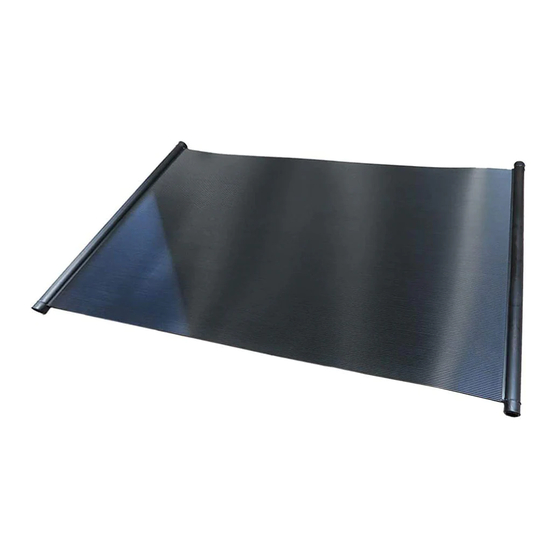
Image Name Description ® ® SunSaver 4ft SunSaver Collectors. These 4ft wide Collectors are available in three 822 (12ft) different lengths, 12ft (48 sq.ft.), 10ft (40 sq.ft.) and 8ft (32 sq.ft.) (4ft x 12 ft) 820 (10ft) (4ft x 10 ft) - Page 7 ® Components & Parts List Cont’d SunSaver Kits Available Item P/N Purpose/Use Contents Plumbs and mounts a Collector Pack collector. (One per Collector) Terminates plumbing (1) CPVC end cap, (1) vacuum relief valve, (2) and mounting a single CPVC female adapters, (7) tie-down caps, (7) tie- bank, adds a check down bases, (4) clamps, (2) 5˝...
- Page 8 ® Components & Parts List Cont’d Alternate Vendor Components Item Image Component Purpose/Use Suggested Vendors Isolation Valves Enables isolation of solar (use for (2-way pool, gate, or winterization or troubleshooting purposes) ball valves) Can enable manual draining of a system (use when a solar system is located below Manual Vertical pool level or to drain roof plumbing in...
-
Page 9: System Overview
FAFCO ® -sourced parts and standard equipment. The above figure and the component list below depicts standard equipment components and shows the proper placement of all components. All FAFCO ® SunSaver ®... - Page 10 Array Layout Components The typical SunSaver ® solar pool system consists of a combination of FAFCO ® -sourced parts and standard equipment. The above figure and the component list below depicts common Array Layout Components and shows the proper placement of all components.
-
Page 11: Safety & Disclaimer
• Mid-bank obstacles should maintain a clearance of 2” from collectors. See Appendix C for specific exceptions. • Plumbing Offsets may be used to allow for lateral movement between SunSaver banks and system plumbing as ® shown in Phase I—Site Preparations & Planning Figures 6 and 7 and in Figures 19 through 22 of Appendix C. -
Page 12: Phase I - Site Preparations & Planning
PHASE I — Site Preparations & Planning Planning a roof layout for necessary penetrations, mounting, and plumbing will make installation easier and pro- mote a cleaner looking system. While SunSaver systems install quickly, there are some special considerations to ®... -
Page 13: Plumbing Layout
Row-to-piping connections may only be installed in the End Supply/Return or Reverse/Return styles. To en- sure each collector receives adequate flow, install End Supply/Return rows with a maximum of 10 SunSaver ® ... - Page 14 ® PHASE I — Site Preparations & Planning Cont’d Figure 6 | Row Plumbing Movement A straight line of plumbing can move up 1” for a length of 25ft. Plumbing Expansion Joints are advised to accommodate this movement. An industry standard method, such as an offset should be used so that the line can move as needed.
-
Page 15: Supporting Pvc Pipe
ASTM D1785 or equivalent standard. tems, including FAFCO ’s CoolPV panels. ® ® PVC is generally an acceptable material for plumbing The best way to install a hybrid SunSaver /CoolPV ® ® FAFCO solar thermal systems. In most cases, an oper- ®... -
Page 16: Phase Ii - System Installation Detail
® PHASE II — System Installation Detail Mounting Collectors Note: It is crucial that the collector couplers and Be mindful when handling SunSaver collectors. hose clamps are installed properly. If improperly ® Rough handling can cause unnecessary body damage positioned, the hose clamps and couplers can... -
Page 17: Connect Supply & Return Lines
PHASE II — System Installation Detail Cont’d Connect Supply & Return Lines 5” EPDM hose couplers are used to make a semi flexi- ble connection from a SunSaver bank to Schedule 40, ® 2” PVC piping. Below is the best order to follow for con- necting the supply and return lines: 1. -
Page 18: Vrv & End Caps
To Pool side. (In some cases, plumbing the Diverter with a Neutral flow position (depicted) can allow partial flow to the solar and overheat the pool. on the highest bank. Note that it’s permissible to install Consult your local install department or FAFCO ® for further details.) -
Page 19: Pool Equipment Tie In
Thermal System Automation the pool equipment. Automating the solar pool heating system is not re- Pool Plumbing quired, though is highly recommended by FAFCO . Sys- ® The solar thermal system is installed after the pump tems that are automated will be able to run when ambi- and filter but before additional pool equipment. -
Page 20: Phase Iii - Commissioning
Appendix B. Pool Temperature Sensor A sensor is used to ensure that the controller is alerted Once the documents are complete, use FAFCO ’s ® when the pool temperature is too low. online portal to obtain a system warranty registration number. -
Page 21: Phase Iv - Routine Maintenance
® PHASE IV — Routine Maintenance Winterization Spring Startup Spring Startup for SunSaver solar collectors is essen- ® Note: Collectors are not warranted against freeze tially the opposite order of winterizing but also includes damage. checking for leaks and any damage which could have... - Page 22 ® PHASE IV: Routine Maintenance VRV: Winter: Removed Summer: Installed Body Straps End Caps: Drain Valves: Winter: “Open” Summer: “Closed” 2 Automation: Winter: “OFF” Summer: “ON” Isolation Valves: Winter: “OFF” Summer: “ON” Figure 13| Solar System Maintenance Figure 13 depicts the components to decommission, remove or reinstall during sys- tem Winterization, Summerization or when performing other routine maintenance.
-
Page 23: Pool Maintenance
Refer to the product warranty policy backwashing, or pool vacuuming (see Figure 13 for for information regarding other damages. component locations): In order to repair a tube leak, use only a FAFCO Col- ® 1. Turn the pump and solar system “OFF” (1 & 2) lector Repair Kit. -
Page 24: Closing Checklist
The centermost collector in a bank should be “Fix-Mounted” so that the rest of the bank moves about the centermost collector (Fix-Mounted Panel may be located elsewhere if governed by another factor) Each SunSaver Collector is mounted and spaced to allow for thermal expansion and contraction ®... -
Page 25: Appendix A - Commissioning & Warranty Registration
® APPENDIX A — Commissioning and Warranty Registration Commissioning and Warranty Registration This document is to be filled out by the lead solar installer during installation of your SunSaver System. Keep this form in ® a safe location and be sure to upload a copy during the online portal registration process. -
Page 26: Appendix B - Pump Sizing
(total pipe length used) Equivalent Sys Straight Pipe Length (ft) Box O (M+N) # Collectors on Roof/# Rows Average Bank Size Pressure Drop (ft) SunSaver Eq Head Box R Box P Box Q Loss (ft) (Box P result) (Box Q*5.1 ft ea. panel) -
Page 27: Example Pump Sizing Calculation
(total pipe length used) Equivalent Sys Straight Pipe Length (ft) Box O (M+N) # Collectors on Roof/# Rows Average Bank Size Pressure Drop (ft) SunSaver Eq Head Box R Box P Box Q Loss (ft) (Box P result) (Box Q*5.1 ft ea. panel) 20.4... -
Page 28: Example Manufacturer's Pump Curves
® APPENDIX B — Pump Sizing Example Manufacturer’s Pump Curves 85FT Recommended Pump Speed Curve 85 FT Recommended Setting... -
Page 29: Appendix C - Reference Tables & Figures
APPENDIX C — Reference Tables & Figures Bank Movement Clearances Table 3 | Obstacle Clearance ® Under normal movement of a SunSaver bank, each collector will have an Obstacle Clearances Needed incremental growth and contraction factor of 1/4” for each collector away... -
Page 30: Various Plumbing Configurations And High Point Return
I) STACKED REVERSE RETURN II) STACKED SAME END RETURN Figure 16 | High Point Return Line Multi-Bank SunSaver ® Pool Systems utilize a common high point return line enabling each bank to have proportional feed and return line backpressures which limits the water to favor the path of least resistance. Notice I) is an example of a stacked Reverse Return and II) is... -
Page 31: Plumbing With Balancing Valves, No High Point Return
Plumbing with Balancing Valves, No High Point Return Figure 17 | Balancing Valve Technique Multi-Bank SunSaver ® Pool Systems utilize balancing valves on the supply line enabling each bank to have proportional feed which limits the water to favor the path of least resistance. Notice A) is an example of a Reverse Return Multi-Bank system where the balancing valves are needed and B) is a Single Bank Reverse Return which doesn’t need balancing valves. -
Page 32: Plumbing Movement
® APPENDIX C — Reference Tables & Figures Plumbing Movement Direction of Guide Supports Plumbing Only Movement Figure 18 | PVC Plumbing Offset Right: A common industry standard for a plumbing offset (see Table 5 below for offset distance L). This offset can be oriented vertically (as shown) or hori- zontally to accommodate thermal movement in the direc- tion of the plumbing. -
Page 33: Bank And Plumbing Movement
® APPENDIX C — Reference Tables & Figures Plumbing Movement Figure 20 | Flexible PVC Offset Fixed *Flexible PVC Hose Support (~4ft) (2X) Straight Line Plumbing Guide Fixed Supports Support Length of Pipe Expansion Dimensions Chart Flexible PVC Line Offsets T=80°F Most Installations Most Installations, with Bank Movement Uncommon Installations... -
Page 34: Appendix D - Roof Mounting Details
® APPENDIX C — Reference Tables & Figures Bank and Plumbing Movement DIAGRAM LEGEND: Bank Moves up to 5X Plumbing Fix-Mounted Collector* Guide Fixed Points (±1/4”) = 2.5” Expansion Support Joint Plumbing Fixed Expansion Support Joint ~10ft L/4 = 7” min ~4ft Plumbing Bank Moves up to 5X... -
Page 35: Sunsaver ® Collectors On Composition Roofs
® APPENDIX D — Roof Mounting Details ® SunSaver Collectors on Composition Roofs NOTE: If local codes allow the bolt to be secured only into the sheathing, be sure not to overtighten bolts. Figure 23 | Composition Roof Mounting The figures depict an example of mounting on a composition shingle roof. Sub-... -
Page 36: Sunsaver ® Collectors On Barrel Tile Roofs
® APPENDIX D — Roof Mounting Details ® SunSaver Collectors on Barrel Tile Roofs Figure 24 | Tile Roof Mounting The figure depicts an example of mounting on a Barrel Tile Roof. Substrate is required to support and protect the collectors from abrasion and uneven contours but may be substituted by a roof rack with support from runners not exceeding 16”... -
Page 37: Sunsaver ® Collectors Wood Rack Mounted
® APPENDIX D — Roof Mounting Details ® SunSaver Collectors on Flat Tile Roofs Figure 25A | Tile Stand Off Method Figure 25B | Tile Clip Method The figures depict examples of mounting on Flat Tile roofs. Substrate is required to support and protect the collec- tors from abrasion but may be substituted by a roof rack with support from runners not exceeding 16”... -
Page 38: Sunsaver ® Collectors Metal Rack Mounted
® APPENDIX D — Roof Mounting Details ® SunSaver Collectors Wood Rack Mounted Figure 26 | Wood Ground Rack Mounting The figures depict examples of a wood ground rack. Substrate is not required if the rack has runners at a minimum spacing of 16”. If the rack has spacing greater than 16”, a substrate must be used to support the collector from excessive sagging. - Page 39 ® APPENDIX D — Roof Mounting Details ® SunSaver Collectors Metal Rack Mounted Figure 27 | Metal Ground Rack Mounting The figures depict examples of a metal ground rack. Substrate is not required if the rack has runners at a minimum spacing of 16”. If the rack has spacing greater than 16”, a substrate must be used to support the collector from excessive sagging.
-
Page 40: Appendix E - Alternate Methods Of Compliance
® APPENDIX E — Alternate Methods of Compliance Acceptable Installation of Valves Figure 28| Diverter Valve on Supply, Isolation on Return The below figures depict alternate types and locations of the diverter valve and check/isolation valve. Non-draining configurations should be manually drained for winter, self-draining systems do not require draining for winterization. - Page 41 ® APPENDIX E — Alternate Methods of Compliance Acceptable Installation of Valves Figure 29| Diverter Valve on Supply, Check Valve on Return The below figures depict alternate types and locations of the diverter valve and check/isolation valve. Non-draining configurations should be manually drained for winter, self-draining systems do not require draining for winterization.
- Page 42 ® APPENDIX E — Alternate Methods of Compliance Acceptable Installation of Valves Figure 30| Diverter Valve on Return, Isolation on Return The below figures depict alternate types and locations of the diverter valve and check/isolation valve. Non-draining configurations should be manually drained for winter, self-draining systems do not require draining for winterization.
- Page 43 ® APPENDIX E — Alternate Methods of Compliance Acceptable Installation of Valves Figure 31| Diverter Valve on Return, Check Valve on Return The below figures depict alternate types and locations of the diverter valve and check/isolation valve. Non-draining configurations should be manually drained for winter, self-draining systems do not require draining for winterization.
Need help?
Do you have a question about the Sunsaver and is the answer not in the manual?
Questions and answers