Table of Contents
Advertisement
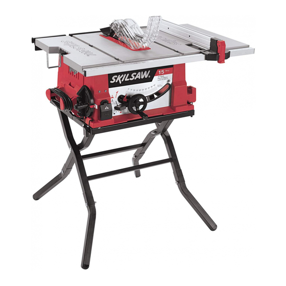
3410 2610013681 ENG:2610008499 7/20/10 2:14 PM Page 1
IMPORTANT:
Read Before Using
3410
Call Toll Free for
Consumer Information
& Service Locations
For English Version
See page 2
Lire avant usage
Operating/Safety Instructions
Consignes de fonctionnement/sécurité
Instrucciones de funcionamiento y seguridad
Pour obtenir des informations et
les adresses de nos centres de
service après-vente,
appelez ce numéro gratuit
1-877-SKIL999 (1-877-754-5999) www.skil.com
Version française
IMPORTANT :
Voir page 36
IMPORTANTE:
Leer antes de usar
Llame gratis para
obtener información
para el consumidor y
ubicaciones de servicio
Versión en español
Ver la página 70
Advertisement
Table of Contents

Related Manuals for Skil 3410


Summary of Contents for Skil 3410
- Page 1 3410 2610013681 ENG:2610008499 7/20/10 2:14 PM Page 1 IMPORTANT: IMPORTANT : IMPORTANTE: Read Before Using Lire avant usage Leer antes de usar Operating/Safety Instructions Consignes de fonctionnement/sécurité Instrucciones de funcionamiento y seguridad 3410 Call Toll Free for Pour obtenir des informations et...
-
Page 2: General Safety Rules
3410 2610013681 ENG:2610008499 7/20/10 2:14 PM Page 2 General Safety Rules “READ ALL INSTRUCTIONS” Failure to follow the safety rules listed below and other basic safety precautions WARNING may result in serious personal injury. Work Area DRESS PROPERLY Do not wear loose clothing or jewelry. They can be caught in moving parts. -
Page 3: Additional Safety Rules
3410 2610013681 ENG:2610008499 7/20/10 2:14 PM Page 3 General Safety Rules Tool Use DIRECTION OF FEED Feed work into a blade or cutter against the direction of rotation of the blade or cutter only. DON T FORCE TOOL It will do the job better and safer at the rate for which it was NEVER LEAVE TOOL RUNNING UNATTENDED designed. - Page 4 3410 2610013681 ENG:2610008499 7/20/10 2:14 PM Page 4 Additional Safety Rules KICKBACKS AND POSSIBLE INJURY e. NEVER place your face or body in line with the cutting CAN USUALLY BE AVOIDED BY: tool. a. Maintaining the rip fence parallel to the sawblade.
- Page 5 3410 2610013681 ENG:2610008499 7/20/10 2:14 PM Page 5 Additional Safety Rules 11. KNOW YOUR CUTTING TOOLS d. Make sure the top of the cutting tool rotates toward you Dull, gummy or improperly sharpened or set cutting tools can when standing in normal operating position. Also make sure...
-
Page 6: Connection To A Power Source & Extension Cords
3410 2610013681 ENG:2610008499 7/20/10 2:14 PM Page 6 Connection to a Power Source This machine must be grounded while in use to protect the This power tool is equipped operator from electric shock. with a 3-conductor cord and grounding type plug, approved... -
Page 7: Table Of Contents
3410 2610013681 ENG:2610008499 7/20/10 2:14 PM Page 7 Table of Contents Page Page General Safety Rules .............2–3 Mounting the Table Saw ..........16 Additional Safety Rules ..........3–5 Adjustments ...............17–20 Connection to a Power Source & Extension Cords ...6 Adjusting 0° and 45° Positive Stops......17 Table of Contents...............7... -
Page 8: Glossary Of Terms
3410 2610013681 ENG:2610008499 7/20/10 2:14 PM Page 8 Glossary of Terms WORKPIECE burning of the workpiece or splintering. In general, heel cre - The item on which the cutting operation is being performed. ates a poor quality cut and can be a safety hazard. -
Page 9: Getting To Know Your Table Saw
3410 2610013681 ENG:2610008499 7/20/10 2:14 PM Page 9 Getting To Know Your Table Saw 1. POWER SWITCH FIG. 1 Switch incorporates hole for use with padlock to prevent accidental starting. 2. TABLE Provides large working surface to support workpiece. 3. BASE Supports table saw. -
Page 10: Smart Guard System
3410 2610013681 ENG:2610008499 7/20/10 2:14 PM Page 10 Getting To Know Your Table Saw 16. SMART GUARD SYSTEM FIG. 1 Consists of three key elements: Adjustable (3 position) Riving Knife, Anti-Kickback Device and Barrier Guard Device. All of these are part of a modular system that requires no tools to assemble or unassemble. -
Page 11: Unpacking And Checking Contents
This cord must remain unplugged whenever you are working on the table saw. Model 3410 Table Saw is shipped complete in one carton. Separate all parts from packing materials and check each one with the illus tration and the list of Loose Parts to make certain all items are accounted for before discarding any packing material (Fig. -
Page 12: Assembly
3410 2610013681 ENG:2610008499 7/20/10 2:14 PM Page 12 Assembly FIG. 5 Assembling the Leg Stand After completing adjustments, securely tighten WARNING all fasteners. An unstable stand may shift in use and cause serious personal injury. The stamped rails may have sharp edges. Be WARNING careful in handling the rails to prevent being cut. -
Page 13: Attaching The Smart Guard System
3410 2610013681 ENG:2610008499 7/20/10 2:14 PM Page 13 Attaching the Smart Guard System FIG. 8 To prevent personal injury, always dis con nect WARNING plug from power source before attaching or removing the Smart Guard System. POSITIONING THE RIVING KNIFE Remove table insert using finger hole. - Page 14 3410 2610013681 ENG:2610008499 7/20/10 2:14 PM Page 14 ATTACHING THE GUARD ASSEMBLY With one hand, hold the front of the barrier guard assembly 4 by the metal “fork.” With the other hand, hold the guard release lever 5 up (Fig. 10).
-
Page 15: Changing The Blade
This information DIENTES DE LA HOJA may not be printed on the blade s packaging. If not, check the manufacturer s catalog or website. Skil offers an extensive line of BLADE BODY PLATE MUST BE LESS THAN .088"... -
Page 16: Attaching Rip Fence
3410 2610013681 ENG:2610008499 7/20/10 2:14 PM Page 16 Assembly FIG. 18 Attaching Rip Fence Raise rip fence handle 1, so holding clamp 2 is out far enough to fit on the table 3 (Fig. 18). Position the rip fence 4 over table 3 holding up the front end, first engage holding clamp 2 with rear rail. -
Page 17: Adjustments
3410 2610013681 ENG:2610008499 7/20/10 2:14 PM Page 17 Adjustments FIG. 20 Adjusting 0° and 45° Positive Stops Your saw is equipped with positive stops for fast and ac curate positioning of the saw blade at 90° and 45° to the table. -
Page 18: Adjusting Blade Parallel To The Miter Gauge Slots
3410 2610013681 ENG:2610008499 7/20/10 2:14 PM Page 18 Adjusting Blade Parallel to FIG. 23 the Miter Gauge Slots The blade was adjusted parallel to the miter gauge slots at the factory. In order to ensure accurate cuts and help prevent kickback, this adjustment should be rechecked. -
Page 19: Aligning Rip Fence
3410 2610013681 ENG:2610008499 7/20/10 2:14 PM Page 19 Aligning Rip Fence FIG. 26 To prevent personal injury, always dis con nect WARNING plug from power source before making any adjustments. The rip fence must be parallel with the SAWBLADE in order to prevent KICKBACK when ripping. -
Page 20: Riving Knife Alignment
(Fig. 28). Paper 5 is used as a “Spacing Gauge.” NOTE: The spacing instructions above are based on using a standard kerf blade (.128" kerf on the Skil blade included). If a smaller kerf blade is used, adjust the paper spacer. For instance, if the kerf of the replacement blade is near .100", use 1 thickness... -
Page 21: Basic Table Saw Operation
Component Parts (figure 33): ‚ Riving Knife The Riving Knife is the central element of the Skil Smart Guard blade guarding system, serving as the attachment point for both the Main Barrier Guard and the Anti-Kickback Device. In the event that the Main Barrier Guard and Anti-... -
Page 22: Blade Bevel Control
3410 2610013681 ENG:2610008499 7/20/10 2:14 PM Page 22 Attachment/Removal (see pages 13–14 for detailed instructions) The three primary components of the Smart Guard blade guarding system are designed for rapid attachment, adjustment and/or removal without the need for additional tools. -
Page 23: Work Helpers
3410 2610013681 ENG:2610008499 7/20/10 2:14 PM Page 23 FIG. 38 Work Helpers Before cutting any wood on your saw, study all of the “Basic Saw Operations.” 1-1/2 Notice that in order to make some of the cuts, it is necessary to use WORKPIECE 45°... -
Page 24: Using The Miter Gauge
3410 2610013681 ENG:2610008499 7/20/10 2:14 PM Page 24 Using the Miter Gauge FIG. 42 CROSSCUTTING, MITER CUTTING, BEVEL CUTTING, COM POUND MITER CUTTING and when RABBETING across the end of a narrow workpiece, the MITER GAUGE is used. For your own safety, always observe the following... -
Page 25: Crosscutting
3410 2610013681 ENG:2610008499 7/20/10 2:14 PM Page 25 Crosscutting CROSSCUTTING is known as cutting wood across the grain, at 90°, or square with both the edge and the flat side of the wood. This is done with the miter gauge set at 90° (Fig. 43). -
Page 26: Repetitive Cutting
3410 2610013681 ENG:2610008499 7/20/10 2:14 PM Page 26 Repetitive Cutting FIG. 44 REPETITIVE CUTTING is known as cutting a quantity of pieces the same length without having to mark each piece (Fig. 44). When making repetitive cuts from a long workpiece, make sure it is supported. -
Page 27: Bevel Crosscutting
3410 2610013681 ENG:2610008499 7/20/10 2:14 PM Page 27 FIG. 46 Bevel Crosscutting BEVEL CROSSCUTTING is the same as crosscutting ex cept that the wood is also cut at a bevel angle (Fig. 46) … other than 90° with the flat side of the wood. - Page 28 3410 2610013681 ENG:2610008499 7/20/10 2:14 PM Page 28 FIG. 47 10. Do not pick up small pieces of cut-off material from the table. REMOVE them by pushing them OFF the table with a long stick. Otherwise they could be thrown back at you by the rear of the blade.
-
Page 29: Ripping
3410 2610013681 ENG:2610008499 7/20/10 2:14 PM Page 29 Ripping RIPPING is known as cutting a piece of wood with the grain, or lengthwise. This is done using the rip fence. Position the fence to the desired WIDTH OF RIP and lock in place. Before starting to rip, be sure: A. -
Page 30: Non Thru-Sawing
3410 2610013681 ENG:2610008499 7/20/10 2:14 PM Page 30 Non Thru-Sawing Add 8" high flat facing board to the fence, the full length of the fence (Fig. 52). Use featherboards for all “Non Thru-Sawing” operations (when FIG. 52 sawblade guard must be removed). Featherboards 1 are used to keep the work in contact with the fence and table as shown, and to stop kickbacks. -
Page 31: Dado Cutting
After work pieces have been properly dado cut, they can be tightly joined together. The 3410 B) Place the outer washer onto the outside of the dado table saw can accommodate dado cutting up to 13/16" wide in a stack. -
Page 32: Fig. 55
2610011337. Never mount a dado stack that is wider than 13/16". Lower the blades below the table top and insert the Skil Dado Table Insert (2610011337) 5 (Fig. 56). Raise the cutters to the desired depth of cut (above the insert). Check that the tool is not plugged into a power source;... -
Page 33: Special Cutting Techniques
3410 2610013681 ENG:2610008499 7/20/10 2:14 PM Page 33 Special Cutting Techniques This table saw is a highly versatile tool, ca pa ble of WARNING performing a wide range of highly specialized cuts that cannot be covered in this manual. Do not attempt to perform cuts not covered in this manual un less you are thoroughly familiar with procedures and fixtur ing. -
Page 34: Lubrication
3410 2610013681 ENG:2610008499 7/20/10 2:14 PM Page 34 Make sure the teeth of the ANTIKICKBACK pawls are al ways sharp. To sharpen: FIG. 57 Remove blade guard. Rotate pawl toward rear of spreader so that teeth are above top of spreader. -
Page 35: Troubleshooting
4. Burned out switch. REMEDY 1. Plug saw in. 2. Replace fuse or reset tripped circuit breaker. 3. Have cord replaced by an Authorized Skil Service Center or Service Station. 4. Have switch replaced by an Authorized Skil Service Center or Service Station.
Need help?
Do you have a question about the 3410 and is the answer not in the manual?
Questions and answers