
Related Manuals for Cascade CDO-28

Summary of Contents for Cascade CDO-28
- Page 1 Drying - Decarboxylation Oven 220 – 240 Voltage CDO-28 Installation - Operation Manual...
- Page 2 This oven requires permanent connect wiring to a power source (also known as a hardwiring). It does not connect with a power cord. P a g e cascadesciences.com Tel. 503 847-9047...
- Page 3 CDO Drying and Decarboxylation Oven 220 – 240 Voltage Part Number (Manual): 4861778 Revision: April 11, 2019 P a g e cascadesciences.com Tel. 503 847-9047...
-
Page 4: Table Of Contents
TABLE OF CONTENTS CERTIFICATIONS ..............................5 UNIT SPECIFICATIONS ............................. 7 Temperature Performance ..............................7 Power ......................................7 Airflow Performance ................................7 Weight ......................................8 Dimensions ....................................8 Capacity ....................................8 INTRODUCTION ................................ 9 Read this Manual ..................................9 Contacting Assistance ................................9 Engineering Improvements.............................. -
Page 5: Certifications
CERTIFICATIONS This certificate satisfies NRTL safety requirements TÜV SÜD CUE Certificate Number: U8 17 03 64872 070 These units are CUE listed by TÜV SÜD as forced air ovens for appropriate professional, industrial, or educational use. TÜV SÜD America Inc. is an OSHA recognized NRTL and a Standards Council of Canada accredited certification body. - Page 6 CERTIFICATIONS P a g e cascadesciences.com Tel. 503 847-9047...
-
Page 7: Unit Specifications
UNIT SPECIFICATIONS These ovens are 220 – 240 voltage single phase units. Please refer to the oven data plate for individual electrical specifications. Technical data specified applies to units with standard equipment at an ambient temperature of 25°C and at nominal voltage. The temperatures specified are determined in accordance to factory standards respecting the recommended wall clearances of 10% of the height, width, and depth of the inner chamber. -
Page 8: Weight
UNIT SPECIFICATIONS EIGHT Shipping Unit Weight 694 lb / 315 kg 255.4 lb / 115.8 kg IMENSIONS By Inches Exterior W × D × H Interior W × D × H 42.5 x 34.1 x 85.9 31.7 x 26.0 x 60.9 By Millimeters Exterior W ×... -
Page 9: Introduction
NGINEERING MPROVEMENTS Cascade Sciences continually improves all of its products. As a result, engineering changes and improvements are made from time to time. Therefore, some changes, modifications, and improvements may not be covered in this manual. If your unit’s operating characteristics or appearance differs from those described in this manual, please contact your oven dealer or customer service representative for assistance. - Page 10 INTRODUCTION 10 | P a g e cascadesciences.com Tel. 503 847-9047...
-
Page 11: Receiving Your Unit
RECEIVING YOUR UNIT NSPECT THE HIPMENT When a unit leaves the factory, safe delivery becomes the responsibility of the carrier. • Damage sustained during transit is not covered by the manufacturing defect warranty. • Save the shipping carton until you are certain that the unit and its accessories function •... -
Page 12: Orientation
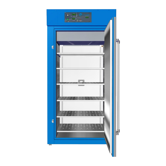
Intake Vent Control Panel Exhaust Vent Temperature Sensor Permanent Connect Wire Braid Probes 10-gauge, 6 inches (150 mm) Figure 1: CDO-28 Door Gasket Access Port (Back of Oven) Chamber Ceiling Liner Shelf Standard Mounting Rail 12 | P a g e cascadesciences.com... -
Page 13: Recording Data Plate Information
RECEIVING YOUR UNIT ECORDING LATE NFORMATION Record the oven serial number and model number below for future reference. Your distributor or Tech Support needs this information to provide accurate help during support calls and emails. The data plate is located on the back of the oven, below the power braid inlet. •... - Page 14 RECEIVING YOUR UNIT 14 | P a g e cascadesciences.com Tel. 503 847-9047...
-
Page 15: Installation
INSTALLATION ARDWIRE EQUIREMENT The oven requires permanent connect wiring (commonly known as hardwiring). Wiring to the power source must be performed by a qualified electrical technician. All other Installation steps may be performed by the operator. NSTALLATION ROCEDURE HECKLIST Carry out the procedures and steps listed below to install the oven in a new workspace location and prepare it for use. -
Page 16: Required Ambient Conditions
INSTALLATION EQUIRED MBIENT ONDITIONS This oven is intended for use indoors, at room temperatures between 59°F and 104°F (15°C and 40°C), at no greater than 80% Relative Humidity (at 77°F / 25°C). Operating the unit outside of these conditions may adversely affect its temperature range and stability. -
Page 17: Environmental Disruption Sources
INSTALLATION NVIRONMENTAL ISRUPTION OURCES When selecting a location to install the unit, consider all environmental conditions that can affect its temperature performance. For example: Proximity to other ovens, autoclaves, and any device that produces significant radiant heat • Heating and cooling ducts, or other sources of fast-moving air currents •... -
Page 18: Power Feed Wiring
INSTALLATION OWER IRING The oven comes provided with an integral 6-inch (150 mm) wire braid consisting of two 10-gauge hot wires and a 10-gauge earth ground. The wires for power source connection should be Green/Yellow – Earth; Black – Hot; Black – Hot. The oven must be earth grounded using the protective conductor terminal (green with yellow stripe wire). -
Page 19: Leveling
INSTALLATION EVELING Install the 4 leveling feet with the 4 corner holes on the bottom of the oven. The oven must be level and stable for safe operation. Note: To prevent damage when moving the unit, turn all 4 leveling feet so that the leg of each foot sits inside the unit. -
Page 20: Install The Shelving
INSTALLATION NSTALL THE HELVING The horizontal airflow within the chamber moves from the small duct holes on the right-hand side of the chamber to the large holes on the left side. Place the shelves as not to obstruct the duct holes on either side. -
Page 21: Graphic Symbols
GRAPHIC SYMBOLS The oven is provided with multiple graphic symbols on its exterior. The symbols identify hazards and the functions of the adjustable components, as well as important notes in the user manual. Symbol Definition Consult the user manual. Consulter le manuel d'utilisation Indicates adjustable temperature Indique température réglable AC Power... - Page 22 GRAPHIC SYMBOLS Symbol Definition Indicates the timer Indique le minuterie Start or Stop the Timer Lancer ou arrêter le minuteur Reset the Timer Réinitialiser la minuterie Caution hot surface Attention surface chaude 22 | P a g e cascadesciences.com Tel. 503 847-9047...
-
Page 23: Control Panel Overview
CONTROL PANEL OVERVIEW Figure 2: Control Panel Timer Switch The black Timer Switch controls power to the timer system. When this switch is in the ON position, the SET TIMER display illuminates, and the oven can run a timed steady-state heating profile at the current temperature set point. - Page 24 CONTROL PANEL OVERVIEW Heating Activated Light The green pilot light located beneath the label HEATING ACTIVATED illuminates whenever the workspace oven heating elements are powered and warming the oven. The oven uses measured pulses to achieve and maintain the temperature set point. OTL Light Marked OVER TEMPERATURE ACTIVATED, this light illuminates whenever the Over Temperature Limit heating cutoff system is routing power away from the heating elements.
-
Page 25: Operation
OPERATION Safe operation of the oven is dependent on the actions and behavior of the oven operators. Operating personnel must read and understand the Safety Guidelines and Operating Precautions in this section prior to operating the oven. The operators must follow these instructions to prevent injuries and to safeguard their health, environment, and the materials being treated in the oven, as well as to prevent damage to the oven. -
Page 26: Operating Precautions
OPERATION Warning Hot Surfaces: These areas are marked with Hot Surface labels. Proper protective equipment should be employed to minimize the risk of burns. Avertissement Surface Chaude: Ces zones sont marquées avec des étiquettes de surface chaude. Un équipement de protection approprié devrait être utilisé pour minimiser le risque de brûlures. PERATING RECAUTIONS Do not use this oven in unsafe improper applications that produce flammable or combustible... -
Page 27: Theory Of Operation
OPERATION HEORY OF PERATION Heating When powered, the oven chamber heats to and then maintains the currently programmed temperature set point. The set point may be adjusted by the operator using the Set Temperature controls. Heating is controlled by a microprocessor controller board that stores the temperature set point. The microprocessor senses the chamber air temperature via a solid-state probe located in the airstream on the back wall of the chamber. - Page 28 OPERATION Timed Heating Profile The oven is provided with a timer system that can run the oven in a steady-state heating profile at the current temperature set point from 1 minute up to 99 hours, 59 minutes. Allow the oven to heat to temperature prior to launching the profile.
-
Page 29: Put The Oven Into Operation
OPERATION UT THE VEN INTO PERATION Carry out the following steps and procedures to put the oven into operation after installing it in a new workspace environment. Place the oven Power Switch in the ON ( I ) position. The switch will illuminate. •... -
Page 30: Set The Temperature Set Point
OPERATION ET THE EMPERATURE OINT Adjust the oven temperature set point to that of your application. Navigate to the Temperature Set Point Adjustment mode Set Temperature Set Point Adjustment Mode Press and hold either Current Set Point The display will briefly flash the letters “SP”, then show the flashing, •... -
Page 31: Setting The Timer
OPERATION ETTING THE IMER This procedure enters a heating profile duration in the Timer system. When launched, the profile runs the oven for the duration at the present temperature set point. Turn on the Timer System Set Timer 1 Minute Profile Push to ON ( I ) The Timer Display will illuminate, showing the previously programmed... - Page 32 OPERATION Setting the Timer Continued Set the Tens-of-Minute parameter Set Timer 1 Hour, 51 Minutes Adjust Advance to the Minutes parameter Set Timer Press Minutes Selected The flashing decimal point will advance to between the third and fourth • numbers, saving the new Tens-of-Minutes parameter setting Set the Minutes parameter Set Timer 1 Hour, 55 Minutes...
-
Page 33: Launch A Heating Profile
OPERATION AUNCH A EATING ROFILE The oven can be run in a timed steady-state heating profile at the current temperature set point. Allow the oven to come up to temperature prior to launching a profile. See the Setting the Timer procedure on page 31 for how to set the length of the profile. -
Page 34: Venting The Exhaust Port
OPERATION ENTING THE XHAUST Optional: The oven does not require venting to operate. However, venting oven exhaust out of the workspace can help prevent elevated temperatures and the buildup of unpleasant odors. Obtain flexible, non-insulated ducting. • Attach the ducting to the lip of the exhaust port on the top, right side of the oven. See the •... -
Page 35: User Maintenance
USER MAINTENANCE Warning: Prior to maintenance or service on this unit, disconnect the power feed from the power supply. Avertissement: Avant d'effectuer toute maintenance ou entretien de cet appareil, débrancher le cordon secteur de la source d'alimentation. LEANING AND ISINFECTING If a hazardous material or substance has spilled in the oven, immediately initiate your site Hazardous Material Spill Containment protocol. -
Page 36: Door Components
USER MAINTENANCE Disinfecting Disinfect the oven if algae, mold, bacteria, or other biological contaminants are an issue. For maximum effectiveness, disinfection procedures are typically performed after cleaning. Keep the following points in mind when disinfecting the oven: Turn off and disconnect the unit to safeguard against electrical hazards. •... -
Page 37: Calibrating The Temperature Display
The device must be accurate to at least 1°F and should be regularly calibrated by a third party. Never use alcohol or mercury based thermometers. Cascade Sciences CDO ovens do not normally require calibration. Should your SOP or Quality program require calibrations, follow this guideline. - Page 38 USER MAINTENANCE 6 ) Heat up and stabilization period. The oven chamber must be stable at temperature in order to perform an accurate • calibration. The temperature is considered stabilized when the oven chamber has operated at your • calibration temperature for at least 30 minutes with no fluctuations of ±1°F or greater. 30 Minute Minimum Stability Period 240°F...
- Page 39 USER MAINTENANCE Calibration continued Place the oven in temperature calibration mode. Set Temperature a. Press and hold both the UP and DOWN arrow buttons simultaneously. Set Temperature The Temperature Display will show the letters “C O”, • then begin flashing the current temperature value. Note: If an arrow key is not pressed for five seconds, the Current Temp.
- Page 40 USER MAINTENANCE Calibration continued After the oven has achieved the set point, Reference Device wait for the oven chamber temperature to stabilize. The chamber temperature is stabilized • when no fluctuations of ±1°F or greater have been detected with the reference device for a minimum of 30 minutes.
-
Page 41: Parts List
PARTS LIST Description Parts Number Description Parts Number Adjustable Leveling Feet Shelf Slider Right 2700506 5121845 Door Gasket Fiberglass with Shelf Slider Left clips, 1 ft section Requires 17 feet for a complete replacement. 3450642 5121844 Shelf Assembly, 23” x 31” 995-00005 41 | P a g e...
Need help?
Do you have a question about the CDO-28 and is the answer not in the manual?
Questions and answers
We have a Cascade Sciences Decarb Over. The handle of the door needs replacing and I can not find any spare parts.
The context does not provide specific information on where to find spare parts for the Cascade Sciences Decarb Oven model CDO-28, including the door handle. However, it suggests contacting your distributor or Technical Support for assistance with electrical systems, which may also apply to other components like the door handle.
This answer is automatically generated