Table of Contents
Advertisement
Owner's Manual & Safety Instructions
Save This Manual
operating, inspection, maintenance and cleaning procedures. Write the product's serial number in the
back of the manual near the assembly diagram (or month and year of purchase if product has no number).
Keep this manual and the receipt in a safe and dry place for future reference.
Email our technical support at: productsupport@harborfreight.com
When unpacking, make sure that the product is intact
and undamaged. If any parts are missing or broken,
please call 1-888-866-5797 as soon as possible.
Copyright
©
2000 by Harbor Freight Tools
No portion of this manual or any artwork contained herein may be reproduced in
any shape or form without the express written consent of Harbor Freight Tools.
Diagrams within this manual may not be drawn proportionally. Due to continuing
improvements, actual product may differ slightly from the product described herein.
Tools required for assembly and service may not be included.
Keep this manual for the safety warnings and precautions, assembly,
Visit our website at: http://www.harborfreight.com
Email our technical support at: productsupport@harborfreight.com
Visit our website at: http://www.harborfreight.com
®
. All rights reserved.
Read this material before using this product.
Failure to do so can result in serious injury.
SAVE THIS MANUAL.
19c
Advertisement
Table of Contents

Subscribe to Our Youtube Channel
Related Manuals for Central Machinery 38470


Summary of Contents for Central Machinery 38470
- Page 1 Owner’s Manual & Safety Instructions Save This Manual Keep this manual for the safety warnings and precautions, assembly, operating, inspection, maintenance and cleaning procedures. Write the product’s serial number in the back of the manual near the assembly diagram (or month and year of purchase if product has no number). Keep this manual and the receipt in a safe and dry place for future reference.
-
Page 2: Technical Specifications
If there is any doubt, do not operate the tool. 14. Maintenance. For your safety, maintenance should be performed regularly by a qualified technician. Page 2 For technical questions, please call 1-888-866-5797. Item 38470... -
Page 3: Welding Precautions
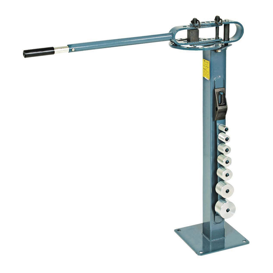
Exercise extreme caution to prevent burns to yourself or others. 16. Read and adhere to all warnings and instructions in the instruction manual provided by the manufacturer of the welder being used. Item 38470 For technical questions, please call 1-888-866-5797. Page 3... - Page 4 Figure B: Assemble Handle 6. Place the Outer Handle Die Receiver (9) between the Die Receiver (10) and secure it in place using one of the Long Hitch Pins (1). Page 4 For technical questions, please call 1-888-866-5797. Item 38470...
-
Page 5: Basic Operation
1. Place the Support Pin (5) into the hole under the Square Stop Block (3) so that the Square Stop Block (3) will sit correctly in relation to the Ring Assembly/ Die Receiver. Item 38470 For technical questions, please call 1-888-866-5797. - Page 6 Note: To avoid large spaces between the Stop Block, the Center Pin and selected Die, orient the Square Stop Block differently, or if possible, move it one hole closer to center. Page 6 For technical questions, please call 1-888-866-5797. Item 38470...
- Page 7 1. Test and decide the amount and distance of Handle rotation to make the desired bend. 2. Place the Stop (4) into the next hole (clockwise) after your rotation is complete. Item 38470 For technical questions, please call 1-888-866-5797. Page 7...
- Page 8 1. Place the Square Stop Block (3) into place. Square Stop Block (3) 2″ Die 5/8″ Round Stock Extend 2″ past Die 1″ Die Figure 7 2. With the Handle (part #8/9) in the normal position, place the 1″ Die on the Center Pin. Place the 2″ Die in the 2nd hole- as in Figure 7. Insert the round stock so that the end extends 2″ down past the 1″ Die - see Figure 7. Make the first bend at 90 degrees. Page 8 For technical questions, please call 1-888-866-5797. Item 38470...
- Page 9 3. Set the Square Stop Block (3) into the 1st hole on the Ring Assembly (10). Orient it as in B (Figure 5 on page 8 of this manual). Square Stop Block (#3) Outer Handle (9) 1″ Die Center Point Hole 1-1/2″ Die 2″ Figure 9 Item 38470 For technical questions, please call 1-888-866-5797. Page 9...
- Page 10 4. Place the stock into the Bender so that the unthreaded end is extended sufficiently beyond the Square Stop Block (3) - (1/2″ for 3/8″ bolts; 5/8″ for 1/2″ bolts, and 1/4″ for 5/8″ bolts). 5. Move the Outer Handle (9) until you have obtained a 90 degree bend. Page 10 For technical questions, please call 1-888-866-5797. Item 38470...
- Page 11 Length Inner Diameter Item 38470 For technical questions, please call 1-888-866-5797. Page 11...
- Page 12 3. Set the stock in the Bender so that the Right Angle Bend Attachment will bend at the first chalk mark. Bend to 76°. 4. Make a bend at the second chalk mark. Bend to 76°. 5. Weld the 3-1/2″ blank into place about half-way between the legs to finish forming the letter ″A”. Page 12 For technical questions, please call 1-888-866-5797. Item 38470...
- Page 13 4. Set the stock in the Bender so that the Right Angle Bend Attachment will bend at the first chalk mark. Bend to 45°. 5. Make a bend at your second chalk mark to 45°. 6. Take the stock out of the Bender. Insert the second side. Repeat steps 3 and 4. Item 38470 For technical questions, please call 1-888-866-5797. Page 13...
- Page 14 The Letter “F” Two blanks are required for this letter: • 10-1/2″” • 2-1/2″ 1st Bend 1. Using the long blank, mark off 4-9/16″ in from one side. 2. Make a bend to 90° at the first chalk mark. 3. Weld on the 2-1/2″ piece at the center of the F. Page 14 For technical questions, please call 1-888-866-5797. Item 38470...
- Page 15 3. Set the stock in the Bender so that the Right Angle Bend Attachment will bend at the first chalk mark. Bend to 45°. 4. Move the blank to the second chalk mark. Bend to 45 degrees. 5. Move the blank to the third chalk mark and bend to 20 degrees. Item 38470 For technical questions, please call 1-888-866-5797. Page 15...
- Page 16 1″ 1. On the 8-1/16″ blank, mark off 1″ in from each side. 2. Make a bend to about 73° at the first chalk mark. 3. Move the blank to the second mark and bend to about 73°. 4. Tack weld the one 6″ piece to each end. Make certain that all three ends are level with one another. Page 16 For technical questions, please call 1-888-866-5797. Item 38470...
- Page 17 5. Pull the stock out of the bender and insert the stock with the opposite end in the bender. Make the 3rd bend at 45°. 6. Slide the stock to the fourth position and bend to 45°. 7. Weld on the 6″ piece to form the spine of the letter. Item 38470 For technical questions, please call 1-888-866-5797. Page 17...
- Page 18 5. Pull the stock out of the bender and insert the stock with the opposite end in the bender. Make the 3rd bend at 45°. 6. Slide the stock to the fourth position and bend to 45°. 7. Weld the loop to the top of the 6″ piece to form a letter “P”. 8. Weld the 3-1/8″ blank opposite the leg of the “P”. You will have to weld it at a slight outward angle to form an “R”. Page 18 For technical questions, please call 1-888-866-5797. Item 38470...
- Page 19 45°. 3. Move the blank to the 3rd chalk mark and bend to 45°. Move the blank to the 4th mark and bend to 45 degrees. Item 38470 For technical questions, please call 1-888-866-5797. Page 19...
- Page 20 2. Make a bend in the blank so that an angle is obvious, but so that it measures 6″ when measured tip to tip. Repeat for the second blank. 3. Weld the two pieces together making certain that all sides are level and equidistant. Page 20 For technical questions, please call 1-888-866-5797. Item 38470...
- Page 21 2. Place the blank onto the Bender. At the first mark, make a bend to 50°. Take out the blank and insert the second end. At the mark, make another bend to 50°. 3. Weld the 4-1/2″ pieces to each side of the 7-1/2″ piece. The 4-1/2″ pieces should be parallel to each other. Item 38470 For technical questions, please call 1-888-866-5797. Page 21...
-
Page 22: Please Read The Following Carefully
Note: If product has no serial number, record month and year of purchase instead. Note: Some parts are listed and shown for illustration purposes only, and are not available individually as replacement parts. Page 22 For technical questions, please call 1-888-866-5797. Item 38470... -
Page 23: Assembly Diagram
Assembly Diagram Item 38470 For technical questions, please call 1-888-866-5797. Page 23... - Page 24 LIMITED 90 DAY WARRANTY Harbor Freight Tools Co. makes every effort to assure that its products meet high quality and durability standards, and warrants to the original purchaser that this product is free from defects in materials and workmanship for the period of 90 days from the date of purchase.
Need help?
Do you have a question about the 38470 and is the answer not in the manual?
Questions and answers