
Subscribe to Our Youtube Channel
Related Manuals for Brunson KinAiry


Summary of Contents for Brunson KinAiry
- Page 1 ® L A S E R T R A C K E R E VA LUAT I O N S Y S T E M User Manual U.S. Pat. No. 9,575,163 Part Number 18692 Rev G...
- Page 2 L A S E R T R A C K E R E VA LUAT I O N S Y S T E M User Manual Brunson Instrument Company 8000 E 23rd Street Kansas City, MO 64129 www.brunson.us info@brunson.us Tel (816) 483-3187 Fax (816) 241-1945 © Copyright 2019 Brunson Instrument Company...
-
Page 3: Table Of Contents
Thank you for purchasing KinAiry. Remember that our customer support does not stop after shipment of a product—we are here to help you with any measurement challenges that you may have. TA B L E O F CO N T E N T S... - Page 4 TA B L E O F CO N T E N T S continued Appendix A — How to Export Data Points from BuildIT pg. 27 Appendix B — How to Export Data Points from CAM2 pg. 28 Appendix C — How to Export Data Points from Metrolog X4 pg.
-
Page 5: What Is Kinairy
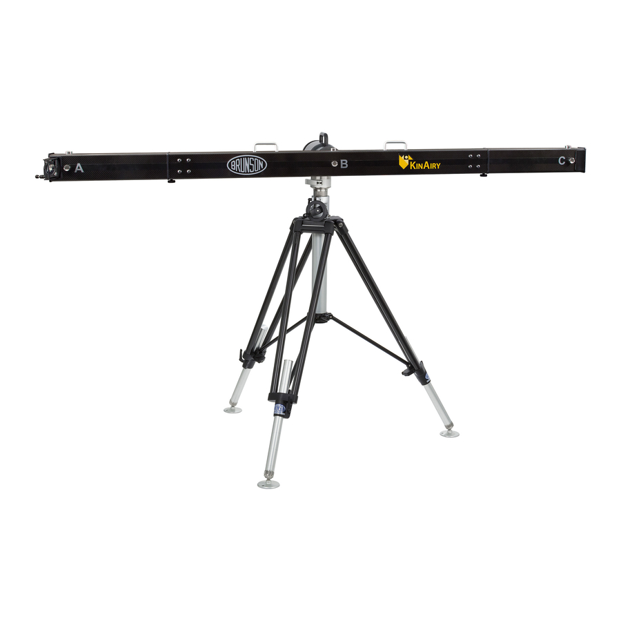
W H AT I S K I N A I R Y ? KinAiry is a laser tracker evaluation system, and gives easy access to the Interim Field Test for Laser Trackers as designed by the National Institute of Standards and Technology (NIST). It guides you step by step, providing confidence that your tracker is performing within expected norms. - Page 6 S YS T E M CO M P O N E N T S Positioner Mirror and Holder KinAiry Software Flashdrive Spanner Wrench ® EasyConnect Base Two Retroreflector Counterweights...
- Page 7 L E N G T H A R T I FAC T D E TA I L Back of Artifact Bar Side view of Positioner Carry Handles Target Nests Counterweight Nests Mirror Mount Mirror Adjustment Screws Ring Mount (on back) Hand Wheel (on back)
-
Page 8: Chapter 1: Getting Started
C H A P T E R O N E : G E T T I N G S TA R T E D Precautions: Safety • KinAiry is designed for use on flat, level floor surfaces. Deploying the length artifact on an unsuitable stand or on non-level surfaces increases the tipping hazard. - Page 9 Required Equipment The following items are required to run the NIST Interim Field Test with KinAiry. Not all of these items are included with your purchase of KinAiry. • KinAiry laser tracker evaluation system • Metrology stand (230 or M-Series recommended) •...
- Page 10 A dongle is shipped with its own key file, so if you purchased a dongle, simply plug it in at any time, and KinAiry will recognize the key file resident on the dongle. If you didn’t purchase a dongle, then you must follow the instructions...
-
Page 11: Hardware Assembly
After you have received your Key File, register it with KinAiry by selecting Register Key File from the Help menu. Navigate to the Key File and click Open. KinAiry will then validate and store the key. Once a valid key is registered, KinAiry will be ready to use. Hardware Assembly ®... - Page 12 Orient the positioner to allow Improper orientation of the Mount the artifact by placing the clearance between the stand positioner may cause contact ring brake into the slot on the face braces/legs and the length artifact between the artifact and stand of the positioner.
-
Page 13: Chapter 2: Software Features
My Tracker List Most tests performed by KinAiry require the user to select a tracker from My Tracker List. The list is accessible by selecting My Tracker List under the Tracker menu or from the tracker icon on the toolbar. Use the list to store identifying information for any tracker you wish to test. -
Page 14: Edit Default Mpe Coefficients
Edit Default Uncertainty Values A number of values have been identified as components of the uncertainty budget when using KinAiry to perform the NIST Interim Field Test. Some may be edited by the user (from the main menu select Tools , then Edit Default Uncertainty Values). -
Page 15: User Preferences
• Time — The test is to be completed within 60 minutes. This error will be triggered if data is altered beyond the allowable time limit. Times are not accessible from within the KinAiry software. Times can be viewed or edited in... -
Page 16: Pre-Test Setup Geometry Check
Before doing this positioning check (or the full KinAiry test, for that matter) be sure that the center of the coordinate system is defined at the tracker’s center (where the rotational axes meet). This is sometimes called “frame on instrument”... -
Page 17: The Four Data Tabs
The Four Data Tabs KinAiry has four tabs to display or edit information pertaining to any given test. These are the Define, Evaluation, Values, and Results tabs. Define Tab The Define tab is where an interim test begins. Here, you can define the test mode, and select parameters relevant to the chosen test mode. -
Page 18: Evaluation Tab
In some test modes, and when viewing an existing KinAiry test file, coordinate data is available and the Evaluation tab may be used as a viewer... -
Page 19: Values Tab
Values Tab The Values tab displays critical values pertaining to the current test, such as information for the current tracker under test. MPE coefficients and Uncertainty Budget terms are also displayed, and can be modified here (for the current test only). -
Page 20: Results Tab
Results Tab The Results tab displays an error graph visualizing results for the NIST Interim Field Test. The title contains the name of the test procedure, the make, model and serial number of the tracker under test, and the date the data was last modified. -
Page 21: Test Mode: Guided Walkthrough
• Indicating whether or not the tracker under evaluation has an interferometer When you click Start, KinAiry will bring the Evaluation tab forward. Navigate through the steps with the Next and Back buttons. Since no data is entered or imported in this test mode, no test information is displayed on the Values tab, and no error graph is generated on the Results tab. -
Page 22: Test Mode: Manual Data Entry
If the tracker you wish to test is not shown in the tracker used in test box, add it to the list by clicking on the My Tracker List icon on the toolbar or selecting My Tracker List from the Tracker menu. To begin the routine, click the Start button. KinAiry then brings the Evaluation tab forward. Follow the instructions and enter the data for each step. -
Page 23: Test Mode: Create Data Template
List icon on the toolbar or by selecting My Tracker List from the Tracker menu. To create the template, click the Start button. KinAiry will open a Save dialog in the default file folder location, with a suggested filename. You may use this... -
Page 24: Test Mode: Import Data File
After importing the data file, KinAiry will display the results of the test on the Results tab. Point coordinates are viewable and editable on the Evaluation tab. Save the KinAiry file for your records. -
Page 25: Caution
Seating the Kinematic Mounts KinAiry’s carbon composite length artifact rests on kinematic mounts. These mounts attach it to the aluminum support tube. As you face the artifact, you will see two sets of four socket cap screws. These are the two kinematic attachment points, and as you might expect, each one has a different internal configuration. - Page 26 For the AB mount, located between target nests A and For the BC mount, located between target nests B and B: Squeeze the carbon tube together with the aluminum C: Again, begin by squeezing the carbon and aluminum tube sufficiently to feel motion. Then release. The tubes together.
- Page 27 A P P E N D I X A : H O W TO E X P O R T D ATA P O I N T S F R O M B U I L D I T To prepare a data file for export to KinAiry using BuildIT, begin by taking the points in the same order as presented in KinAiry Guided Walkthrough mode.
- Page 28 After formatting click the Report button. A new Print Preview window will open. In the upper right hand corner of the print preview use the drop down shown to the left to export a CSV file. Import the CSV file using KinAiry software, Import Data File function.
- Page 29 A problem can arise if you open the exported *.csv file with Excel and then save it again before importing into KinAiry. If Excel opens a *.csv file and finds a cell which appears to contain a time value, but having digits to the right of a decimal point, it can default to a mm:ss.ddd format for that cell.
- Page 30 F R O M M E T R O LO G X 4 To prepare a text file for export to KinAiry using Metrolog, begin by taking the points in the same order as presented in KinAiry Guided Walkthrough mode.
- Page 31 The macro will prompt the user to select a folder location and enter a filename. It will then collect and sequentially log point data in a text file. The macro does not assist with the KinAiry test or allow for custom naming of each point or point set.
- Page 32 Do not include SA version or Axis Comments. Click OK to complete the export. The text file will contain many columns of data. Close the text file and import it using KinAiry software, Import Data File function.
- Page 33 F R O M V E R I S U R F X 8 To prepare a data file for export to KinAiry using Verisurf X8, begin by taking the points in the same order as presented in KinAiry Guided Walkthrough mode. Once recorded, select the points for export by checking the appropriate boxes in the feature tree on the left-hand side.
- Page 34 C A L I B R AT I O N P R O C E S S This KinAiry length artifact does not ship with a calibrated length certificate. The calibrated length is meant to be set in the field using the ranging system of the laser tracker. This procedure is relevant when the distance ranging performance of the laser tracker (i.e., straight IFM or straight ADM) is significantly more accurate than the angle...
- Page 35 Place the retroreflector in front of the mirror so that the tracker beam path is aimed at the center of the mirror. Break the beam path and remove the retroreflector to end tracking. The laser beam should now reflect off of the mirror. Place the retroreflector near target A in the path of the reflected beam, and allow the tracker to re-acquire the retroreflector.
- Page 36 Place the retroreflector in target nest C. The laser tracker will most likely not be pointing at the center of the retroreflector in this position. Manipulate the tip-tilt adjustments on the mirror mount to direct the beam path into the center of the retroreflector in target nest C.
- Page 37 If you have chosen to take several calibration shot repetitions, the KinAiry procedural guidance will explain the shot order to be: A, B, C, C, B, A, A, B, C, etc. Note that the KinAiry software expects points to be recorded in this same sequence when importing data.
- Page 38 A P P E N D I X H : T H E N I S T I N T E R I M T E S T P R O C E D U R E Standard tests of laser tracker performance have been developed (B89.4.19 , ISO 10360-10 , VDI/VDE 2617 Blatt 10 These tests use prescribed measurements under controlled laboratory conditions to determine or verify a laser tracker’s...
- Page 39 Table 1. NIST Interim Field Test orientations. Position Artifact Orientation Tracker Azimuth Vertical 0 ° Vertical 90 ° Horizontal 90 ° Horizontal 0 ° Horizontal with 0.5m vertical offset 0 ° Position 1 Position 2 Position 3 Position 4 Position 5...
- Page 40 IFM may have an R0 coefficient for each measurement mode. Care must be taken to test each mode for this error. KinAiry software will prompt an additional measurement step if a laser tracker is selected which operates in ADM and IFM mode.
- Page 41 A P P E N D I X I : T H E U N C E R TA I N T Y B U D G E T Uncertainty Budget Components Below are the uncertainty budget components for the calibration and measurement of the artifact used in the NIST Interim Field Test under field conditions.
- Page 42 repeat As a target reflector is repeatedly placed in a target nest on the artifact, variability can be observed. This variability can come from form of the sphere or nests, the support structure, or other physical behavior, as well as variability of the laser tracker discussed above.
- Page 43 Brunson Instrument Company service representative at least at a minimum of three – and a maximum of five – year intervals from the date of original shipment at the time of purchase from Brunson Instrument Company, and the instrument has not been subjected to alteration, rough handling, misuse, negligent use, fire damage, water damage or any other casualty.
- Page 44 R E F E R E N C E S ISO, ISO/DIS 10360-10: Geometrical product specifications (GPS)-acceptance and reverification tests of coordinate measuring systems (CMS): part 10. Laser trackers for measuring point-to-point distances, Geneva: International Standards Organization, 2013. ISO, ISO/TC 14253-1:2013 Geometrical product specifications (GPS) -- Inspection by measurement of workpieces and measuring equipment -- Part 1: Decision rules for proving conformity or nonconformity with specifications, Geneva: International Standards Organization, 2013.
- Page 45 WITH COUNCIL DIRECTIVE 2006/42/EC Date of Issue: 29 Sept, 2014 Document Ref: 18682 Rev 1 Directive: Machinery Directive 2006/42/EC Conforming Machinery: KinAiry Tracker Evaluation System Manufacturer: Brunson Instrument Company 8000 E. 23rd St. Kansas City MO 64129 Authorised Representative: Carl Baines 6 Micklehead Business Village St.
- Page 46 Brunson Instrument Company 8000 E 23rd Street Kansas City, MO 64129 www.brunson.us info@brunson.us Tel (816) 483-3187 Fax (816) 241-1945 © Copyright 2019 Brunson Instrument Company 5-28-19...
Need help?
Do you have a question about the KinAiry and is the answer not in the manual?
Questions and answers