
Subscribe to Our Youtube Channel
Summary of Contents for CIE 4871.MOT.V1
- Page 1 4871.MOT.V1 MINING OUTLET TESTER PATENT PENDING NO: AU2017902878 PRODUCT MANUAL Page | 1...
-
Page 2: Table Of Contents
Contents 1. SAFETY MEASURE ..............3 2. FEATURES ................6 Instrument Layout ............ 6 Test Function ............7 Applied Standards ............ 8 Features & Specification .......... 8 3. TESTING INSTRUCTIONS ............. 10 EARTH LEAKAGE LOCKOUT TEST (ELL) ....11 FROZEN CONTACT TEST (FC) ........13 EARTH CONTINUITY (EC) ........ -
Page 3: Safety Measure
This instrument must only be used by a competent and trained person with adequate certification, such as a licenced electrician. CIE will not accept liability for any damage or injury caused by misuse or non-compliance with the instructions. It is important to read and to understand the safety rules contained in the instructions provided. - Page 4 DANGER This instrument is to be used only for intended applications and under safe conditions, otherwise safety functions of this equipment will not work, and instrument damage or serious personal injury may occur. When conducting tests do not touch any exposed metalwork associated with the installation.
- Page 5 CAUTION For safety reasons only use accessories that are designed to be used with this instrument and recommended by CIE. Use a damp cloth and a mild detergent to clean the instrument. Do not use abrasive materials or solvents (eg. methylated spirits).
-
Page 6: Features
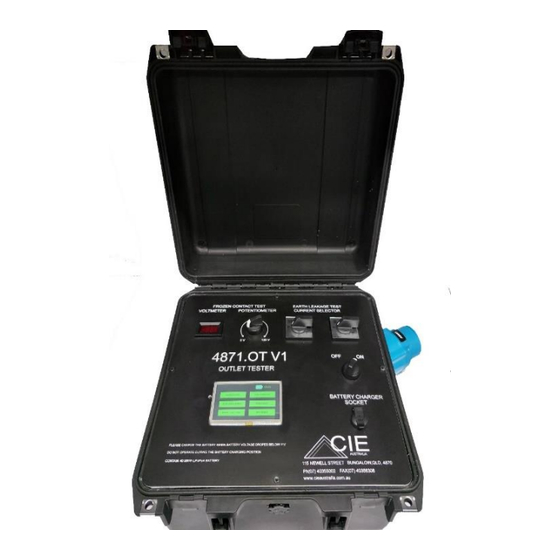
2. FEATURES Instrument Layout 1……… Instrument On/Off 2……… Battery Voltage Indication 3……… Main Control Touch Screen LCD 4……… Battery Charging socket 5……… Earth Leakage Current Selector Switch (1000V & 415V) Page | 6... -
Page 7: Test Function
Appliance Inlet DS3 1000V 3PE&2Aux 32A, where the test device will connect via test lead. Test Function 4871.MOT.V1 performs the following 6 test functions. Earth Leakage Lockout Frozen Contact Earth Continuity Remote Start and Stop Earth leakage with trip time... -
Page 8: Applied Standards
Safety: IEC 61010-1, CAT III(1000V), CAT IV 600V, IEC 60950 Protection degree: Operational IEC60529(IP54) Instrument in Storage 0529(IP64) Features & Specification 4871.MOT.V1 comprises the following features: • High speed • User friendly • Touch screen operation for all tests •... - Page 9 • Frozen contactor tests • Earth leakage lock out tests • Earth leakage test with 1000V, 415/240 and 110V via variety of different current levels. • Enclosed in a sturdy carry case for enhanced portability and durability • Light weight and long battery life for continuous operation (5 hour+) •...
-
Page 10: Testing Instructions
3. TESTING INSTRUCTIONS PRESS ENTER TO PROCEED TO MAIN TEST SCREEN Main Test Screen (Main Menu) Page | 10... -
Page 11: Earth Leakage Lockout Test (Ell)
EARTH LEAKAGE LOCKOUT TEST (ELL) PRESS this button to enter Earth Leakage Lockout Select your Pilot Mode according to the switchboard setup. Select Phase for ELL test Page | 11... - Page 12 Earth Leakage Lockout Main test screen From above test screen user can choose three different resistor values under selected phase to conduct the ELL test. This shows ELL test is On and also will display selected resistance and phase. In 9K and 900K continuity will be made healthy.
-
Page 13: Frozen Contact Test (Fc)
FROZEN CONTACT TEST (FC) DO NOT ENTER THIS TEST UNTIL THE TEST LEAD IS CONNECTED TO THE MOT AND THE OUTLET TO BE TESTED, AS THE MOT’S MARECHAL INLET WILL BE ENERGISED DURING THIS TEST. PRESS this button to enter the FC test screen DANGER INLET PINS ARE NOW LIVE After entering test Voltmeter and Potentiometer will activate for testing... - Page 14 Potentiometer will allow the user to select test voltage from 0 to 120 VAC which will show on the voltmeter. Turn voltage to 0 Volts and select a Phase. This test is live and will inject up to 120VAC. All workplace safety procedures should follow during this test.
-
Page 15: Earth Continuity (Ec)
EARTH CONTINUITY (EC) Press this button to enter Earth continuity Select your Pilot Mode according to the switchboard setup. Page | 15... - Page 16 Earth Continuity Test Screen Press Healthy to activate then press Open for Open Earth continuity test Press Healthy to rest then press short for Short Earth continuity test To exit test, press MAIN MENU Page | 16...
-
Page 17: Remote Start/Stop
REMOTE START/STOP PRESS this button to enter remote start Select your Pilot Mode according to the switchboard setup. Please note IPM relays do not support remote start in diode mode. Earth continuity/RTM to be healthy then Wait for Press start, wait for contactor to close then press Stop. -
Page 18: Earth Leakage Test (El)
EARTH LEAKAGE TEST (EL) PRESS this button to enter Earth Leakage test When conducting tests do not touch any exposed metalwork associated with the installation. In certain tests this metalwork may become live for the duration of test. Select remote or local start. Page | 18... - Page 19 Select earth continuity from Diode or RTM (refer to board manufacture), if there is no earth continuity, select Diode. Remote Local Close the contactor to energise the outlet under test. Earth Leakage phase selection test screen Page | 19...
- Page 20 Select only one current level. Incorrect selection can cause variation in trip time. Check correct voltage is selected. Check current and voltage for EL test before pressing enter to start the test. Once test finishes trip time will display in milliseconds.
- Page 21 If Earth leakage protection does not operate the test will time out. Repeat test at least twice per phase if an inconsistent reading is displayed. Repeat the test and discard any blatantly inconsistent readings. These occur occasionally and are caused by noise effecting the signal.
-
Page 22: Phase Information
PHASE INFORMATION PRESS this button to enter phase information Phase information will provide input phase to phase voltage and phase to earth voltage. This test requires main power supply to be on and contactor to be closed after appropriate earth continuity mode selection. - Page 23 Phase information Test screen Allow voltage snapshot to load then press phase rotation button to display rotation. If a change in rotation is made voltage must be updated first and then phase rotation button must be pressed again to read the current rotation and voltage.
-
Page 24: Servicing
4. SERVICING Charge the instrument when battery voltage falls below 11V. Low voltage can cause malfunction of this instrument. This instrument contains 3.2Ah LiFePo4 battery that requires a special charger. Do not use any other battery charger to charge this device other than the charger supplied.
Need help?
Do you have a question about the 4871.MOT.V1 and is the answer not in the manual?
Questions and answers