Table of Contents
Advertisement
Advertisement
Table of Contents

Summary of Contents for NURSE ROSIE RosieScan Bladder Scanner
- Page 1 Bladder Scanner USER MANUAL...
- Page 2 Forward Nurse Rosie Products, distributed by Life Systems, Inc. would like to thank you for your purchase of the RosieScan™ Bladder Scanner. Please read this manual carefully before using the RosieScan. Familiarize yourself with the features, methods of use, cautions and warnings, as well as any limitations of the scanner.
-
Page 3: Table Of Contents
Table of Contents Table of Contents Introduction ............................6 General Description ........................6 Primary Components ........................6 Intended Use ..........................6 Contraindication ........................... 7 Symbol Directory ........................... 7 Product Specification ..........................8 Main Technical Specifications ....................... 8 Accuracy Range ..........................8 Instructions for Environment Test .................... - Page 4 Powering On ..........................18 Ready Screen ..........................19 System Reset Screen ........................21 7.4.1 Time ............................ 21 7.4.2 Date ............................. 22 7.4.3 Print Images ........................22 7.4.4 Image Display: ........................22 7.4.5 Hospital ..........................23 7.4.6 Alarm ........................... 23 7.4.7 Sound ..........................
- Page 5 10.3 Service Guide ..........................41 Troubleshooting ..........................43 Quick Reference Guide ........................44 Appendix A ..............................45 Appendix B ..............................48 Warnings ............................. 48 Recharging and Discharging ......................48 Storage ............................49 Transportation ..........................49 Other Instructions ........................49 Appendix C ..............................50 Pre-Scan Image to the Left of Center ..................
-
Page 6: Introduction
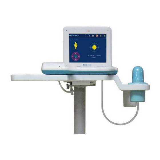
Introduction Introduction General Description The RosieScan (“Device”) is a noninvasive ultrasound device used to measure urinary bladder volume. During each scan, the RosieScan creates a three-dimensional image of the bladder. This image is then used to automatically calculate and display the urinary bladder volume. The results of the scan may be stored internally, printed using the on-board thermal printer or transferred to an external computer using a USB connection. -
Page 7: Contraindication
If any parts are missing please contact Life Systems using the contact information listed in the Foreword. Check to ensure that all components are connected properly and free of defect before turning on the RosieScan. Do not use if any component is missing or damaged. Cease use immediately and contact customer service if the RosieScan appears to be functioning abnormally in any way. -
Page 8: Product Specification
Product Specifications Product Specification Main Technical Specifications Transducer: 2.6MHz Probe: Mechanical Sector Scanning Detect depth : ≥140 mm; Host power supply: internal battery Battery: Voltage 7.4V (standard value), capacity: ≥4200mAh Charge the batteries for 3.5-4 hours for full charge. Fully charged batteries will provide 4 hours of sustained use Charger : Input voltage : AC 220V±10% 50±1HZ ,... -
Page 9: Instructions For Environment Test
Instructions for Environment Test The environmental testing for the device should be in accordance with requirements of GB/T 14710-2009 (Medical electrical equipment environmental requirement and test method) Sound Output The device is in accordance with GB16846-2008 and the announcement exemption for the public in chapter 6 of Requirement of medical ultrasound diagnosis device for its sound output (see Figure 2- Transducer frequency: 2.6MHz Fig 2-1 Technical Datasheet for... -
Page 10: System Overview
System Overview 3. System Overview Primary Components The system consists of two parts --hardware circuit and embedded software. 3.1.1 Hardware Components The hardware circuit consists of an embedded micro-controller system, B-mode transducer, B- mode signal processing module, B-mode signal A/D conversion module, Step-motor driving module, LED display system, print system, keyboard input, high speed USB screen and the power/battery management system. -
Page 11: Pictures And Descriptions
Figure3-2 Software Module Block Diagram Pictures and Descriptions The RosieScan consists of a main unit, ultrasonic probe and external thermal printer. RosieScan see Figure 3-3 Figure 3-3 Device LED Display 2. Control Panel 3. Printer 4. Power Light 5. Probe 6. - Page 12 Probe and USB Port see Figure 3-4 Figure 3-4 Ports Probe Port 2. USB Port 3D Probe see Figure 3-5 Figure 3-5 Ports Probe Cable 2. USB Plug 3. Probe Perspective Window Page...
-
Page 13: Circuit Diagram And Part List
Battery Box see Figure 3-6 Figure 3-6 Battery Box Battery Circuit Diagram and Part List Please contact Life Systems Inc. for circuit diagram, parts list and any other information pertaining to maintenance or repairs. THE USER SHOULD NOT DISASSEMBLE OR TRY TO REPAIR THIS DEVICE. Page... -
Page 14: Control Panel
Control Panel 4. Control Panel Figure 4-1 Control Panel Page... -
Page 15: Optimal Conditions
Optimal Conditions Optimal Conditions 5.1 For Use 1. Temperature range: +41~+105 F; 2. Relative humidity: ≤70%; 3. Atmospheric pressure: 700~1060 hPa; 4. Power supply of charger: AC 220V±10%,50Hz±1Hz; 5. Keep device away from strong electrical fields, strong magnetic fields and high-voltage equipment. -
Page 16: Installation
Installation Installation Installation Instructions 1. Put the device on a soft, flat surface. 2. Turn the main unit over so the bottom is facing up 3. To ensure that the battery is being installed correctly, confirm that the arrow on the unit ... - Page 17 Figure 6-2 Back view of main unit with battery in place Note: The device must be switched off before removing the battery. 8. To remove the battery, put the device on a soft, flat surface. Move the battery lock to the unlocked position, and then slowly pull the battery out of the unit.
-
Page 18: Navigation
Navigation Navigation Before Powering Up 1. Confirm that that battery is properly installed and locked 2. Confirm that the probe is properly installed 3. Confirm that the device is tightly secured on the stand (if applicable). Powering On To turn on the device, press the “POWER” key. Once turned on, the device will automatically check t h e battery level, printer, probe connection, memory capacity and screen. -
Page 19: Ready Screen
At the bottom right corner of the power on screen there will be two functional keys: functional key displays when self-checking fails, so touch the key or press the directional key on the control panel to enter “Ready” screen of system. You may touch with stylist pen or press Power button on the control panel to turn off the device. - Page 20 On the top of the Ready screen you will see a Status bar. The icons below may change depending on the device’s self-check results. Please consult the Figure 7-3 for the meaning of each icon. Please contact Life Systems Inc. if you have any questions. Icon Probe Printer...
-
Page 21: System Reset Screen
• Press key or touch to enter the system reset screen. You can touch the screen to select features you need to change or use the directional keys on the control panel. For example touch ”Scan Images” to choose between scanning 12 or 24 images. You must click on Save/Exit in order to save your changes and go to the pre-scan screen. -
Page 22: Date
◄ ► 2. Press the key to underling HH and then press the keys to move the underscore ▲ ▼ between HH/MM/SS (Hour/Minute/Seconds). Press the keys to adjust the time where the underscore is located. You can also use your stylist to touch HH, MM, or SS to change the time. -
Page 23: Hospital
▲ ▼ 2. Press the key to underscore the type of display image. Then press the keys to select “Gray Scale + Red Line” or “Gray Scale.” 3. Press the key to confirm the setting 7.4.5 Hospital ▲ ▼ 1. Select the “Hospital” option and press the keys or select “Hospital”... -
Page 24: Volume Calibration
3. Press the key or touch “Sound” again to save the setting. 7.4.8 Volume Calibration A “phantom bladder” will be needed for calibration. The phantom mimics a human bladder with a known volume. The phantom should be scanned and the measured volume should be the same as the phantoms standard volume. - Page 25 6. Scan Mode: ▲ / ▼ a. Press the keys or touch Scan Mode with the stylist pen b. Press the OK key or touch Scan ▲ / ▼ c. Press the keys or touch Human OR Phantom before selecting Scan Mode d.
-
Page 26: The Scan Screen
• Screen. • When selecting Phantom mode, Phantom will be displayed on the top left of the Ready screen. • Instructions for calibrating and correcting the scanner can be found in Appendix A The Scan Screen Figure7-11 displays a real time image in the pre-scan screen. The straight red line indicates the center of the area being scanned. - Page 27 Figure 7-12 Scanning Screen Do not disturb the device during scanning. The scan time is about 10 seconds for 12 images and 20 seconds for 24 images. The scanning progress will be displayed during the course of a scan (see Figure 7-12).
-
Page 28: The Scan Results Screen
The Scan Results Screen The scan results screen displays the results of the scan as shown in Figure7-14. Figure 7-14 Scan Results Screen 1. Press key or touch to return to the ready screen 2. Press key or touch to enter the save/edit screen ... -
Page 29: Gray Scale Results Screen
Gray Scale Results Screen ▲ Press key to enter t h e gray scale results screen. There are two settings in ‘Scan Page’ of the system. If 12 images were chosen, they will be display on two pages with 6 images on each page. If 24 images were chosen, they will be displayed on 4 pages with 6 images on each page. -
Page 30: The Save/Edit Screen
Figure 7-16 Scanned 2-Color Images Screen The Save/Edit Screen Figure 7-17 show the save/edit screen view. Figure 7-17 Save/Edit Screen Press key or touch to enter Save/Edit screen from the Scanned Results screen. How to operate in the Saved/Edit Screen with functional keys: ... -
Page 31: Browsing Historical Records
2. Press the OK key to confirm the selected character 3. Press the key before pressing to delete an unwanted character 4. Press the print key to save and return to Ready screen 5. Press the scan key to delete the saved information and return to the Ready screen How to operate in the Saved/Edit Screen with touch screen keys: 1. -
Page 32: Deleting Stored Records
a. The screen will display the patient’s ID, sex and measured volume record. The images from past scans will be displayed on the right under the patient ID. There will be 6 images displayed per screen. b. For example, if “This is 01/09” is displayed, “01” means this is one of nine total records that have been stored Press the key to print the current record being displayed... - Page 33 Page...
-
Page 34: Printing Results
7.10 Printing Results Scanned result can be printed immediately after performing a scan or recalled from the devices memory (if they were saved). User may select how many images to print on the Print Page (s e e Figure 7-27). Figure 7-27 Two Images Printed 7.11 Exporting Data to a PC... -
Page 35: Recharging The Battery
Figure 7-28 PC View Thermal Printer Instructions for changing the printer paper 1. Open the lid of printer as shown in Figure 7-29 2. Put the paper into paper box as shown in Figure 7-30 3. Pull out the paper about 5cm as shown in Figure 7-31 4. - Page 36 3. The green light will turn on after the battery is fully charged (It is suggested to charge the battery for at least 2 hours). 4. Disconnect the power between power supply and charger before removing the battery. Note: Do not leave the charger unsupervised while the battery is charging. Do not place the battery, adapter or charger near fire, heat, flammable and explosive materials.
-
Page 37: Clinical Application
Clinical Application Clinical Application Instructions for Use in a Clinical Setting 1. Patient should be in supine posture when a scan is performed. 2. Ultrasonic gel should be evenly applied to the acoustic window of the probe. 3. The probe should be placed on the human abdomen at about 2 cm above the pelvic bone. The probe should be slightly sloped towards to the head of patient, facing the direction of the bladder. -
Page 38: Images Of Invalid Scan Results
Images of Invalid Scan Results The following images (see Figure 8-1 to 8-10) are examples where the red edge and dark fluid area do not coincide. These are invalid scans and require the patient to be rescanned. Figure 8-1. Too large red edge line Figure 8-2 Too large red edge line Figure 8-3 Too large red edge line Figure 8-4 Too small red line... - Page 39 Note: If red edge is too large, then its volume will be too high, if red edge is too small, then its volume will be small, if red edge is not in the dark fluid area, its measured result will be small, and if the red edge is not in the dark fluid area, its scanned results will be ineffective.
-
Page 40: Transportation And Storage
Transportation and Storage Transportation and Storage Transportation The marks on the device packaging case conform to the requirement of GB/T191-2008 <Packaging and Storage Illustrated Marks>. Avoid rain, snow, inversion and collision during transportation. Storage Do not store the device for more than six months without removing it from its case and turning it on for at least 4 hours. -
Page 41: Maintenance And Service
Maintenance and Service Maintenance and Service 10.1 Maintenance for Probe 1. The probe is very fragile. It should not be dropped or struck against any other objects. Please turn off the scanning key and put it into the case for probe, during paused of scanning. - Page 42 2. SN of the device and the date of delivery; 3. Detailed problem description displayed on the screen. 4. The devices maintenance history, including the results of past repairs Service will be provided free of charge if the device is still under warranty. The device has an estimated life of 6 years (excluding the battery).
-
Page 43: Troubleshooting
Troubleshooting Troubleshooting 1. Ensure that the battery is inserted properly and has an adequate charge 2. Ensure that the connection between the device and the probe is secure 3. Check the printer’s connection and confirm that paper is inserted in the right direction. 4. -
Page 44: Quick Reference Guide
Quick Reference Guide Quick Reference Guide 1. Power On 2. Select Scanning Mode – Select - Male, Female or Pediatric <60 lbs 3. With Resident Supine – Apply gel (with no air bubbles) to midline approximately 1 inch (2-3 cm) above pubic symphysis 4. -
Page 45: Appendix A
Appendix A: RosieScan Calibration Appendix A Fix the probe on a holder. Make sure that the probe is placed vertically on the center of acoustic window of the phantom (standard phantom 128ml) See Figure A-1. *Note: If you are using a phantom that was not manufactured by the manufacturer of this device, please check the standard volume of your phantom before calibration Figure A-1 The Place of Probe... - Page 46 After switching on the device, enter the system reset screen by selecting Phantom in the Scan Mode before returning to Ready screen. Enter pre-scan state by pressing SCAN key (FigureA-3). Figure A-3 Pre-Scan Image Adjust the distance between probe and phantom; let the round dark area (target) be in the middle of fan-image in pre-scan.
- Page 47 If the measured result is not within 128±10ml, calibration is necessary. To begin, take 5 readings of the phantom and average the results. This will be the “mean value” that is to be entered in this formula: 128 (or standard value of phantom being used) – mean value = calibrating value Select Calibration in the system reset screen for the device calibration.
-
Page 48: Warnings
Appendix B: Battery Instructions Appendix B Warnings • Do not allow the battery to come into contact with sharp objects. • The battery should be stored in a clean environment away from sharp objects • The battery should not be perforated for any reason •... -
Page 49: Storage
• The temperature range is -20~60℃ (-4F~ 140F) during discharging. • The terminated voltage must be more than 5.6V when the battery is fully discharged. Storage • The environment temperature for Long time storage: -5~40 ℃ (23F~104F) • Relative humidity: <80% •... -
Page 50: Pre-Scan Image To The Left Of Center
Appendix C: Setting the Starting Location and Troubleshooting the Probe Appendix C There are 3 possible images on the screen in the pre-scanning. Pre-Scan Image to the Left of Center If the pre-scan image looks like Figure C-1, press the “-“button in the “Scanning Adjust” section in the system setting screen. -
Page 51: Pre-Scan Image To The Right Of Center
Figure C-4 ∠ Formula When 0° < ∠a < 15°, then 0 < a < 10 When 15°< ∠a < 30°,10 < a < 20; When 30°< ∠a < 45°,20 < a < 30; When 45°< ∠a < 60°,30 < a < 40; Return to pre-scan mode to check the red line and the image’s position. - Page 52 Formula: When 0° < ∠a < 15°, then 0 < a < 10 When 15°< ∠a < 30°,10 < a < 20; When 30°< ∠a < 45°,20 < a < 30; When 45°< ∠a < 60°,30 < a < 40; Return to pre-scan mode to check the red line and the image’s position.
-
Page 53: Electromagnetic Emissions
Appendix D: Guidance and Manufacturer’s Declaration Appendix D D.1 Electromagnetic Emissions Guidance and manufacturer’s declaration: electromagnetic emissions The PBSV4.1 bladder scanner is intended for use in the electromagnetic environment specified below. The customer or the user of the SECP-II should assure that it is used in such an environment. Emissions test Compliance Electromagnetic environment - guidance... -
Page 54: Electromagnetic Immunity
Electromagnetic Immunity Guidance and manufacturer’s declaration: electromagnetic immunity is intended for use in the electromagnetic environment specified PBSV4.1 bladder scanner below. The customer or the user of the should assure that it is used in such an PBSV4.1 bladder scanner environment. - Page 55 Guidance and manufacturer’s declaration: electromagnetic immunity The PBSV4.1 bladder scanner is intended for use in the electromagnetic environment specified below. The customer or the user of the PBSV4.1 bladder scanner should assure that it is used in such an environment. Compliance Electromagnetic Immunity test...
- Page 56 Recommended separation distances between portable and mobile RF communications equipment and the PBSV4.1 bladder scanner is intended for use in an electromagnetic environment in which PBSV4.1 bladder scanner radiated RF disturbances are controlled. The customer or the user of the PBSV4.1 bladder can help prevent electromagnetic interference by maintaining a minimum distance scanner...
Need help?
Do you have a question about the RosieScan Bladder Scanner and is the answer not in the manual?
Questions and answers
Unable to scan. No scan options
There are no scan options available on the NURSE ROSIE Bladder Scanner if the device is not properly set up. Before scanning, the system must be turned on, gender must be selected, and the probe must be correctly connected and placed. If these steps are not completed, scan options may not appear.
This answer is automatically generated