Table of Contents
Advertisement
Quick Links
CMUip-2212
ATCC Cabinet Monitor Unit
Operations Manual
THIS MANUAL CONTAINS TECHNICAL INFORMATION FOR
THE CMUip-2212-HV, CMUip-2212-LV, and CMUip-2212-VHV
ATC CABINET MONITOR UNIT.
Firmware Version 2.0 (vXX20) Issue J PCB
REVISION: MAY 2019
pn 888-2212-001
- NOTE -
EDI ECCOM SOFTWARE MUST BE UPDATED TO VERSION 4.5 OR HIGHER.
EDI MONITORKEY SOFTWARE MUST BE UPDATED TO VERSION 2.6 OR HIGHER.
EDI SOFTWARE IS AVAILABLE AT WWW.EDITRAFFIC.COM
Advertisement
Table of Contents

Subscribe to Our Youtube Channel
Summary of Contents for EDI CMUip-2212 Series
- Page 1 Firmware Version 2.0 (vXX20) Issue J PCB REVISION: MAY 2019 pn 888-2212-001 - NOTE - EDI ECCOM SOFTWARE MUST BE UPDATED TO VERSION 4.5 OR HIGHER. EDI MONITORKEY SOFTWARE MUST BE UPDATED TO VERSION 2.6 OR HIGHER. EDI SOFTWARE IS AVAILABLE AT WWW.EDITRAFFIC.COM...
- Page 2 THE CMUip-2212 SERIES CABINET MONITOR UNIT IS DESIGNED AND MANUFACTURED IN THE USA BY EBERLE DESIGN INC. PHOENIX, ARIZONA. EDI IS CERTIFIED TO ISO 9001:2016 QUALITY SYSTEMS STANDARDS. IPACK AND LEDguard ARE REGISTERED TRADEMARKS OF EDI. DATAKEY AND KEYCEPTICLE ARE TRADEMARKS OF DATAKEY INC. INFORMATION CONTAINED HEREIN IS PROPRIETARY TECHNICAL INFORMATION OF EBERLE DESIGN INC.
-
Page 3: Table Of Contents
Table of Contents Section 1 GENERAL ......................1 1.1 Overview ........................ 1 1.2 Channel Configuration .................... 1 1.3 High Density Switch Pack (HDSP)................1 1.4 High Density Flasher Unit (HDFU) ................2 1.5 CMUip-2212 Programming ..................2 1.6 Detailed CMU Status ....................2 1.6.1 ECcom Software Interface ................ - Page 4 2.16.2.1 Conflict .....................12 2.16.2.2 Red Fail ....................12 2.16.2.3 Dual Indication ..................12 2.16.2.4 Minimum Yellow Clearance ...............13 2.16.2.5 Yellow Plus Red Clearance ...............13 2.16.3 Red and Yellow Input Enable ..............13 2.16.4 Flash Rate Detection ..................13 2.16.5 FYA Yellow Trap Conflict Detection............13 Section 3 INPUT SIGNALS ....................15 ®...
- Page 5 6.1.1 CMUip-2212-HV & CMUip-2212-VHV Pin List ..........25 6.1.2 CMUip-2212-LV Pin List ................25 6.2 CMUip-2212 Ethernet LAN Port ................26 6.2.1 Ethernet LAN Cable ..................26...
-
Page 6: Section 1 General
CMUip-2212 Cabinet Monitor Unit Operations Manual Section 1 GENERAL 1.1 OVERVIEW The model CMUip-2212 Cabinet Monitor Unit (CMUip-2212) is the principle part of the ATC Traffic Control Cabinet Monitoring System. It is resident in the Output Assembly and communicates with the High Density Switch Packs (HDSP) located in each Output Assembly via Serial Bus #3. -
Page 7: High Density Flasher Unit (Hdfu)
Historical event logs and signal sequence logs are also provided. See the EDI ECcom Operation Manual (pn 888-1000-001) for further details. The ECcom Signal Monitor Communications software can be obtained from the Eberle Design web site at www.EDItraffic.com. -
Page 8: Serial Bus #1
CMUip-2212 Cabinet Monitor Unit Operations Manual 1.7 SERIAL BUS #1 Serial Bus #1 provides a communication path between the CMUip-2212 to the ATC. The communications between the ATC and the CMUip-2212 plays an integral role in ensuring safe and proper operation of the cabinet equipment as well as providing important diagnostic functions used for trouble shooting malfunctioning equipment. -
Page 9: Failed State Action (Lfsa, Lfsa-R, Nfsa)
CMUip-2212 Cabinet Monitor Unit Operations Manual 1.9 FAILED STATE ACTION (LFSA, LFSA-R, NFSA) When triggered by the detection of a fault condition that exists longer than the minimum defined period, the CMUip-2212 will enter the Failed State Action (fault) mode causing the OUTPUT relay to de-energize and the contacts on the OUTPUT NO pins to open. -
Page 10: Section 2 Monitor Functions
CMUip-2212 Cabinet Monitor Unit Operations Manual Section 2 MONITOR FUNCTIONS 2.1 CABINET POWER SUPPLY MONITOR The CMUip-2212 will sense the Cabinet +48VDC, +24VDC and +12VDC power supply sources. The CMUip-2212 will also sense the Cabinet +24VDC state as reported by each HDSP. -
Page 11: Type 62 Fsa Message
CMUip-2212 Cabinet Monitor Unit Operations Manual 2.4 TYPE 62 FSA MESSAGE If the “N” bit is set in a Type 62 message, the CMUip-2212 will react by causing a NFSA. The NFSA will remain until the receipt of a Message 62 with the “N” bit cleared or until the CMUip-2212 is reset by a Unit Reset or CMUip-2212 Power Fail. -
Page 12: Yellow Plus Red Clearance Monitor
CMUip-2212 Cabinet Monitor Unit Operations Manual Minimum Yellow Change interval monitoring will be disabled when the MC COIL STATUS input is not active. There is programming in the Datakey to disable Minimum Yellow Change interval monitoring on a per channel basis. 2.8 YELLOW PLUS RED CLEARANCE MONITOR The CMUip-2212 will verify that the Yellow Change plus Red Clearance interval between the end of an active Green/Walk signal and the beginning of the next conflicting... -
Page 13: Cmu Power Failure
CMUip-2212 Cabinet Monitor Unit Operations Manual 2.12 CMU POWER FAILURE The CMUip-2212 will monitor the MAINS input and the NRESET and POWERDOWN cabinet control inputs to determine a CMU Power Failure response. The POWERDOWN signal in the False (low) state indicates loss of Mains voltage in the ATC. A CMU Power Failure will be recognized when both the POWERDOWN and NRESET signals are False (low) for greater than 100 ms or the MAINS voltage is below the dropout level. -
Page 14: Field Check Mode
CMUip-2212 Cabinet Monitor Unit Operations Manual The Field Output Check function is enabled for each channel input individually and provides two modes of operation, Field Check Mode and Field Check Status. 2.13.1 FIELD CHECK MODE The CMUip-2212 will compare the active states of the field signals with the states reported by the ATC in the Type 81 (67) frame. -
Page 15: Datakey Memory Diagnostic
CMUip-2212 Cabinet Monitor Unit Operations Manual 2.14.3 DATAKEY MEMORY DIAGNOSTIC This test will verify whether the non-volatile Datakey contains valid data. The routine will perform a check on each nonvolatile memory element at power-up and whenever read and make a comparison with a 16 bit Frame Check Sequence (FCS) procedure defined in clause 4.6.2 of ISO/IEC 3309. -
Page 16: Recurrent Pulse Detection Disable
The CMUip-2212 firmware release vXX20 or higher must be installed in the CMU to provide support for eight FYA approaches. ECcom and MonitorKey software must be updated to v4.5+ and v2.6+ respectively. Consult the EDI factory for further details. For monitoring purposes an FYA approach is logically defined as a four input “logical channel”... -
Page 17: Conflict
CMUip-2212 Cabinet Monitor Unit Operations Manual For an FYA channel pair the fault configuration parameters are applied to the Primary channel with three inputs, Ra-Ya-fYa. The fault configuration parameters programmed for the Sparse channel of the FYA pair with only one input, Ga, only affects the sparse channel and not the Primary channel, and should be used only when the RY INPUT Enable option is Enabled for that channel. -
Page 18: Minimum Yellow Clearance
CMUip-2212 Cabinet Monitor Unit Operations Manual simultaneously for the Dual Indication fault response time. The fault status will be displayed for both channels of the FYA pair when the sparse channel input (Ga) is active. If the RG, RY, or GY Dual Indication function is enabled and the RY Input option is enabled for the sparse channel (Ga), then a Dual Indication fault will occur if any two or more of the Red, Yellow, or Green inputs are active simultaneously on the sparse channel for the Dual Indication fault response time. - Page 19 CMUip-2212 Cabinet Monitor Unit Operations Manual the solid yellow arrow clearance while the Opposing Through channel is still showing a green ball. When the FYA Yellow Trap Conflict condition is detected, the CMUip-2212 will enter the fault mode, transfer the OUTPUT relay contacts to the Fault position, and display the “CONFtrap”...
-
Page 20: Section 3 Input Signals
CMUip-2212 Cabinet Monitor Unit Operations Manual Section 3 INPUT SIGNALS ® 3.1 LEDGUARD FIELD SIGNAL SENSING ® The CMUip-2212 uses a technique called LEDguard that is designed to better monitor the characteristics of LED based signal loads. Each field signal input is measured and compared to both a high threshold and a low threshold value to determine On / Off status. -
Page 21: Ftr Coil Drive Status
CMUip-2212 Cabinet Monitor Unit Operations Manual Section 5.1) on this input indicates the Signal Bus is powering the load switches. The CMUip-2212 will report the state of this input in the Type 209 (195) frame. 3.3.4 FTR COIL DRIVE STATUS The cabinet should be wired such that the FTR COIL DRIVE STATUS input is connected to the FTR COIL DRIVE signal in the SIGNAL POWER BUS. -
Page 22: Serial Bus #1 Disable Input
CMUip-2212 Cabinet Monitor Unit Operations Manual The default address for the CMU is 0x0F. If multiple CMU units are not installed on Serial Bus #1 these inputs should be left in the False (open) state. 3.7 SERIAL BUS #1 DISABLE INPUT The SERIAL BUS #1 DISABLE input is used to prevent a Serial Bus #1 Error when communications from the ATC is not active. -
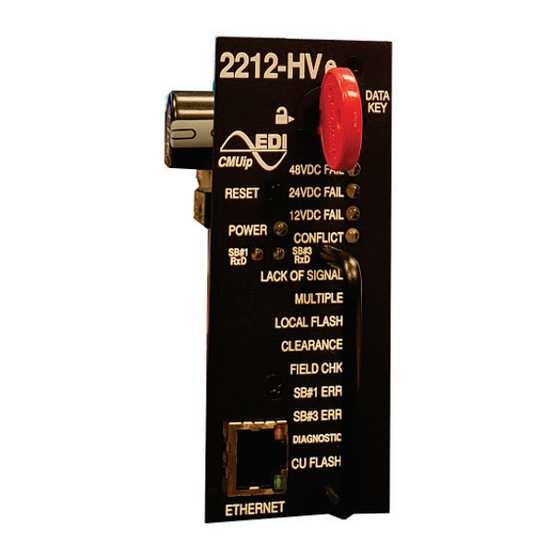
Page 23: Section 4 Front Panel Description
CMUip-2212 Cabinet Monitor Unit Operations Manual Section 4 FRONT PANEL DESCRIPTION 4.1 INDICATORS 4.1.1 POWER INDICATOR A green POWER indicator will illuminate to indicate MAINS voltage is proper. It will flash at a 2 Hz rate when the MAINS input of the CMU is less than the Dropout voltage (see Section 5.1). -
Page 24: Clearance Indicator
CMUip-2212 Cabinet Monitor Unit Operations Manual During Local Flash Status mode, the Auxiliary Display Unit (ADU) will display the active field signals. This can be helpful to verify that flash mode is active on all outputs appropriately. Note that a short time delay will be introduced to the ADU display in this mode. - Page 25 CMUip-2212 Cabinet Monitor Unit Operations Manual The Datakey can be removed without the CMUip-2212 placing the cabinet into flash only if the Front Door is Open. When a Datakey is removed while the power is applied to the CMU-2212, the CMUip-2212 will continue to use the parameters from the removed Datakey until Reset is applied, a new Datakey is installed, or a power-up cycle occurs.
-
Page 26: Section 5 Specifications
CMUip-2212 Cabinet Monitor Unit Operations Manual Section 5 SPECIFICATIONS 5.1 ELECTRICAL 5.1.1 CMU-2212-HV Power Requirements Operating Line Voltage ................... 75 to 135 Vac Operating Line Frequency ..................60 ± 3 Hz Power Consumption ................10 Watts Maximum AC Field Signals LEDguard Field Signal High Levels Active ................. -
Page 27: Cmu-2212-Lv
CMUip-2212 Cabinet Monitor Unit Operations Manual 5.1.2 CMU-2212-LV Power Requirements Operating Mains Voltage .................. 35 to 60 Vdc Operating Mains Nominal Voltage ................48 Vdc Power Consumption ................10 Watts Maximum DC Field Signals LEDguard Field Signal High Levels Active ................. greater than 43 Vrms Not Active ................ -
Page 28: Timing
CMUip-2212 Cabinet Monitor Unit Operations Manual Not Active ................less than 30 Vrms AC Control Monitors MC Secondary Status Active ..................greater than 166 Vrms Not Active ..................less than 154 Vrms DC Control Monitors Local Flash Status, MC Coil Status, FTR Coil Drive, CB Trip Status Active ................... -
Page 29: Mechanical
CMUip-2212 Cabinet Monitor Unit Operations Manual Fault ..................greater than 1500 ms No Fault ..................less than 1200 ms Typical ......................1350 ms Yellow Clearance Fault ....................less than 2600 ms No Fault ..................greater than 2800 ms Typical ......................2700 ms Yellow Plus Red Clearance Fault .................... -
Page 30: Section 6 Connector Assignments
CMUip-2212 Cabinet Monitor Unit Operations Manual Section 6 CONNECTOR ASSIGNMENTS 6.1 MAIN DIN CONNECTOR The CMUip-2212 main connector is a two row DIN 4161264 Header Type. 6.1.1 CMUIP-2212-HV & CMUIP-2212-VHV PIN LIST Pin # Function Pin # Function +24VDC Monitor Reserved +12VDC Monitor External Test Reset... - Page 31 Note: Output Relay NO is open during FSA (de-energized). 6.2 CMUIP-2212 ETHERNET LAN PORT The network port parameters can be set or changed using the EDI ECcom software. The network port parameters can also be configured in the Datakey. See the EDI ECcom Operation Manual (pn 888-1000-001) and MonitorKey Operations Manual (pn 888- 1212-001) for details.
Need help?
Do you have a question about the CMUip-2212 Series and is the answer not in the manual?
Questions and answers