
Related Manuals for Econex AB1 Series


Summary of Contents for Econex AB1 Series
-
Page 1: Table Of Contents
ELECTRIC ROTARY GEAR MOTOR SERIES AB1 INSTALLATION AND OPERATING INSTRUCTIONS ENERAL EATURES ECHNICAL NSTALLATION IRING ABLE ONNECTIONS UXILIARY ICROSWITCHES EEDBACK OTENTIOMETER ONTROL TATION DJUSTMENTS 10. O PERATING 11. M AINTENANCE 12. R EPLACEMENT 1 of 10... -
Page 2: General Features
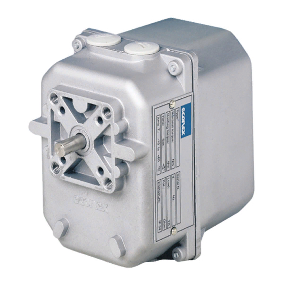
GENERAL FEATURES Electric rotary gear motors of series AB1 have been newly conceived and specially designed to be installed on residential and industrial combustion systems. They are particularly suitable for control and regulation of modulating disc valves, butterfly valves, dampers and other fluid regulation systems requiring control of position angle within 90°... -
Page 3: Installation
INSTALLATION Make sure that all operating data indicated on gear motor plate correspond to the ones of the systems. When installing the gear motor make sure that there is sufficient clearance above the gear cover and that it is easily accessible in order to perform wiring and endswitches' adjustment. -
Page 4: Wiring
WIRING After having installed AB1 gear motor and before fastening it mechanically to the device it has to operate, proceed with wiring and earthing. Wiring diagrams are reported in the attached technical bulletin and on the plate inside the cover. WARNING! Before servicing make sure, that power supply is disconnected by means of the two-pole-switch [phase and neutral];... -
Page 5: Cable Connections
CABLE CONNECTIONS The wiring schemes refer to the gear motor in position “closed” [0°]. Without manual/automatic control station. ERMINAL BOARD Terminal earthing Terminal 1 N = neutral Terminal 2 by tension the gear motor shaft rotates clockwise [closes] Terminal 3 by tension the gear motor shaft rotates counter clockwise [opens] Terminal 16... - Page 6 With manual/automatic control station ERMINAL BOARD Terminal earthing Terminal 1 N = neutral Terminal 2 by tension the gear motor shaft rotates clockwise [closes] Terminal 3 by tension the gear motor shaft rotates counter clockwise [opens] Terminal 4 for manual electric control Terminal 16 answer signal when the gear motor reaches the position “open”...
-
Page 7: Auxiliary Microswitches
AUXILIARY MICROSWITCHES On request, AB1 gear motor can be supplied with 2 auxiliary microswitches, which can be adjusted in any position. Microswitches are voltage-free. Contact rating is about 5 A/250 with Ohm load and about 1 A/250 with inductive load. For adjusting the cams of auxiliary microswitches, proceed as for cams of endswitches as indicated in paragraph 9.1 chapter 9 “SETTINGS”. -
Page 8: Adjustments
ADJUSTMENTS Endswitches As already reported in chapter 4 paragraph 4.3 the AB1 electric rotary gear motor is supplied by the factory with adjustment foreseen for a 90° rotation angle. If higher or lower than 90° rotation angles are requested, proceed as follows: 9.1.1 Disconnect the operating lever system of the gear motor shaft and remove the cover. - Page 9 9.1.9 Once all adjustments have been carried out return the key inside the AB1 gear motor and reinstall the cover by fastening the 4 screws. 9.1.10 Reinstall the control lever system of the AB1 gear motor and test functioning of the whole system. Potentiometer/s 9.2.1 The potentiometer shaft is frictioned and is accessible from the upper side inside the gear motor.
-
Page 10: Operating
10. OPERATING After installation and adjustment of the control lever system check that switch and wiring of the circuit are correct. Check that the AB1 rotary gear motor duly controls the device it is meant for. Check that the AB1 rotary gear motor runs in accordance with the given manual input. Check that the AB1 gear motor, the lever system and the controlled device are mechanically connected in a correct and safe way.
Need help?
Do you have a question about the AB1 Series and is the answer not in the manual?
Questions and answers
HelloIs this model capable of receiving analog signals?
Yes, the Econex AB1 Series is capable of receiving analog signals through available potentiometers with values of 150, 1000, or 2500 Ohm.
This answer is automatically generated