Table of Contents
Advertisement
Quick Links
Advertisement
Table of Contents

Subscribe to Our Youtube Channel
Related Manuals for Stanley GW1200

Summary of Contents for Stanley GW1200
- Page 1 GW1200 GATEWAY INSTALLATION & CONFIGURATION GUIDE...
- Page 2 This document is confidential and proprietary to STANLEY Healthcare and is not to be distributed to any persons other than licensed AeroScout Visibility System users or other persons appointed in writing by STANLEY Healthcare.
-
Page 3: Table Of Contents
Network and Power Connections to the GW1200 Gateway ........... 8 Resetting the GW1200 Gateway IP Address ..............11 GW1200 Naming Convention ..................12 Adding & Configuring the GW1200 via AeroScout Engine Manager (AEM) ....13 Updating Firmware – Gateways ................... 14 Mounting the Gateway ....................15 Fixing the Controller to a Floating Ceiling: .............. -
Page 4: Gw1200 Gateway
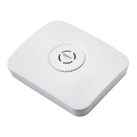
GW1200 Gateway Installation & Configuration Guide GW1200 Gateway The GW1200 Gateway is a component of STANLEY Healthcare’s suite of solutions based on Wi-Fi technology, enabling hospital-wide protection of patients and infants. The Gateway is a 2.4 GHz receiver. It receives transmission messages from Hugs Wi-Fi Tags and relays the messages to the Location Engine. -
Page 5: Gw1200 Features
The device supports remote programming, monitoring, and software updates by the AeroScout Location Engine. Continuous Gateway Supervision The GW1200 Gateway device status is monitored at all times by the AeroScout Location Engine. MobileView generates an alert if communication with the Gateway is compromised. -
Page 6: Led Status Indicators
GW1200 Gateway Installation & Configuration Guide LED Status Indicators The GW1200 Gateway has a single LED that changes color based on the device status as follows: Constant Green: The Gateway is on and working correctly • Constant Orange: Gateway failure or network down •... -
Page 7: Connector Panel
(#1) Ethernet LAN Connection: RJ-45 connector. In a configuration with a physical Ethernet cable connection to the LAN, the network cable is attached here. The GW1200 supports 100 Mb Full duplex communications. The Ethernet Network Switch must be configured to Auto Negotiation mode for the Gateway to operate at 100 (#2) Power Jack: Accepts an input voltage of 24-48V DC. -
Page 8: Network And Power Connections To The Gw1200 Gateway
Connect a 24 to 48 VDC power source direct to the Gateway’s power jack. The GW1200 requires approximately 8 W of power. When connecting a Gateway to a direct power source with one of the above options, verify that the provided power Note level is sufficient. - Page 9 These adapters convert 110 VAC or 220 VAC to 48 VDC. Figure 4: 110/220 VAC to 48 VDC Adapter The adapter is connected to the GW1200 Gateway power jack. The network must be connected separately to the Gateway LAN connector.
- Page 10 GW1200 Gateway Installation & Configuration Guide Power Connection Summary The following table summarizes the power connection options: Power Supply Input Output Max. Available Maximum # of Current Exciters with One Power Source PoE single port 100-240 48 VDC 0.32 A(1) 15.4 W...
-
Page 11: Resetting The Gw1200 Gateway Ip Address
GW1200 Gateway Installation & Configuration Guide Resetting the GW1200 Gateway IP Address The GW1200 Gateway IP address can be reset to the factory default value of 192.168.1.178. The Gateway does not support DHCP; requiring all device addresses to be manually configured. -
Page 12: Gw1200 Naming Convention
GW1200 Gateway Installation & Configuration Guide GW1200 Naming Convention In line with our recommended best practice, when configuring the GW1200 Gateways in the AeroScout Location Engine, use recognizable names for the GW1200 Gateways as the Gateway names are used in the alert distribution, and should provide clear... -
Page 13: Adding & Configuring The Gw1200 Via Aeroscout Engine Manager (Aem)
Adding & Configuring the GW1200 via AeroScout Engine Manager (AEM) GW1200 Gateways are manually added and configured to appear on the map as an Exciter. Multiple Gateways can be added to the Location Engine using the Load Devices option on the Repository tab, or the Scanning for Devices option after setting their IP addresses and connecting them to the network. -
Page 14: Updating Firmware - Gateways
GW1200 Gateway Installation & Configuration Guide Updating Firmware – Gateways Updating the Firmware of GW1200 Gateways is performed in the Engine Manager. For more information refer to the AeroScout Location Engine Deployment Guide – Upload Exciter Firmware section. -
Page 15: Mounting The Gateway
GW1200 Gateway Installation & Configuration Guide Mounting the Gateway Position and mount each GW1200 Gateway according to the site survey recommendations. Fixing the Controller to a Floating Ceiling: Mounting on a Wide grid with Flush Tiles For this mounting option no mounting kit is required. Attach the device to the false ceiling using the ceiling mounts located on the bottom casing of the device Align the Mounting clips with the wide grid. - Page 16 GW1200 Gateway Installation & Configuration Guide Figure 6: Correct Complete Mounting Position Mounting Off-Grid For this mounting option the following parts from the Heavy Duty, Off Grid, Exciter kit (EXAC-HDUTY-1000) are required: Mounting Part Part Name Quantity Image Letter Mounting Adaptor ¼”...
- Page 17 GW1200 Gateway Installation & Configuration Guide Cut the Mounting Adaptor (A) so that only Section # 1 remains. Use Mount Adaptor part marked with “<= 1 =>” Step 2 – Fasten 2 Screws (E) on the 512HD Bracket (D) with 1 Flat Washer (H) and 1 Spring Washer (I).
- Page 18 GW1200 Gateway Installation & Configuration Guide Mount the Assembled 512HD Bracket (D) on the tile. Fix in place 2 Nuts (G) on each of the Screws (E) leaving enough screw length (2/5” or 10mm) to mount the Adaptor. Mount the Adaptor using 2 Nuts (G) using a 7/16” nut driver.
- Page 19 GW1200 Gateway Installation & Configuration Guide Figure 7: Correct Complete Mounting Position...
- Page 20 GW1200 Gateway Installation & Configuration Guide Mounting on a Narrow-Grid T-Bar For this mounting option the following parts from the Standard Exciter Mounting kit (EXAC-STD-1000) are required: Part Letter Part Name Quantity Image Mounting Adaptor Narrow Grid Clip- 9/16” Clip with #8 Stud #8-32 Hex Nyloc Nut Cut the Mounting Adaptor (A) so that only Section # 1 remains.
- Page 21 GW1200 Gateway Installation & Configuration Guide Attach the Grid Clips (C) with Mount Adaptor (A) onto the ceiling grid. (Push the clips against the grid and twist them until they lock) (turn clockwise). Fasten the Adaptor (A) to the Clips (C) by tightening Nuts (J) into their final position using a 11/32"...
- Page 22 GW1200 Gateway Installation & Configuration Guide Figure 8: Correct Complete Mounting Position...
- Page 23 GW1200 Gateway Installation & Configuration Guide Mounting on a Wide Grid with Recessed Tiles For this mounting option the following parts from the Standard Exciter Mounting kit (EXAC-STD-1000) are required: Part Letter Part Name Quantity Image Mounting Adaptor Wide Grid Clip-15/16”...
- Page 24 GW1200 Gateway Installation & Configuration Guide Attach the Grid Clips (C) with Mount Adaptor (A) onto the ceiling grid. (Push the clips against the grid and twist them until they lock). Fasten the Clip’s stud (B) against the grid using a flat screwdriver (turn clockwise).
- Page 25 GW1200 Gateway Installation & Configuration Guide Figure 9: Correct Complete Mounting Position Mounting on a Slotted Grid For this mounting option the following parts from the Standard Exciter Mounting kit (EXAC-STD-1000) are required: Part Letter Part Name Quantity Image Mounting Adaptor For Slotted Grid- 1/4"x0.625"...
- Page 26 GW1200 Gateway Installation & Configuration Guide Use Mount Adaptor part marked with “<= 1 =>” Assemble the Screws (F) on the Adaptor. Lock each Screw (F) with Hex Nut (G) *Nuts should be loose at this step to allow easy insertion into the slotted grid.
- Page 27 Mounting the Gateway on a Wall While not normal practice, there may be occasions, particularly in older facilities where the ceilings are already congested, when wall mounting of the GW1200 Gateway may be the only viable option. The Gateway is shipped with a mounting template which can be used to measure the holes for mounting the Gateway on a wall.
- Page 28 Anchor the screws into the wall, leaving 10mm of each of the screws exposed. Use appropriate screws and or anchoring plugs. Mount the Gateway with the STANLEY Healthcare logo facing up, onto the 4 screws. The Gateway's back panel has 4 mounting brackets for this purpose.
-
Page 29: Gw1200 And Accessories Model Numbers
GW1200 Gateway Installation & Configuration Guide GW1200 and Accessories Model Numbers Product Description GW1200 GW-1200 GW1200 Gateway. Includes 48V DC input, Gateway Ethernet and PoE interface Power Supply APD-047-U (US) AC/DC adaptor 45W 48 V/1.0A 90-264VAC for EX2000B, EX4200, EX5000, EX5200 Exciters,... -
Page 30: Gw1200 Specifications
GW1200 Gateway Installation & Configuration Guide GW1200 Specifications Product Marketing Name (PMN) GW1200 Gateway • Physical and Mechanical Dimensions: 245 mm X 200 mm X 60 mm (9.6 in x 7.9 in x 2.4 in) • Weight: 865 g (31oz) •... -
Page 31: Regulatory Compliance & Warranty
GW1200 Gateway Installation & Configuration Guide Regulatory Compliance & Warranty 47 CFR Part 15, Class B Device This device complies with part 15 of the FCC Rules. Operation is subject to the following two conditions: (1) This device may not cause harmful interference, and (2) this device must accept any interference received, including interference that may cause undesired operation. -
Page 32: Rohs
GW1200 Gateway Installation & Configuration Guide This device complies with Industry Canada license-exempt RSS standard(s). Operation is subject to the following two conditions: (1) this device may not cause interference, and (2) this device must accept any interference, including interference that may cause undesired operation of the device. - Page 33 The date of shipment of the Hardware by STANLEY is set forth on the packaging material in which the Hardware is shipped. This limited warranty extends only to the original user of the Hardware.
- Page 34 IN CONTRACT, TORT OR OTHERWISE. Consequential, incidental and indirect damages include, but are not limited to, lost profits, lost revenue and loss of business opportunity, whether or not STANLEY was aware or should have been aware of the possibility of these damages.
- Page 35 STANLEY Healthcare provides over 5,000 acute care hospitals and 12,000 long-term care organizations with enterprise solutions that create a safe, secure and efficient healthcare experience across life’s stages. The STANLEY Healthcare solution set enables customers to achieve organizational excellence and superior care in critical areas: Patient/Resident Safety, Security &...
Need help?
Do you have a question about the GW1200 and is the answer not in the manual?
Questions and answers