
Summary of Contents for Calnex Paragon-t
- Page 1 Getting Started Guide Calnex Paragon-t Multiport Synchronisation Analyzer for Ethernet and IP mobile backhaul Calnex Paragon-t GUI Software Revision Pre-X.50.00.20 and higher...
-
Page 2: Power Requirements
Humidity. The unit may be operated in environments with relative humidity from 0% to 95%. However, the unit should also be protected from temperature extremes which cause condensation within the unit. Note: If the Paragon-t is used in a manner not specified by Calnex Solutions then the protection provided by the equipment maybe impaired. - Page 3 Backhaul Test Solution Getting Started Guide Calnex Paragon-t GUI Software Revision Pre-X.50.00.20 and higher Last Updated: 31 July 2013 This guide shows how to install and operate the Calnex Paragon-t hardware and User Interface. There is also information on using the Rb/GPS Frequency Reference and 1pps/ToD/frequency converter accessories (available as options with Paragon-t or separately).
- Page 4 Check the Supplied Accessories After unpacking the Paragon-t unit, make sure that the accessories below are present. If anything is missing, contact Calnex Solutions by telephone: +44 (0) 1506 671 416 or by email: support@calnexsol.com. Paragon-t AC adaptor (1) ...
-
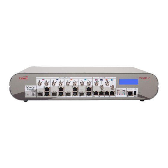
Page 5: Front Panel Description
Front Panel Description 1. P1, P3, P5, P7: unbalanced Transmitters (not enabled in this release) 2. P2, P4, P6, P8: E1 /10MHz / 2.048MHz unbalanced Receivers 3. P9, P10, P11, P12: 1pps unbalanced Receivers 4. Display 5. P14, P17, P20, P34: E1 / T1 balanced Receivers 6. - Page 6 Wander measurement. Balanced RJ48 connector. As per the copy of the Paragon-t’s Rear Panel silkscreen label above, the E1 or T1 balanced signal should be applied on the ports’ receiver (Rx) pins i.e. pins 1 and 2. Pin 3 is GND.
- Page 7 As per the copy of the Paragon-t’s Rear Panel silkscreen label above, the 1pps balanced signal should be applied on pins 3 and 6. The ToD signal should be presented on pins 7 and 8. Pin 4 is GND. 9. P29: PC Controller RJ45 This is for connection to a PC/laptop running the Windows 7, Windows Vista or Windows XP operating system.
- Page 8 23. J14: GPS Antenna Input 10. Reset Resets Paragon-t to its power-on condition and resets IP address to factory default 192.168.3.100 11. J1: DC Power Input For connection to supplied AC power adaptor only. Power supply: ac input 100 - 240V, ?.?A, 50 -...
- Page 9 Connection to balanced clock reference input signals: E1/2.048MHz (120ohm), DS1 (100ohm) and 64kb/s (110ohm). Balanced RJ48 connector. As per the copy of the Paragon-t’s Rear Panel silkscreen label above, the clock reference signal should be applied on pins 1 and 2. Pin 3 is GND.
- Page 10 120ohm, RJ48 connector. As per the copy of the Paragon-t’s Rear Panel silkscreen label above, the 1pps balanced reference signal is output on pin 3 and pin 6. The ToD signal should be output on pins 7 and 8. Pin 4 is GND.
- Page 11 At the end of life please dispose of the equipment through a recognized and approved scheme fulfilling the local environmental requirements. Alternatively contact Calnex Solutions Ltd to have them arrange for return and disposal.
- Page 12 4. Use Paragon-t’s rear panel power switch, marked 1/0, to switch on Paragon-t. 5. The blue display on the front panel turns on. The Paragon-t is initialised and ready to use when you see ‘Status: idle’ and the assigned IP address. Note that the IP address shown on the display is factory-set.
- Page 13 4. Click on Use the following IP address and enter an IP address along with associated Subnet mask and Default gateway. The IP address you enter should be different from the Paragon-t but only in the last 3 digits. (The Paragon-t 's IP address is shown on its display.) For example, if the Paragon-t shows 192.168.3.100 you could enter 192.168.3.103...
- Page 14 4. Click on Use the following IP address and enter an IP address along with associated Subnet mask and Default gateway. The IP address you enter should be different from the Paragon-t but only in the last 3 digits. (The Paragon-t 's IP address is shown on its display.) For example, if the Paragon-t shows 192.168.3.100 so you could enter 192.168.3.103...
- Page 15 For information on how to upgrade your current capability or add optional and new technology-focused capability, contact info@calnexsol.com. 4. It is possible to use the Paragon-t remote client while not connected to an instrument. In this case, use Help then Demo to enable demo mode. The GUI will then automatically use pre-configured demo capture files to simulate measurements, or the user can import and use their own capture or replay files.
- Page 16 Graphical User Interface Basics 1. WORKFLOW Use these keys in sequence (from top to bottom) to configure the Paragon-t, setup measurement ports, setup interfaces, configure capture and start/stop capture. For example, the Select Measurement Ports key, opens a window to choose the measurement port i.e.
- Page 17 4. Main Menu Use the drop down menus to select the various configurations, settings and measurement modes of the Paragon-t. Some of these duplicate workflow buttons, in which case it’s recommended to use the workflow buttons directly. 5. Mode Title Bar This identifies the tabular information that has been captured, for instance, the sample number, the sample period and the TIE.
- Page 18 From the Workflow keys: 1. Click on Start Up. 2. Enter the IP address of the Paragon-t then click on Connect to connect to the Paragon-t. Any failure to connect is likely either to be from a defective physical connection, or incorrectly set network adapter settings on the PC.
- Page 19 4. Click on Setup Interfaces. 5. Click on References, Clock Ref In to setup the reference for frequency. 6. Click on References, 1pps Ref In to set up the reference for phase.
- Page 20 7. Click on Ethernet to set up the Ethernet Line Rate, Connector and Auto-Negotiate settings. 8. Click on Clock to set up the Clock Connector for example BNC (Unbalanced) for E1 and RJ48 (Balanced) for T1.
- Page 21 9. Click on 1pps + ToD to set up the 1pps interface settings as well as the 1pps pulse threshold and, if required, the ToD RS422 interface settings. 10. Click on Configure Capture. 11. Click on Capture Period to set up capture period for each interface. The default is Manual but a fixed duration can be individually set for each interface.
- Page 22 12. Click on SyncE/ Clock (T1/E1..) to set up sample period for each interface. The default is 33.33ms but a range of other sample periods from 1ms to 10s can be individually set for each interface. 13. Click on 1pps to set up 1pps pass/fail threshold limit for each 1pps interface. The default is 1.500 us but a range of other limits from 5ns to 50us can be individually set for each 1pps interface.
- Page 23 14. Click on ToD to set up the Message Filter for ToD messages. The default is NMEA but CCSA, Cisco and NTP filters are also supported. 15. Click on Start/Stop Capture, Individual Control to start/stop measurements on a grouped or individual interface basis. Note, the user can simply use the Start All then Stop All button to start and stop measurements on all interfaces at once.
- Page 24 Frequency and then Time Interval Error (TIE). The Frequency graph i.e. E1/T1/10MHz/Sync-E Wander graph (TIE) will now be displayed: 17. Note, it is also possible to see a second graph on the Paragon-t GUI by selecting Results, Show 2nd Pane:...
- Page 25 18. To see the correct graph you need to select the ‘Results’ button on the graph you wish to change, then select the required Port i.e. Port D Frequency and then Time Interval Error (TIE). The second Frequency graph i.e. Wander graph (TIE) for the required port, in this example Port D, will now be displayed: Note: It is also possible to show additional graphs in separate windows by using the ‘Results’...
- Page 26 Accuracy graphs at the same time in one window then launch the CAT (Calnex Analysis Tool). Select ‘Results’, ‘CAT’. 21. The following window in the Paragon-t GUI will appear. Select all the ports and results you are interested in and then select ‘Export to CAT’.
- Page 27 Use the drop-down boxes on the tool as shown to select the appropriate masks. Please refer to appropriate Calnex application notes for detailed operational steps and result interpretation in relation to specific tests.
- Page 28 24. The followings shows 4 ports of 1pps Accuracy results on one tab which can each be compared against a 1pps Accuracy Threshold (i.e. Pass/Fail limit). The Pass/Fail thresholds are individually settable for each port or alternatively they can be coupled together in which case the threshold is the same for each port.
- Page 29 3. Select Start. The following screen will then appear:- 4. It is now simply a case of making the required selections on the Paragon-t GUI and the scripting commands will be recorded in the Recorded Macro screen. These can then be pasted...
- Page 30 Rb/GPS Frequency Reference The Calnex external Rb/GPS Frequency Reference can be supplied as an option to the Paragon-t (option 132), or can be ordered separately. The device provides 10 MHz and 1pps measurement references that can be used by the Paragon-t.
- Page 31 1PPS Ref Output 50 ohm BNC connector, outputs a 1pps pulse (0/5V CMOS). Pulse width 100us. RS232 This 9pin (male) connector carries the ToD (Time of Day) information. Tx ToD is pin 3, Rx ToD is pin 2 and GND is pin 5. The Baud-rate is 9600bits/sec; Data bits: 8; Stop bits: 1; Parity: none, Flow control: none, Commands: NMEA $GPRMC DC Power Input For connection to supplied AC power adaptor only.
- Page 32 At the end of life please dispose of the equipment through a recognized and approved scheme fulfilling the local environmental requirements. Alternatively contact Calnex Solutions Ltd to have them arrange for return and disposal.
- Page 33 1pps/ToD/Frequency Converter The Calnex external 1pps/ToD/Frequency converter can be supplied as an option to the Paragon-t (option 133), or can be ordered separately. Functions: Input Output Combined differential RJ-45 connector (see port 1 1pps TTL (single-ended) pulse on RJ-45 1pps+ToD serial signal pinout above).
- Page 34 Calnex Solutions Ltd www.calnexsol.com Herkimer House Mill Road Enterprise Park Linlithgow This information is subject to change without notice West Lothian EH49 7SF © Calnex Solutions Ltd, 2013 United Kingdom tel: +44 (0) 1506 671 416 May 2013 email: info@calnexsol.com...
Need help?
Do you have a question about the Paragon-t and is the answer not in the manual?
Questions and answers