Advertisement

3951 Westerre Parkway, Suite 350
Richmond, Virginia 23233 USA
MOUNTING AND WIRING INSTRUCTIONS
:
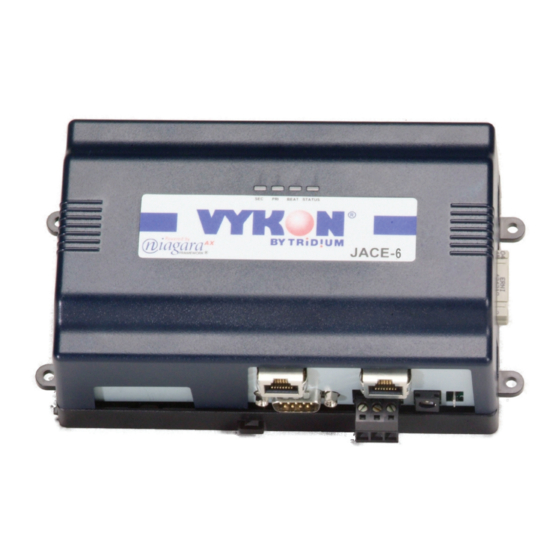
This document covers the mounting and wiring of the Vykon
series controller. It assumes that you are an engineer, technician, or service
person who is performing control system installation. Instructions in this
document apply to the following products:
Models
Description
JACE-600
JACE-6 base unit controller, powered by (either
NPB-PWR
24Vac/dc input/15Vdc output power module, DIN mountable
NPB-PWR-UN
90–263Vac universal input/15Vdc output power module, DIN mountable
WPB-XXX
Wall-mount universal AC power adapter, with different models available,
where -XXX is either: -US, -EUR, or -UK (vary by AC wall plug).
1.
In some markets, an IO-34 accessory module is available, which can power the JACE-6. See
for descriptions of accessory modules. Also see
Not covered in this document is the Niagara
Note
fully functioning unit. This includes setting host IP address and password, serial port configuration, and
other parameters. Refer to the JACE NiagaraAX Install and Startup Guide for this information.
In addition, the mounting and wiring of JACE-6 expansion options are covered in separate documents.
See sections
"About Expansion Options,"
These are the main topics included in this document:
Preparation,
page 2
Precautions,
page 3
Mounting,
page 4
Board Layout,
page 6
About Expansion Options,
Wiring Details,
page 9
Power Up and Initial Checkout,
Also included in this document are several appendixes, as follows:
Using Status LEDs,
Maintaining the JACE-6,
Replacement Parts,
Certifications,
page 22
Declaration of Conformity,
Information and specifications published here are current as of the date of publication of this document. Tridium, Inc. reserves the right to change or modify
specifications without prior notice. The latest product specifications can be found by contacting our corporate headquarters, Richmond, Virginia. Products or
features contained herein may be covered by one or more U.S. or foreign patents.
JACE-6 Mounting and Wiring Instructions
Part Number 10821
JACE-6
"Related Documentation,"
page 7, and
page 7
page 15
page 17
page 18
page 19
page 23
Published: April 19, 2007
®
JACE-6
1
):
page 16.
AX
software installation and configuration required for a
"Related Documentation,"
© 2006 Tridium, Inc.
Table 2
on page 8
page 16.
1

Advertisement

Table of Contents
loading

Summary of Contents for Tridium JACE-6 Series

  • Page 1 • Information and specifications published here are current as of the date of publication of this document. Tridium, Inc. reserves the right to change or modify specifications without prior notice. The latest product specifications can be found by contacting our corporate headquarters, Richmond, Virginia. Products or features contained herein may be covered by one or more U.S.
  • Page 2: Included In This Package

    Preparation Included in this Package Preparation Unpack the JACE-6 and power module (NPB-PWR, NPB-PWR-UN, or WPM-XXX) and inspect the package contents for damaged or missing components. If damaged, notify the appropriate carrier at once and return any damaged components for immediate repair or replacement. See “Returning a Defective Unit”...
  • Page 3: Safety Precautions

    Precautions Safety Precautions Precautions This document uses the following warning and caution conventions: Cautions remind the reader to be careful. They alert readers to situations where there is a chance Caution that the reader might perform an action that cannot be undone, might receive unexpected results, or might lose data.
  • Page 4: Environmental Requirements

    Mounting Environmental Requirements Mounting Mount the JACE-6 controller in a location that allows clearance for wiring, servicing, and module removal. Additional mounting information applies, as follows: Environmental Requirements • Physical Mounting • Environmental Requirements Note the following requirements for the JACE-6 mounting location: This product is intended for indoor use only.
  • Page 5 Mounting Physical Mounting Repeat this for all accessories, until all are mounted on the DIN rail and firmly connected to each other. Step 6 end-clips To keep the final assembly together, secure at both ends with DIN rail provided by the DIN Step 7 rail vendor.
  • Page 6: Removing And Replacing The Cover

    Board Layout Removing and Replacing the Cover Removing and Replacing the Cover You must remove the JACE-6 cover to connect the battery (new unit) or to replace the battery, and to install any option boards. The cover snaps onto the base with four plastic tabs (two on each end). To remove the cover, press in the four tabs on both ends of the unit, and lift the cover off.
  • Page 7: About Expansion Options

    About Expansion Options About Option Cards About Expansion Options The JACE-6 provides for field-installable expansion with two kinds of options: Option cards—Install on connectors inside the JACE-6 base unit. See “About Option Cards”. • Accessory modules—To “chain” onto the JACE-6’s 20-pin connector. See “About Accessory Modules”.
  • Page 8: About Accessory Modules

    About Expansion Options About Accessory Modules Procedure 2 Mounting option cards on a JACE-6. Remove power from the JACE-6—see the previous Warning. Step 1 Remove the cover. See “Removing and Replacing the Cover,” page 6. Step 2 Remove the battery and bracket assembly by taking out the four screws holding it in place, setting the Step 3 screws aside for later.
  • Page 9: Wiring Details

    Wiring Details Grounding Table 2 JACE-6 accessory modules. (continued) Model Description Notes IO-16 DIN-mountable, 16 points I/O module, Provides the following I/O points: used to provide I/O points as noted. • 8 - Universal Inputs (UIs). • 4 - Digital Outputs (DOs), SPST-relay type. •...
  • Page 10: Power Wiring

    Wiring Details Power Wiring Power Wiring The JACE-6 must be powered by an approved 15 Vdc power source. This can be either an external wall mount AC adapter (WPM-XXX), a DIN-mount 24Vac/dc-powered module (NPB-PWR), or a DIN-mount line line-powered (90–263 Vac) module (NPB-PWR-UN). The JACE-6 controller does not include an on/off switch.
  • Page 11 Wiring Details Power Wiring If powering from a 24V transformer, do not power any other equipment with it. Otherwise, conducted Note noise problems may result. Also, do not ground either side of the transformer’s 24V secondary. Figure 3 NPB-PWR module wiring connections. NPB-PWR (cover shown removed) JACE-6 Earth Ground...
  • Page 12: Communications Wiring

    Remove cover 6-pin connector not used NOTE: The 6-pin connector of the NPB-PWR-UN is not used with a JACE-6 series controller. JACE-6 or last IO-16 The 6-pin connector is designed for use with the Security JACE (SEC-J-201) and associated security...
  • Page 13 Wiring Details Communications Wiring Prior to connecting cables, provide strain relief for them to prevent damage to the controller. Note Figure 5 JACE-6 bottom side (cover removed). Ethernet (RJ-45) Primary Ethernet (RJ-45) LAN 2 LAN 1 Battery in bracket (on top of option port cards, if any) (future use)
  • Page 14 Wiring Details Communications Wiring If a modem option card (NPB-MDM) is installed, this port becomes disabled—except if rebooted with Note the mode jumper (see Figure 2 on page 6) in the “Serial Shell” position. Table 3 Serial port (RS-232 and RS-485) pinouts. Base RS-232 DB-9 Port (COM1) Base RS-485 Port (COM2) Pinout References...
  • Page 15: Power Up And Initial Checkout

    Power Up and Initial Checkout Connect the Backup Battery Power Up and Initial Checkout Ensure power wiring to the JACE-6 is ready—see the “Power Wiring” section on page 10. Refer to Figure 2 page 6 for the locations of the JACE-6 battery connector, status LEDs and barrel power connector (for WPM-XXX only).
  • Page 16: Check The Status Leds

    Related Documentation Check the Status LEDs Check the Status LEDs When power is applied, the green LED labeled “STATUS” will light. This indicates that the system is OK and that power is applied. Once the JACE-6 boots, the yellow “BEAT” (heartbeat) LED will begin blinking, with a typical rate of about 1 Hz.
  • Page 17: Using Status Leds

    Using Status LEDs Ethernet Ports Using Status LEDs The JACE-6 controller includes several LEDs that can help determine the status of the unit. They are located in two places: the top of the controller (visible through the cover), and for serial ports, on the bottom board (only with cover removed).
  • Page 18: Required Battery Maintenance

    Maintaining the JACE-6 Cleaning Maintaining the JACE-6 This section provides information on the following topics: Cleaning • Required Battery Maintenance • Replacement Parts • Replacing the JACE-6 base assembly • Returning a Defective Unit • Cleaning If dust or metal filings are present inside the unit, clean with vacuum or compressed air. Otherwise, no cleaning inside the unit is required.
  • Page 19: Non-Replaceable Parts

    The JACE-6 contains a non-user replaceable fuse, soldered on the circuit board. This fuse provides protection from internal shorts or connection to incorrect power supplies. If the fuse circuitry is suspect, contact your regional Tridium office for technical support. See the “Returning a Defective Unit”...
  • Page 20: New Replacement Units

    “field replacement units,” or FRUs, with separate part numbers. If the faulty JACE-6 is still in warranty, you can receive credit by returning it to Tridium. Be sure to contact Tridium for a return authorization (RA) number before shipping an item for return credit. See “Returning a...
  • Page 21: Returning A Defective Unit

    For proper credit on an in-warranty unit, ship the defective unit to Tridium within 30 days. Prior to returning the unit, contact one of the following Tridium offices to obtain a return authorization (RA) number and other instructions. Please provide: •...
  • Page 22: Federal Communications Commission (Fcc)

    +65 6887 5342 Phone: Fax: +65 9665 6024 Mobile: Address: Email for technical support: Tridium Asia Pacific Pte Ltd 101 Cecil Street, hclim@tridium.com #10-11, Tong Eng Building, Singapore 069533 Attn: Mr Lim Hoon Chiat, Engineering Manager RA# ____________ (Australia): +61 7 5539 1211...
  • Page 23: Declaration Of Conformity

    I, Terry Casey, hereby declare that the equipment specified above conforms to the above Directives and Standards. Place: Coolham, West Sussex, United Kingdom December 1, 2006 Position: President, Tridium Europe Ltd. JACE-6 Mounting and Wiring Instructions Part Number 10821 Published: April 19, 2007...
  • Page 24: Tab Mounting Dimensions

    Tab Mounting Dimensions 0.170” Dia. 6.719” (170.66mm) (4.32mm) JACE-6 3.75” (95.25mm) Note: Electronic and printed versions of this 2.50” guide may not show the dimensions to scale. 4.00” (63.50mm) (101.6mm) Verify all measurements before drilling. DIN mounting is recommended over tab mounting. Figure 1 on page 5.

This manual is also suitable for:

Jace-600

Table of Contents