Table of Contents
Advertisement
Installation and Operating Instructions
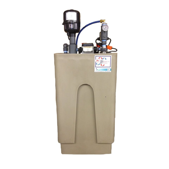
The Bubble‐Up® Interactive unit from R.E. Prescott Co., Inc. is designed to remove radon gas from water. Radon is a radioactive gas
which can cause serious health problems. Inside the unit, air is blown into the incoming water and allowed to bubble upward. This
bubbling action releases the radon from the water. Air containing the radon is then collected and vented out.
Bubble‐Up® Jr Interactive™
U.S. Patent # 6,372,024 and 8,393,875
Installation and Service By:
Rev. January 2019
Advertisement
Table of Contents

Subscribe to Our Youtube Channel
Summary of Contents for R.E Prescott Bubble-Up Jr Interactive
- Page 1 Rev. January 2019 Bubble‐Up® Jr Interactive™ Installation and Operating Instructions U.S. Patent # 6,372,024 and 8,393,875 ...
-
Page 2: Table Of Contents
Bubble‐Up® Jr Interactive™ Radon Removal System Table of Contents Specifications 3 Inlet and Outlet Flow and Pressure Specifications 4 Controls and Indicators 7 Installation 8 Start‐Up Procedure 12 Operating Instructions 12 Maintenance 13 Trouble Shooting 14 Replacement Parts Listing 20 Start‐Up Data 23 Start‐Up Notes 24 Appendix A‐ 7 gpm Mechanical Head Manual 25 B‐ Meter Control Manual 28 C‐ Bubble‐Up Warranty 30 ... -
Page 3: Specifications
Bubble‐Up® Jr Interactive™ Radon Removal System Specifications Dimensions: Depth: 18” Width: 24” Tank Height: 41” Overall Height: 60” Maximum water depth: 26” (off float switch level) Refill water depth: 19” (on float switch level) Run dry water depth: 5” Cycle Tank: 2.1 Gallon, 3/4” MNPT, 8” Diameter X 10” Tall, Water Expansion Tank Water Capacity: On/Off Cycle Volume: 7 Gallons Usable water at maximum water depth of 26”: 34 Gallons Usable water at refill water depth of 19”: 27 Gallons Approximate Weight: 90 lb. empty 373 lb. filled to maximum water depth of 26” 507 lb. filled to overflow water depth of 41” Influent Water Requirements: Hardness < 68 mg/l (4 GPG) Iron < 0.03 mg/l Manganese <0.05 mg/l Plumbing Connections: 1” male npt water inlet and outlet bypass valve 2” FNPT air inlet with nipple for directly mounting Bubble‐Up® Jr Interactive™ blower 2” Fernco air outlet 1.25” fnpt overflow connection 3/4" Male npt for expansion tank ... -
Page 4: Inlet And Outlet Flow And Pressure Specifications
Bubble‐Up® Jr Interactive™ Radon Removal System Pump controller: Bubble‐Up Mechanical Pump Control with a low water float switch, 7 GPM Standard or 14 GPM Adder, protects the pump from running dry, integral check valve, and operates the pump from a 2.1 gallon tank, 115V AC Radon Removal Efficiency: MODEL GPM EFFICIENCY Bubble‐Up® Jr Interactive™ 7 99% 7 GPM Standard, 1/2” Solenoid Bubble‐Up® Jr Interactive™ 14 98% 14 GPM Adder, 3/4" Solenoid Inlet Flow and Pressure Specifications ... - Page 5 Bubble‐Up® Jr Interactive™ Radon Removal System Outlet Flow and Pressure Specifications 7 GPM Mechanical Pump Control Pressure vs. Flow House Pressure Control Pressure Flow (GPM) Figure 2 ‐ Bubble‐Up® Jr Interactive™ Outlet Flow vs. Pressure 7 GPM 14 GPM Mechanical Pump Control Pressure vs. Flow House Pressure Control Pressure 14 GPM Pump Control w/ 3/4” Pex Flow (GPM) Figure 3 – Bubble‐Up® Jr Interactive™ Outlet Flow vs. Pressure 14 GPM 5 ...
- Page 6 Bubble‐Up® Jr Interactive™ Radon Removal System Tested Results Radon Removal vs. Flow Flow (GPM) Figure 4 – Radon Removal vs. Flow 99% Removal at 7 GPM 6 ...
-
Page 7: Controls And Indicators
Bubble‐Up® Jr Interactive™ Radon Removal System Controls and Indicators Bypass valve This valve can be used to divert the water flow if a problem develops with the Bubble‐Up® Jr Interactive™ unit. This valve has two red handles, and is located near the back of the unit. See Figure 7. The valve has two positions: • Service ‐ This is the normal operating position. When the two valve handles are in line with water flow, the unit can remove radon from the incoming water. • Bypass ‐ When the two valve handles are perpendicular to water flow, the incoming water “bypasses” the Bubble‐Up® Jr Interactive™ unit. Use this position only if there is a problem with the unit. Caution! When the bypass valves are set to the Bypass position, the Bubble‐Up® Jr Interactive™ unit cannot provide any protection against radon in the water. Meter Control For instructions regarding the meter control refer to the Bubble‐Up Meter Control manual in the appendix and online at www.represcott.com Mechanical Pump Control For instructions regarding the mechanical pump control refer to the Bubble‐Up Mechanical Pump Control Assembly Owner’s Manual in the appendix and online at www.represcott.com. Water Alarm Valve The water alarm valve control is designed to identify leaking problems in the Bubble‐Up® Jr Interactive™. It is designed to monitor radon vent obstruction, high water and fitting leaks. It does this by incorporating a water alarm valve float switch, water alarm floor sensor and water alarm tank top terminal block sensor to signal the water alarm valve control which operates the motorized water alarm ball valve. See figures 13 and 14. Important Feature: The water alarm valve can also be used to create any number of remote leak detection points by connecting extra leads to the leads of the terminal block. Users Guide: Please choose the correct mode on the mode switch shown in the picture according to the application. In the case of the Bubble‐Up® Jr Interactive™, the switch should be in the normal water position. See figure 5* The buzzer will beep if there is a radon vent pipe obstruction, high water alarm or detected water leak, and at the same time a signal will be sent to the external motorized ball valve. This signal will cause the ball valve to ... -
Page 8: Installation
Bubble‐Up® Jr Interactive™ Radon Removal System Figure 5 – Water Alarm Valve Installation 1. Be sure the float switches are not tangled around the pump by removing the 2” vent fitting and visually inspecting the float. 2. The Bubble‐Up® Jr Interactive™ comes with a standard 2.1 gallon water expansion tank. Plumb this expansion tank near the outlet of the Bubble‐Up® Jr Interactive™. Note: This expansion tank can be used for a certain amount of water heater thermal expansion. If you have a tank type water heater, check manufacturer’s requirements for sizing thermal expansion tank. Radon Testing Note: It is important to install a new sample valve or boiler drain in new piping so that the radon testing is not influenced by old piping. 3. Set the main tank of the Bubble‐Up® Jr Interactive™ in the desired location that can hold the weight of the Bubble‐Up® Jr Interactive™ shown in the Specification Section on page 2. Choose a flat, level surface with ample set‐up space. 4. In case of a malfunction, the unit could overflow. The Bubble‐Up® Jr Interactive™ is fitted with an overflow pipe. (The overflow pipe is mounted near the rear of the unit. See Figure 7) Take this into account when positioning the unit. It is best if the unit can be positioned near a drain or sump pit with a sump pump. ... - Page 9 Bubble‐Up® Jr Interactive™ Radon Removal System stress on the plumbing and cause leaks. In this kind of situation, a pressure regulator should be installed on the outlet side of the unit and drawdown tank. 7. The Bubble‐Up® Jr Interactive™ requires a quadplex outlet wired to a dedicated 20A circuit. Use a 20 amp duplex GFCI receptacle for the yellow float switch cord for UL (See Figure 8). This circuit should use #12 AWG wiring. 8. Install the 2.1 gallon water expansion tank on the outlet side of the unit. See Figure 11. This tank is included to prevent the pump from starting and stopping quickly (“short cycling”) when there are short‐term demands for small amounts of water. 9. Install a pre‐filter on the inlet side to protect the solenoid from sediment clogging. See figure 11. The pre‐filter should be a sediment‐type filter with a 5 micron rating. Do not use a carbon‐type filter. 10. Attach the red handled bypass valve. 11. The bypass valve is included so that the unit can be taken out of service easily without interrupting the water supply. Plumb the inlet line and outlet line so that the water can continue the water demand if the bypass valve is set to the bypass position. 12. Pour one ounce of bleach into the blower attachment nipple to disinfect the unit. See Figure 6 for location of blower attachment nipple. 13. Firmly slip the blower onto the blower attachment nipple and tighten clamp to secure blower to nipple. Caution! Do not use PVC pipe cement on this connection. Note: If blower inlet is connected to draw air from an outdoor source, make sure that no moisture can get into a blower motor. If an outdoor source is desired, a dryer vent kit can be modified by removing the flap check and replacing it with a screen. Be sure to install the kit as directed and run the hose down to the floor in the area of the Bubble‐Up® Jr. Interactive. 14. Plug in the following cords. Refer to figures 6, 7, & 8. • Plug blower cord into duplex outlet. • Plug solenoid cord into duplex outlet. • Plug fill piggy‐back float switch cord into yellow float switch cord •...
- Page 10 Bubble‐Up® Jr Interactive™ Radon Removal System Important information about venting: Since the Bubble‐Up® Jr Interactive™ unit removes radon in the water; the unit must be vented carefully. Common practice is to run the vent up past the roof line of the building. An elevated vent opening provides the best way of dissipating the radon gas. Protocols recommend extending the vent opening 2’ above the highest opening in the building, and at least 10’ away from the nearest opening. It is recommended to protect the vent opening with a vent screen. A single free hard (printed) copy of the ASTM E‐2121 standard (Recommended Residential Radon Mitigation Standard of Practice) is available from EPA’s National Service Center for Environmental Publications (NSCEP). You can order a copy by phone at 1‐800‐490‐9198, via E‐mail nscep@bps‐lmit.com, or via the internet at www.epa.gov/nscep/ordering.htm Please use the EPA document number (402‐K‐03‐007) when ordering E‐ 2121. EPA reprints E‐2121 under agreement with ASTM International. 17. Plumb the mechanical pump control and plug pump cord into low water piggy‐back float cord. Plug the low water piggy‐back float cord into the female cord of pump control. See Figure 7. 18. Check all plumbing fittings to be sure all fittings are water tight. 19. The water alarm valve control is wired to the power supply, motorized ball valve, and water sensor terminal block. 20. Install 9V battery backup into water alarm control. 21. Terminal block wires are connected to high water alarm valve control, water alarm float switch and water alarm floor sensor. These wires are twisted together and connected to terminal block. Note: Water Sensor Terminal Block Connection: Connect the water alarm float wire, water alarm control (figure 6), and water alarm sensor wires to the terminal block (The terminal block is located next to the air vent, figure 7). Connect one wire to the black connection of the terminal block and the other wire to the red connection of the terminal block. It is very important that this is a good connection. Bubble‐Up Blower Mechanical Pump Control 2” Blower Attachment Plug Blower and Solenoid ...
- Page 11 Bubble‐Up® Jr Interactive™ Radon Removal System Mechanical Pump Control Standard 54/65 Pressure Switch Water Inlet and Outlet (Bypass Valve) Overflow Pipe Remove 1 1/4” Plug Water Sensor Terminal block Figure 8 ‐ Power Cords Black Pump Control Cord Water Alarm Valve ...
-
Page 12: Start-Up Procedure
Bubble‐Up® Jr Interactive™ Radon Removal System Start Up Procedure 1. Set the red handles on the bypass valve to the Service position. 2. Before plugging in Bubble‐Up® Jr Interactive™, identify the plug‐in cords. See figure 8. 3. Plug in the meter control and water alarm valve control power cords. 4. Push reset button on water alarm valve control for 3 seconds to open the motorized ball valve. 5. Plug in the yellow cord first. The blower should start, and the solenoid valve should open to begin filling the tank. 6. As the water level in the tank rises, the fill float switch will tilt up. This will stop the blower and close the solenoid valve. 7. Once the tank is full, plug in the black pump control cord. 8. If the pump does not start delivering water to the house, it may be necessary to prime the pump. (Normally you will only have to do this once, when the unit is first installed.) The pump is suspended by a pipe underneath the pump control. Unscrew the union and move the pump control off to the side. You may need to siphon or vacuum the water up this pipe to remove the air from the pump and prime it. 9. Once the air has been removed from the pump, replace the pump control and tighten the union. Plug in the pump. If the pump does not start delivering water to the house, repeat the priming sequence. 10. After the unit is operating, run a radon test of the raw water and the filtered water to ensure that the unit is reducing radon levels in the water. Radon Testing Note: It is important to install a new sample valve or boiler drain in new piping so that the radon testing is not influenced by old piping. 11. Perform the six‐month maintenance procedure, and fill out the Start‐Up Data page at the end of this manual. Operating Instructions Once the Bubble‐Up® Jr Interactive™ has been installed, it should operate with very little attention. ... -
Page 13: Maintenance
Bubble‐Up® Jr Interactive™ Radon Removal System Bypassing the Unit If a problem develops, the Bubble‐Up® Jr Interactive™ unit can be taken out of the water supply system with the bypass valve. The rest of the water system will operate normally, but the Bubble‐Up® Jr Interactive™ will not be able to provide any protection against radon in the water. Caution! Do not continue to operate the water supply system this way for a long time. Correct the problem with the Bubble‐Up® Jr Interactive™ and return it to service as quickly as possible. Maintenance Every six months: • Check the operation of the float, pump control, solenoid valve, and the blower by turning on a water tap and allowing it to run. At first, the water will be supplied by the 2.1 gallon water expansion tank, and then the pump should turn on. A few minutes later, you should hear the blower start and the solenoid valve should open. (The unit cannot remove radon unless the blower is working.) • Check the incoming flow rate on the meter control. Typical well pump fill rates are between 4 and 7 GPM. Higher flow rate systems are available. • Shut off the water tap. The tank in the Bubble‐Up® Jr Interactive™ unit should fill in less than two minutes. • Check the outlet of the vent line to ensure that it is not blocked. • Check that the motorized ball valve is operating correctly by crossing the leads of the terminal block or raising the high water float, or wetting the floor sensor. This should activate the motorized ball valve and shut off all incoming water. Hold the RESET button on the front of the water alarm valve control for three seconds to return the motorized ball valve to its open position after each test. • Disinfect the unit as needed. (Pour one ounce of bleach into the blower attachment nipple.) • Replace 9‐volt battery in Water Alarm Valve Control Every year: We recommend that you have your Bubble‐Up® Jr Interactive™ unit checked once a year by a qualified installer. The yearly checkup may include these steps: • Run raw water and filtered water radon tests. • Replace the cartridge in the pre‐filter and disinfect. •... -
Page 14: Trouble Shooting
Bubble‐Up® Jr Interactive™ Radon Removal System 8. Remove the manifold by disconnecting it from the bypass valve and removing the mounting screw located behind the meter control. 9. Undo the 8 screws around the large circular top cover. Carefully remove the cover, with the attached internal tank. Now you can clean the inside of the tank. 10. Pump or siphon the water out of the tank. 11. Vacuum out any remaining water with a wet/dry vacuum. 12. Wash down the inside of the tank. This may require some scrubbing. If a layer of minerals has collected at the bottom of the tank, remove this layer. If the mineral layer includes a rusty material, you may have to use a reducing chemical to dissolve and neutralize the rust. 13. As a final step, sanitize the inside of the tank using a dilute solution of chlorine bleach. Rinse, then vacuum out any remaining water. 14. Re‐install the circular top cover with the internal tank and air‐water coupling. Check the gasket to make sure it is properly sealed. Replace the gasket if necessary. 15. Reconnect the water supply line to the air‐water coupling below the blower. 16. Disinfect the unit. (Pour one ounce of bleach into the blower attachment nipple.) 17. Install the blower. Firmly slip the blower onto the blower attachment nipple and tighten clamp. 18. Set the bypass valve to the Service position 19. Restart the unit. Follow the instructions in the “Start up Procedure.” 20. Check all seals to ensure they are air or water tight. Removing the Pump and Low Water Float: 1. Unplug both power cords to the unit. Set the bypass valve to the Bypass position. 2. Remove piping on top of mechanical pump control and unscrew 1” union located under the mechanical pump control. ... - Page 15 Bubble‐Up® Jr Interactive™ Radon Removal System This situation can be caused by simply using more water out of the Bubble‐Up® Jr than what is coming in. Compare water outlet flow with “current flow” meter control reading on the Bubble‐Up® Jr while filling. A few inlet flow problems are; low yield well, well pump failure, clogged plumbing or water filtration restricting water flow filling the Bubble‐Up® Jr. No water from the Bubble Up (alarm is sounding) Cause: Water Alarm Valve shut water off to Bubble‐Up® Jr. Example: The Bubble‐Up® Jr Interactive includes a water alarm valve which sounds an alarm and stops water filling the Bubble Up when a leak or overflow condition is detected. Once water stops filling the Bubble‐Up® Jr, continued water use will cause the low water float switch to stop the Bubble Up pump from delivering water flow to the house. Examples: The alarm conditions to cause the water alarm valve to close and stop water from entering the Bubble‐Up® Jr are; 1‐ the water sensor box detects water on the floor around the Bubble‐Up® Jr 2‐ the water sensor terminal block detects water on top of the Bubble‐Up® Jr or 3‐ the high water float switch senses high water in the main tank. These conditions are caused by water detection due to high water levels, water leaks, condensation Etc. Also if the air vent piping is restricted the Bubble‐Up® Jr blower cannot freely blow the air out of the Bubble‐Up® Jr. This will cause blower back pressure which will force water up the overflow pipe to be released through the breather vent, causing the sensors on the terminal block to detect an overflow of water. Vent piping back pressure can be caused by an obstruction, ice build‐up, water trapped in a reverse pitch, excess pipe fittings or pipe length. High‐Water Alarm A few things can cause the high‐water alarm valve control to sound: The leak detection terminal block or floor sensor is wet, repair leak and dry off the top of the Bubble‐Up® Jr Interactive™. ...
- Page 16 Bubble‐Up® Jr Interactive™ Radon Removal System Bubble‐Up Mechanical Pump Bubble‐Up Blower Control BUB075A BUB008 Blower Attachment Nipple BUB022 Figure 9 16 ...
- Page 17 Bubble‐Up® Jr Interactive™ Radon Removal System Bubble‐Up Mechanical Pump Control ‐ BUB075A PVC Union – BUB024 Well Seal – BUB012 Fill Float Switch Assembly BUB007 Pump Assembly, Including Motor, Impellor, and Check Valve – BUB051B Figure 10 ‐ Pump Assembly with Control Pre‐filter, Paper Element – 83310 (Sold separately) 2.1 Gallon Water Expansion Tank – Figure 11 – Accessories 41510 (included with purchase) 17 ...
- Page 18 Bubble‐Up® Jr Interactive™ Radon Removal System Figure 12 – Bubble‐Up Mechanical Pump Control – BUB075A Retrofit Kit A retrofit kit is available to convert an XP style Bubble‐Up to a Bubble‐Up Interactive. This kit includes all of the parts necessary for the conversion. Seen below are the parts included in the retrofit kit. Figure 13 – Interactive Components Water Alarm Valve Control Auxiliary Water Alarm Sensor 9 volt Battery Water Alarm Power Supply Water Alarm Bracket Terminal Block and Screws Motorized Ball Valve and Solenoid Assembly (1/2” or 3/4”) 18 ...
- Page 19 Bubble‐Up® Jr Interactive™ Radon Removal System Water Alarm Float Wires Connect to terminal Block Bubble‐Up® Jr Interactive™ Overflow Pipe with Plug and Vented Elbow Low water float switch grommet High Water Alarm Float Assembly ...
-
Page 20: Replacement Parts Listing
Bubble‐Up® Jr Interactive™ Radon Removal System Parts Listing: Item# Description Quantity Unit BUB057 Bubble‐Up Jr Interactive Tank 1 each Bubble‐Up Jr Interactive Tank BUB058 1 each Cover BUB009 PVC Manifold – air‐water coupling 1 each BUB004 9" Grid chamber with grids 1 each BUB011 6' supply cord 16/3, yellow 1 each BUB007 Solenoid Float switch assembly 1 each BUB008 Blower 1 each BUB012A 5" X 1" Gasket #3231 1 each BUB012B ... - Page 21 Bubble‐Up® Jr Interactive™ Radon Removal System BUB036 2" Adaptaflex, Air Outlet 1 each BUB037 1.25" Adaptaflex, Overflow 1 each BUB038 5/8" Delrin Sleeve 2 each 5/8" X 1/2" W/Stop Ell – Nickel BUB042 1 each Plated BUB044 Pump Cord Plug 1 each BUB045 1/2" SS Pex Insert 2 each BUB046 1/2" X 20' Pex Tubing 0.1 each BUB048 2" S.S. Clamp 1 each Sta‐Rite Bottom Suction, BUB051B 1 each 20DOM05121+1 7 GPM Mech. Pump Control BUB075C ...
- Page 22 Bubble‐Up® Jr Interactive™ Radon Removal System Water Alarm Control Bracket BUB055D 1 each Mount Water Alarm Control Bracket BUB055E 2 each Screw BUB055F Water Alarm Control Bracket Nut 2 each PA‐260‐300 Leak Sensor Terminal Block 1 each Leak Sensor Terminal Block BUB055G 2 each Standoff (1/4" nylon) BUB055H Leak Sensor Terminal Block Screw 2 each BUB009B 1/2" XP Adapter 1 each CV3151 AB1 Nut 1 each CV3150 Split Ring 1 each 2" SCD 80 PVC Street X Female Air ...
-
Page 23: Start-Up Data
Bubble‐Up® Jr Interactive™ Radon Removal System Start‐Up Data For service, call: ______________________________________________ Installer: ______________________________________________ Address: _____________________________________________________________________________ _____________________________________________________________ Serial Number: __________________________________________ 23 ... -
Page 24: Start-Up Notes
Bubble‐Up® Jr Interactive™ Radon Removal System Start‐Up Notes Fill Rate: ______________________________________________ Radon In: ______________________________________________ Radon Out: ______________________________________________ 24 ... -
Page 25: Gpm Mechanical Head Manual
Bubble‐Up® Jr Interactive™ Radon Removal System Appendix: A 7 GPM Bubble‐Up Mechanical Pump Control Assembly Manual Part Number BUB‐075A, 7GPM Standard 45/65 Pressure Switch For use with only 115 volt Bubble‐Up pumps. Patent Number: US 8,393,875 B2 SETTING PRESSURE SWITCH FOR PROPER OPERATION: 1. Always unplug the pressure switch before removing pressure switch cover and making adjustments. See pressure adjustment instructions under the cover. 2. Adjust the large spring only until the pressure switch turns on at 45 PSI. 3. Do not adjust the small spring. This will keep 20 psi differential. HOW IT WORKS Pressure switch is connected to the venturi throat pressure. When there is ½ to 1 GPM flow through the venturi the pressure switch senses less than 65 psi. This keeps the pump running at low flows. 25 ... - Page 26 Bubble‐Up® Jr Interactive™ Radon Removal System C. INSTALLATION 1. Use only 115 volt outlet for the Bubble‐Up mechanical pump control. 2. The bottom 1” schedule 80 union and top ½” PEX fittings are to be water tight and secure. 3. Check that the pump is primed before plugging in the Bubble‐Up mechanical pump control. 4. The Bubble‐Up mechanical pump control is supplied with 115 volt electrical cords. Connect the pump’s male power plug into the Bubble‐Up mechanical pump control female cord. 5. To start the pump, refer to OPERATION below. 6. The pressure switch factory set at to turn the pump on at 45 PSI. To set pressure switch for proper operation see instructions above. WARNING! Unplug the Bubble‐Up mechanical pump control before removing the pressure switch cover. 7. Always use the bladder tank provided with the Bubble Up. The correct pre‐charge air pressure in the tank is 40 psi. D. OPERATION See setting pressure switch above. The Bubble‐Up mechanical pump control starts the pump when the pressure drops to 45 PSI. The pump will run constant when the flow is greater than ½ to 1 GPM. When water flow falls below ½ to 1 GPM, water fills the required cycle tank providing a minimum run time before the pump is shut off. Internal parts include: 2 ‐ Check Valves, a Nozzle and Throat Assembly with retainer, Double Check Valve and Nozzle Retainer and 3 screws. ...
- Page 27 Bubble‐Up® Jr Interactive™ Radon Removal System 7 GPM Mechanical Pump Control Parts List 1. 5/8" X 3/4" W/ Stop ELL‐NP 9. Stainless steel nozzle retainer (single) 2. 1 1/4" X 3/4" Bushing‐NP 10. Nozzle and Throat (part of repair kit) 3. 1 1/4" Bubble‐Up Mechanical Pump Control Body 11. Stainless steel screws (qty. 3) 4. Back Mount Pressure Gauge 12. 1/4" PVC plug 5. 45/65 Standard Pressure Switch 13. Male And Female 115 Volt Power Cords 6. 1/4” Nickel plated hex nipple 14. Power cord connects to pressure switch (qty. 2) 7. Check valve (qty. 2, part of repair kit) 15. 1" Male X 1 1/4" Male Check Valve 8. Stainless steel check retainer (Single) 16. 1" PVC SCD 80 Union 7 GPM Mechanical Pump Control Pressure vs. Flow House ...
-
Page 28: B- Meter Control Manual
Bubble‐Up® Jr Interactive™ Radon Removal System Appendix: B Meter Control Manual Meter Control for Bubble Up XP and Interactive™ ® Part Number BUB080 Ver. 101.1 Display Operation The display on the meter control system displays the following information by pressing the corresponding buttons. These are (working from left to right across the display): Flow: Displays CURRENT flow rate, gal/min. Total Flow: Displays TOTAL gallons treated since last meter reset, gal. Peak Flow: Displays PEAK flow rate since last meter reset, gal/min. The display also has three informative lights: Green Power Light: System is plugged in and fully functioning. Yellow Warning Light: Will blink when system is at 80% of threshold gallons. Red Expired Light: Lit when system is at 90% of threshold gallons. ... - Page 29 Bubble‐Up® Jr Interactive™ Radon Removal System At 100% threshold gallons the red light will blink, and the meter control will beep three times every 15 seconds and output 2 will provide 12 V AC 30 ma power. The beep can be silenced by pushing any button, and will remain silent for two days. To reset threshold and or beep continue to programming. Programming Press all three buttons of the display simultaneously to enter Program Mode: The Flow button toggles to next screen, also acts as the Enter Button. The Total Flow button toggles the values up. The Peak Flow button toggles the values down. Screen One: CLR MEMORY YES NO. YES to clear memory and reset threshold or NO to continue programming. Next Screen: SET PULSES Should be factory set at 83 pulses. Next Screen: SET THRESHOLD TOTAL YES or NO Choose YES or NO to use threshold function. The threshold function utilizes the yellow and red display lights, along with 12 V AC Output 2 and audible alarm. Next Screen: SET THRESHOLD TOTAL (set gallons for 12 V AC at connection Opt2, .030 amps max.) Should be factory set at 80 which translates to 80,000 gallons. 80,000 gallons is an estimated yearly service reminder for 4 people using 50 gallons per day each. This threshold can be set for your particular application at this time. Yellow Warning Light will flash at 80% of threshold gallon setting. Red Expired Light will light at 90% of threshold gallon setting. ...
-
Page 30: C- Bubble-Up Warranty
Bubble‐Up® Jr Interactive™ Radon Removal System Appendix: C Bubble Up® Warranty April 1, 2010 R.E. Prescott Co., Inc. warrants to the original purchaser of the Bubble Up® radon system that the product is in good working condition, according to its specifications at the time of shipment, for a period of three years from the date of original purchase. Should the product, in R.E. Prescott Co., Inc.'s opinion, malfunction within the warranty period, R.E. Prescott Co., Inc. will at its discretion repair or replace the Bubble Up upon receipt with an equivalent unit. Any replaced parts become the property of R.E. Prescott Co., Inc. This warranty does not apply to a Bubble Up which has been damaged due to accident, misuse, abuse, improper installation, usage not in accordance with product specifications and instructions, natural or personal disaster, or unauthorized alterations, repairs or modifications. The warranty applies only to defects in workmanship. The warranty makes no claims regarding suitability of the product for a particular use or environment. Only products manufactured by R.E. Prescott Co., Inc. are covered by the standard warranty. Third party products used in R.E. Prescott Co., Inc. components will be covered by the third party warranty. A serial number is required for any warranty service. R.E. Prescott Co., Inc. asks you to record the serial number on the outside of the packaging when shipping the product. Proof of purchase may be required, but only if some doubt exists regarding warranty eligibility. Late model products are assumed to be under warranty. R.E. Prescott Co., Inc. accepts originals, photocopies and faxes as proof of purchase when required. Unauthorized repairs to an R.E. Prescott Co., Inc. product will void the warranty offered by R.E. Prescott Co. R.E. Prescott Co., Inc. reserves the right to refuse to service any product which has been altered, modified or repaired by non‐R.E. Prescott Co., Inc. authorized service personnel. After a warranty has expired, R.E. Prescott Co., Inc. charges a flat rate of $75.00 per hour to repair the product. Other circumstances which violate the terms and conditions of the warranty (abuse, misuse, unauthorized repair, etc.) are not eligible for this "out of warranty" arrangement. ...
Need help?
Do you have a question about the Bubble-Up Jr Interactive and is the answer not in the manual?
Questions and answers