Table of Contents
Advertisement
Module Air Processing Systems (MAPS III) Manual for Option D21 Makeup Air Control
1.0 Digital Controller ............................................ 1
1.1 Display Function Keys ...................................1
1.2 Thermostat Display .......................................2
2.0 Sequence of Operation ................................. 5
2.1 States of Operation .......................................5
2.2 Modes of Operation .......................................6
3.0 Controls .......................................................... 6
3.1 Supply Fan Control........................................6
3.2 Intake Damper Control ..................................8
3.3 Temperature And Humidity Control ............... 9
3.4 Heating Control ...........................................10
3.5 Cooling Control............................................10
3.6 Dehumidification ......................................... 11
12
4.0 Safeties and Alarms .................................... 13
4.1 Alarms .........................................................13
4.2 Alarm Management .....................................16
1.0 Digital
Controller
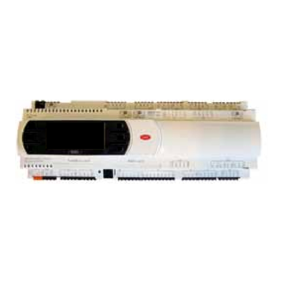
The control system utilizes a factory installed remote display which allows for complete access to unit test features, schedules,
discharge air setpoints, fan control, alarms, and other unit operational setpoints. The control features include:
•
Local and remote alarming
•
Integrated time clock
•
Compressor anti-cycle protection and minimum "on/off"
cycle rates
•
Multiple protocol support [BACnet
1.1 Display Function
Keys
Example of Remote Controller Display (Option RB5 or RB6) Key Symbols
Function Key Identification
Function Key Display on the
Remote Controller
®
Applies to: Models RCB, RDB, RECB, REDB, RDCB, RDDB
Table of Contents
(MSTP) or LonWorks
®
Alarm
5.0 Start Up ......................................................... 19
5.1 Set the Date, Time on the controller Clock & unit time
schedule ......................................................19
5.3 Unit Test Mode ............................................20
6.0 Controller History Log ................................. 24
7.0 Controller Display Menus ........................... 25
8.0 Communication Cards ................................ 34
®
34
®
Index ................................................................... 42
•
Alarm shutdown feature
•
Commissioning and test mode functions
•
Optional wall mounted or handheld remote display
•
Energy conscious applications
•
]
®
TAB menu for creating a backup of setpoints
Prg
Esc
Form CP-MAPSIII-D21 (09-15)
Up
Enter
Form CP-MAPSIII-D21, Doc No 303070, Page 1
Down
Advertisement
Table of Contents

Related Manuals for Reznor RCB


Summary of Contents for Reznor RCB
-
Page 1: Table Of Contents
Form CP-MAPSIII-D21 (09-15) ® Applies to: Models RCB, RDB, RECB, REDB, RDCB, RDDB Module Air Processing Systems (MAPS III) Manual for Option D21 Makeup Air Control Table of Contents 1.0 Digital Controller ..........1 5.0 Start Up ............19 1.1 Display Function Keys ........1 5.1 Set the Date, Time on the controller Clock &... -
Page 2: Thermostat Display
1.0 Digital Controller (cont’d) 1.2 Thermostat Display User Space Mounted The user display shall show space temperature, space humid- Thermostat, Option CL78 ity, unit status, and time in its normal state. Mode Button: Fan Button: When pressed When pressed will allow a will initiate State Selection the temporary... - Page 3 Optional Exhaust Air / Return Air Temp & Humidity Sensors: These sensors are duct mount style and operate on a RS-485 communication trunk. Exhaust Air / Return Air ADDRESS 128 ADDRESS 129 Temp & Humidity Sensor RETURN AIR TEMP & HUMIDITY EXHAUST AIR TEMP &...
-
Page 4: Controller Hardware Input - Output Points
1.3 Controller hardware input – output points Input Input Point Always Input Description Signal type Signal Range Terminal Name Active Spc_Temp Space Temp - up to a total of 6 inputs RS-485 Communication Spc_Humidity Space Humidity - up to a total of 6 inputs OA_Hum_Raw Outside Air Humidity 0 -10 Vdc 0 to 100% RH... -
Page 5: Sequence Of Operation
2.0 Sequence of The makeup air control system operates the supply fan, the intake dampers, DX cooling, and gas or electric heat to maintain a set of discharge air temperature control Operation setpoints. The unit discharge air temperatures fall within the following three categories: 1. -
Page 6: Modes Of Operation
2.0 Sequence of Operation (Cont’d) Occupied & Unoccupied 2.2 Modes of When the unit is called to operate in the auto, heating, or cooling state(s), the unit will Operation function in one of two modes: occupied or unoccupied. The unit will run in occupied or unoccupied mode based upon one of the following three user selected commands: 1. - Page 7 Control System Unit State, Mode, Major DAT Septoint State Unit OFF Off / Alarm Manual Heating Auto Heat / Cool Manual Cooling State State State State State Mode Outside Air Temp >65°F (18°C) Mode Mode Unit Test Occ or Unocc Occ or Unocc Mode Unocc Mode...
-
Page 8: Intake Damper Control
3.0 Controls (Cont’d) The intake dampers operate based upon state, mode and one of the following user selected sequences. The dampers are normally open and operational in the occupied 3.2 Intake Damper mode and closed to outside air in the unoccupied mode depending on the user selec- Control tion. -
Page 9: Temperature And Humidity Control
3.3 Temperature The unit is inherently a discharge air temperature control system. The unit will And Humidity operate to maintain one of the following discharge air setpoints depending on the state and mode. Selected setpoints are user adjustable from the unit display and the Control wall mounted user interface. -
Page 10: Heating Control
3.0 Controls 3.4.1 Electric Heat Staging (Cont’d) A call for heat will occur when the discharge air temperature is 5°F(2.8°C) below the active setpoint. When the OAT is below 65°F/18°C (Heating Lockout SP), the 3.4 Heating Control unit enables the electric heat to maintain the active setpoint. The unit will stage as shown in the staging chart and the PI loop will activate. -
Page 11: Dehumidification
3.5.1 Cooling Staging Space Cooling Inactive = Space dehumidification Y5 Reheat_Mod_Capacity and NO17 Reheat Compressor Command permitted. If the Space Cooling is inactive and Control Y3 (with the the space humidity is above the space dehumidification setpoint, the unit will enter the Option CL78 th-tune space dehumidification mode. While in the space dehumidification mode, the main device ENABLED and °F(11°C) cooling compressors will be enabled to maintain a 52... -
Page 12: 3.7 Space Temperature Control And Setpoint Definitions
3.0 Controls Definitions (Cont’d) Heating SpcTempSP: Base Space Temp Setpoint 72°F(22°C) minus the SpcHtgDB: Space 3.7 Space Heating Dead Band 1°F(.4°C) = SpcHtgSP: Space Heating Setpoint 71°F(21°C) Temperature When in the occupied mode, the SpcHtgSP: Space Heating Setpoint is the SpcEffHtgSp: Space Effective Heating Setpoint. -
Page 13: Safeties And Alarms
SpcClgOffDiff: Space Cooling on Differential 1°F(.4°C) = 77°F(25°C) Space Temp less than or equal to 77°F(25°C) = Unit OFF. Intermittent Unoccupied Cooling operation will only be permitted in the unit cool state. 3.7.3 Space Dehumidification Control SpcHumSP: Space Humidity Setpoint 55% SpcHumSP: Space Humidity Setpoint 55% plus the SpcDhOnDiff: Space Dehum ON Differential 10% = 65% Space Humidity greater than or equal to 65% = Space Dehumidification Mode... - Page 14 4.0 Safeties If the outdoor air humidity sensor reading (U1) is “invalid”, the unit will turn off the OA dewpoint enabled dehumidification mode. The unit alarm display shall show and Alarms “Outdoor Air Humidity Sensor Failure”. The unit will automatically return to (cont’d) normal operation when the humidity sensor value returns. Alarm ID: 11 Outside Air Temperature Sensor Failure 4.1 Alarms (cont’d) If the outdoor air temperature sensor reading (U2) is “invalid”, the unit will turn off...
- Page 15 When an optional exhaust air probe is enabled and the serial communication fails, the unit alarm display shall show “Serial Sensor Add 129 Exhaust Air Probe Offline”. Alarm ID: 27 Exhaust Air Temp Probe Broken When an optional exhaust air probe is enabled and the temperature sensor fails, the unit alarm display shall show “Serial Sensor Add 129 Exhaust Air Temperature Probe Broken”.
-
Page 16: Alarm Management
4.0 Safeties When an optional return air probe is enabled and the temperature sensor fails, the unit alarm display shall show “Serial Sensor Add 132 Space 4 Temperature and Alarms Probe Broken”. (cont’d) Alarm ID: 40 Space 4 Sensor Humidity Probe Broken When an optional return air probe is enabled and the humidity sensor fails, the 4.1 Alarms (cont’d) unit alarm display shall show “Serial Sensor Add 132 Space 4 Humidity Probe... - Page 17 The controller is also equipped with an output configured to energize a factory mounted Unit General Alarm Relay (NO7). The alarm relay has a set of normally open and nor- mally closed contacts available for customer use. The status of the controller output (NO7) is also reported to the optional BAS communication cards Lon and BACnet. The following active alarms will energize the unit general alarm relay: Alarm ID: 1 Unit Safety Alarm (Critical Shutdown Alarm) Alarm ID: 2 Supply Fan Failure (Critical Shutdown Alarm)
- Page 18 4.2 Alarm When a unit has an active and or unacknowledged alarm, it needs to be managed locally from the unit controller display or from an optional PDG1 remote display. Management (cont’d) Acknowledging Unit Alarms and Viewing the Alarm Logger Press the flashing alarm...
-
Page 19: Start Up
5.0 Start Up 1. From the Main Screen, press the program key to access the main menu. 5.1 Set the Date, Time on the controller Clock & unit time schedule 3. Once set, press the enter key in succession until the cursor is blinking Press the up or down arrow keys to in the uppermost left hand corner of navigate to the B. -
Page 20: Setting The Unit For Operation Via The Digital Input Closure Or Time Schedule - Option D21
5.0 Start Up 5.2 Setting the Unit for Operation via the Digital Input (Cont’d) Closure or Time Schedule - Option D21 From the Main Menu, press the SCHEDULE SELECTION - From Press the down arrow to advance Screen A.1, press the enter key to screen B.3 up or down arrow keys to navigate to access the State_Sel: field and... - Page 21 5.3 Unit Test Mode (Cont’d) Test Mode Detailed With the unit de-energized, open and secure the supply fan access door and the damper access door. Turn on the main unit disconnect to energize the unit. The Description unit digital controller will take two to three minutes to initialize. 1.
- Page 22 5.0 Start Up (Cont’d) 5.3 Unit Test Mode (Cont’d) 8. Visibly check for proper rotation of the unit supply fan. If the fan rotation is incorrect, the main unit electrical supply must be de-energized. Once de-energized, the electrical phasing will need to be switched at the main unit disconnect.
- Page 23 5.3 Unit Test Mode (Cont’d) If the unit is configured with two gas heating Press the enter key in succession until the cursor sections repeat this step on screen E.a.6 is flashing in the uppermost left hand corner of the screen and use the up arrow key to navigate to Test Mode Screen E.a.1. Press the enter key to select the Enable: field. Press the down arrow key to set the value to OFF.
-
Page 24: Controller History Log
6.0 Controller Hardware Inputs, Outputs, and selected setpoints listed in the Setpoint History Log Table will be sampled in five-minute intervals. The history log will roll over when the History Log data fills the available log space. To access the controller history log: Press the alarm and enter key simultane- The #3 record selection screen will ously for 5 seconds and the system bios appear. -
Page 25: Controller Display Menus
7.0 Controller Display Menus Option D21 Control Program - User and Service Menu Structure Main Screen Mx Main Screen M1 or M2 will be displayed depending upon unit configuration (Monitor Only) Name Description Default Unit Spc_Temp: Space Temp - Current Space Temperature Deg F Space Temp SP - Base space temp setpoint value from the space thermostat or controller SpcTempSP:... - Page 26 oller Display Menus (cont’d) Contr A Quick Setpoints Quick Setpoints Menu (Cont’d) Quick Setpoints A3 Quick Setpoints Screen A3 Will be displayed when unit is configured for Space Control Name Description Default Unit SpcEffClgSP: Space Effective Cooling SP - Defined by the SpcClgDB and the SpcClgUnoOs setpoints Deg F Space Cooling On Differential - Sets the differential required above the SpcEffClgSP for SpcClgOnDiff: Deg F...
- Page 27 Quick Setpoints A8 Quick Setpoints Screen A8 (Cont’d) Name Description Default Unit Neutral Air Heat DA SP Reset DA Min - Sets the minimum neutral air heating discharge air NAHRDAMin: Deg F temp reset setpoint Neutral Air Heat DA SP Reset OA Max - Sets the maximum neutral air heating outside air NAHROAMax: Deg F temp reset setpoint...
- Page 28 7.0 Controller Display Menus (cont’d) Schedule B6 Schedule Screen B6 will be displayed if unit OccMode_Sel is set to Schedule Name Description Default Unit 9: Sets the desired Holiday Range 9: For Extended Unoccupied Mode 0/0 - 0/0 10: Sets the desired Holiday Range 10: For Extended Unoccupied Mode 0/0 - 0/0 11: Sets the desired Holiday Range 11: For Extended Unoccupied Mode 0/0 - 0/0 12: Sets the desired Holiday Range 12: For Extended Unoccupied Mode 0/0 - 0/0 Schedule B7...
- Page 29 Test Mode Ea3 Test Mode Screen Ea3 Name Description Default Unit Stage 1: Modifiable Field used to turn on Compressor Stage 1 Stage 2: Modifiable Field used to turn on Compressor Stage 2 Stage 3: Modifiable Field used to turn on Compressor Stage 3 Stage 4: Modifiable Field used to turn on Compressor Stage 4 Test Mode Ea4 Test Mode Screen Ea4 will be displayed if unit is configured with a Reheat Compressor Name Description Default Unit...
- Page 30 7.0 Controller Display Menus (cont’d) Supply Fan Ec2 Supply Fan Screen Ec2 will be displayed if Supply Fan is selected for Bldg Pressure Control Name Description - Supply Fan Bldg Pressure Control Loop Monitoring Default Unit Bldg Pressure Current Building Static Pressure -0.5 Setpoint: Current Building Static Pressure SP -0.5...
- Page 31 Capacity Ed7 Capacity Screen Ed7 Name Description - Cooling Stages Default Unit Comp_Stg1_Cmd Current Compressor Stage 1 Command Comp_Stg2_Cmd Current Compressor Stage 2 Command Comp_Stg3_Cmd Current Compressor Stage 3 Command Comp_Stg4_Cmd Current Compressor Stage 4 Command Capacity Ed8 Capacity Screen Ed8 will be displayed if the unit is configured with a Reheat Valve Name Description - Reheat Valve Demand Control Loop Monitoring Default Unit...
- Page 32 7.0 Controller Display Menus (cont’d) e Dampers Damper Menu - Applicable screens and content will be displayed depending upon unit configuration Dampers Ee1 Dampers Screen Ee1 Name Description Default Unit Selected Damper Control Strategy - 100% OA, 0-10Vdc Input, Two Position, Four Control: Position, Bldg Pressure Unoccupied Ventilation Enable - Allows OA during the unoccupied mode for damper...
- Page 33 BMS Config Eh6 BMS Config Screen Eh6 will be shown when the BMS Protocol is set to BACnet IP/Eth Name Description Default Unit DNS 1: Sets DNS 1 - [0-255] [0-255] [0-255] [0-255] DNS 2: Sets DNS 1 - [0-255] [0-255] [0-255] [0-255] Type: Sets the Type IP/Eth BMS Config Eh7 BMS Config Screen Eh7 will be shown when the BMS Protocol is set to BacNet MSTP or BACnet IP/Eth...
-
Page 34: Communication Cards
8.0 Communication With the addition of an optional BMS Communication card, the building automation system can remotely adjust setpoints and view status points and alarms. The current Cards supported building automation protocols are: • BACnet MSTP (Option BHB8) ® • LonWorks (Option BHB7) ®... - Page 35 8.0 Communication Cards (Cont’d) 8.1 BACnet MSTP (cont’d) ® arrow key to set the value to Write and then press the 5. From Screen E.h.4 Set the desired values for the enter key to access the update field and use the up Instance:,Baudrate:, and Mac Addr:. typcally the arrow key to set the value to yes. After a two second MaxMasters: and MaxInfoFrames: do not need to be pulse the update value will return to the value of NO.
- Page 36 8.1 BACnet MSTP 2. Once the flashing begins, release the push button. After the 3 red flashes, ® the LED comes on green. The LED then confirms recognition of the button (Cont’d) by flashing QUICKLY 3 times red-off, and then comes on green again. 3. Wait for about one minute for the factory parameters to be loaded. The jumpers are used to create built in end-of-line resistance for a BACnet ® MSTP network. • Jumper P1 adds a 510 ohm polarization resistance between the negative data line (-) and GND;...
- Page 37 8.0 Communication Cards (Cont’d) BACnet MSTP Points List (Cont’d) ® Integer Variables Name Description Unit Default Address Bldg_Pressure* Building Static Pressure AV1001 Bldg_Press_SP* Building Static Pressure SP AV1002 -500 Duct_Press_SP* Duct Static Pressure SP AV1003 2500 Spc_Hum Space Humidity AV1004 SpcHumSP Space Humidity SP AV1005...
-
Page 38: Lonworks ® (Option Bhb7) Communication
8.2 LonWorks LonWorks is an open protocol that was originally developed by Echelon Corpora- ® ® tion. It is now maintained by Echelon in collaboration with members of the LonMark ® (Option BHB7) Interoperability Association. It requires the use of Echelon’s Neuron microprocessor to Communication encode and decode the LonWorks packets. - Page 39 8.0 Communication Cards (Cont’d) 8.2 LonWorks (Option BHB7) Communication (Cont’d) ® LONworks Point List ® Option D21 Lon Point List Analog Variables Name Description Index Name NV Bit# TypeNV Unit Default CC_Temp Cooling Coil Discharge Air Temp nvoCC_Temp SNVT_temp_p Deg F/C DA_NAClg_SP Discharge Air Temp Neutral Cooling SP nviDA_NAClg_SP...
- Page 40 LONworks Point List (Cont’d) ® Integer Variables Name Description Index Name NV Bit# TypeNV Unit Default Bldg_Pressure Building Static Pressure nvoBldg_Pressure SNVT_press_p Bldg_Press_SP Building Static Pressure SP nviBldg_Press_SP SNVT_press_p 24.9 -124 Duct_Press_SP Duct Static Pressure SP nviDuct_Press_SP SNVT_press_p SNVT_lev_ Spc_Humidity Space Humidity nvoSpc_Humidity percent...
- Page 41 8.0 Communication Cards (Cont’d) 8.2 LonWorks (Option BHB7) Communication (Cont’d) ® LONworks Point List (Cont’d) ® Digital Digital Inputs Variables Name Description Index Name NV Bit# TypeNV Unit Default Ext_OCC Occupied Mode Input nvoDiStat1 SNVT_state Ext_Switch_1 External Damper Position Sw 1 nvoDiStat1 SNVT_state Ext_Switch_2...
-
Page 42: Index
Index Symbols Alarm ID: 41 Space 5 Sensor Optional Exhaust Air / Return Offline 16 Air Temp & Humidity Sen- 3.0 Controls 6 Alarm ID: 42 Space 5 Sensor sors 3 3.1 Supply Fan Control 6 Temperature Probe Broken Optional Space Temperature 3.3 Intake Damper Control and Humidity Averaging 8, 9... - Page 43 NOTES: Form CP-MAPSIII-D21, Doc No 303070, Page 43...
- Page 44 (800) 695-1901 ©2015 Reznor LLC, All rights reserved. ® Trademark Note: Reznor is registered in at least the United States. ® All other trademarks are the property of their respective owners. Doc No 303070 Form CP-MAPSIII-D21, Doc No 303070, Page 44...
Need help?
Do you have a question about the RCB and is the answer not in the manual?
Questions and answers