Sign In
Upload
Download
Table of Contents
Contents
Add to my manuals
Delete from my manuals
Share
URL of this page:
HTML Link:
Bookmark this page
Add
Manual will be automatically added to "My Manuals"
Print this page
×
Bookmark added
×
Added to my manuals
Manuals
Brands
Bergey Manuals
Wind Turbines
Powersync II
Owner's manual
Bergey Powersync II Owner's Manual
Wind turbine & powersync ii grid-intertie inverter
Hide thumbs
1
Table Of Contents
2
3
4
5
6
7
8
9
10
11
12
13
14
15
16
17
18
19
20
21
22
23
24
25
26
27
28
29
30
31
32
33
34
35
36
37
page
of
37
Go
/
37
Contents
Table of Contents
Bookmarks
Table of Contents
Table of Contents
Introduction
Excel 10 Specifications
System Description
Rotor System
Alternator
Mainframe
Slip-Rings and Brushes
Tail Assembly and Autofurl Operation
Spinner and Nacelle
Powersync II Inverter
System Operation
Normal Operation
High Winds - Autofurl
Unloaded Operation
Manual Furling
Furling Procedure
Powersync II Inverter
Inverter Specifications
Other Specifications
Important Inverter Safety Instructions
Installation
Dimensions
Locating
Mounting
Electrical Connections
AC Output Connection
AC Input Connection (Turbine)
Earth Ground Connection
Fuse Replacement
Connection Example
Inverter Operation
Touch Screen Display
Inverter Fault Codes
Installation
BWC EXCEL WIND TURBINE and TOWER
Fused Disconnect Switch
Wire Run and Wire Sizes
Powersync II Inverter
Inspections and Maintenance
Trouble-Shooting Problems
Advertisement
Quick Links
1
Powersync II Inverter
2
Inverter Specifications
3
Inverter Operation
Download this manual
Owner's Manual
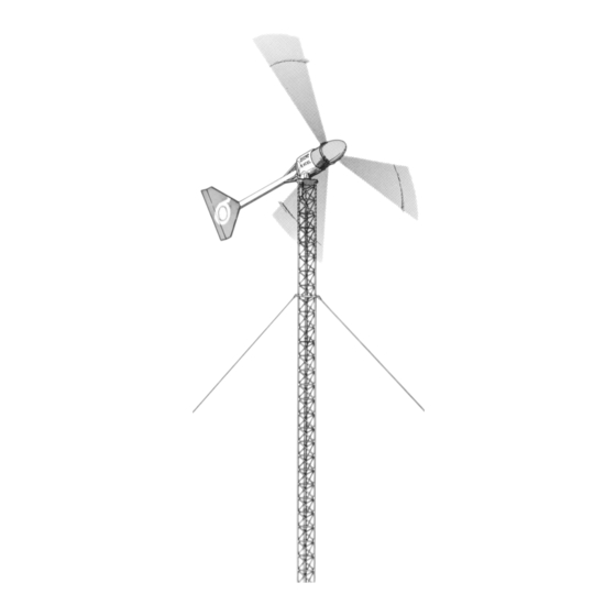
BWC EXCEL 10
Wind Turbine &
Powersync II
Grid-Intertie Inverter
Revision 2.0
April 2014
Part # MANXLS
Bergey Windpower Co.
2200 Industrial Blvd.
Norman, OK 73069 USA
TEL: 405-364-4212
FAX: 405-364-2078
E-mail:
sales@bergey.com
Web
Site:www.bergey.com
Table of
Contents
Previous
Page
Next
Page
1
2
3
4
5
Advertisement
Table of Contents
Need help?
Do you have a question about the Powersync II and is the answer not in the manual?
Ask a question
Questions and answers
Related Manuals for Bergey Powersync II
Wind Turbines Bergey BWC EXCEL 10 Owner's Manual
Wind turbine & powersync ii grid-intertie inverter (37 pages)
Wind Turbines Bergey 24 VDC B Owner's Manual
24 vdc battery charging system (24 pages)
Wind Turbines Bergey Tilt Tower Installation Manual
(40 pages)
Wind Turbines Bergey XL-15 Installation Quick Manual
(28 pages)
This manual is also suitable for:
Bwc excel 10
Table of Contents
Print
Rename the bookmark
Delete bookmark?
Delete from my manuals?
Login
Sign In
OR
Sign in with Facebook
Sign in with Google
Upload manual
Upload from disk
Upload from URL


Need help?
Do you have a question about the Powersync II and is the answer not in the manual?
Questions and answers