Table of Contents
Advertisement
Quick Links
Operation, Installation and Service Manual
Original Documentation / Keep for Future Reference
GYRO
1
GYRO
2
GYRO
3
M AGN
COM P
Heading Management System Type 4994-AB/AC
with Switch-Over Unit Type 4932
056360/E, 04994-0128-02, 27 Oct 2016
Woltmanstr. 19 • D-20097 • Hamburg, Germany
Tel.: +49-40-299 00-0 • Fax: +49-40-299 00-146 • E-mail: service.eu@sperry.ngc.com
DISPLAY DATA
246.8
SPEED
AUTO
12.8 kn
246.7
M ONITOR
Hdg. Diff
Off Hdg.
246.8
10°
10°
Gyro 1
Set Hdg.
Gyro 2
246.0
ALARM
247.0
NO ACTIVE
ALARM
NAVITWIN IV
for GAS support
Northrop Grumman Sperry Marine B.V.
Advertisement
Table of Contents

Summary of Contents for NORTHROP GRUMMAN NAVITWIN IV
- Page 1 Heading Management System Type 4994-AB/AC for GAS support with Switch-Over Unit Type 4932 056360/E, 04994-0128-02, 27 Oct 2016 Northrop Grumman Sperry Marine B.V. Woltmanstr. 19 • D-20097 • Hamburg, Germany Tel.: +49-40-299 00-0 • Fax: +49-40-299 00-146 • E-mail: service.eu@sperry.ngc.com...
- Page 2 Any technical content should be verified with NGSM BV. Sperry Marine, with major engineering and support offices in New Malden, England, and Hamburg, Germany, is part of the Northrop Grumman Navigation & Maritime Systems Division N&MSD. Revision Record Rev.
-
Page 3: Table Of Contents
NAVITWIN IV 056360/E Contents Safety Instructions Safety Notice Conventions ............... vii General Safety Information for the Operator ........viii General Safety Information for Service Personnel ........x Chapter 1: Introduction System Information .................. 1-1 Intended Use ....................1-1 Not Intended Use..................1-1 Design and Main Features................ - Page 4 Viewing Active Alarms ................4-6 Viewing of Internal Alarms ................4-6 Viewing of External Alarms ................. 4-6 Alarm messages ..................4-7 Internal Alarms (from NAVITWIN IV) ............4-7 External Alarms (from NAVIGAT Compasses) ..........4-11 Chapter 5: Scheduled Maintenance Maintenance by Shipboard Personnel ............ 5-1 Chapter 6: Installation Mechanical Installation................
- Page 5 Chapter 8: Troubleshooting General Troubleshooting Instructions............. 8-1 NAVITWIN IV....................8-1 Switch-Over Unit, Type 4932............... 8-2 Location of Parts on the NAVITWIN IV PCB ........... 8-3 Diagnostic LED Indicators ................8-4 Connectors....................8-5 Exchangeable Components ................ 8-5 Location of Parts on the Switch-Over Unit PCB........8-6 Diagnostic LED Indicators ................
- Page 6 056360/E NAVITWIN IV...
-
Page 7: Safety Instructions
NAVITWIN IV 056360/E Safety Instructions Safety Notice Conventions The following safety notice conventions are followed throughout this manual: A Danger notice contains an operating or main- DANGER tenance procedure, practice, condition, state- ment, etc., which, if not strictly observed, will result in injury or death of personnel. -
Page 8: General Safety Information For The Operator
CAUTION Risk of erroneous operating conditions through inaccurate alignment When the NAVITWIN IV is used in a system with the fiber-optic gyrocom- pass NAVIGAT 2100 / NAVIGAT 3000: At each new alignment (restart) of the NAVIGAT 2100 / NAVIGAT 3000, make sure that the FOG aligns correctly, using valid speed and position data. - Page 9 NAVITWIN IV 056360/E Note The NAVITWIN IV provides a serial bidirectional interface for a centralized alarm management system (CAM) according to DNV class notation NAUT-OC, NAUT-AW, NAUT_OSV. The CAM functionality is available from software version: NAVITWIN IV 4994-1091, Rev. E, 1.346, NAVIGAT X MK1 4914-1290, Rev.
-
Page 10: General Safety Information For Service Personnel
General Safety Information for Service Personnel WARNING Risk of electrical shock or burn Always make sure that the power supplies for the NAVITWIN IV and Switch-Over Unit are switched off and safeguarded against accidental switching-on, when wiring up the system. - Page 11 USB connection is recommended. When SUSI is installed under Windows 10™, the UpdateFlash mode via USB port is not available for the NAVITWIN IV CDU. Note The exemplary screens in the FlashUpdate mode procedure present are produced with the SUSI application installed under Windows XP™.
- Page 12 056360/E NAVITWIN IV...
-
Page 13: Chapter 1: Introduction
The Heading Management System NAVITWIN IV is a central control and display device for multi-compass systems for the maritime navigation of vessels. The NAVITWIN IV can be configured to perform a number of different functions such as: • Heading Source Selector •... -
Page 14: Design And Main Features
NAVIGAT 2100 (certificate no. 94 416-10 HH, 94 426-10HH) and NAVIGAT 3000 (certificate no. 37 757-12 HH, 37 957-12 HH). The NAVITWIN IV is compliant with the requirements of DNV rules for Ships Pt.6 Ch.8 and Ch.20 with regard to distribution of heading infor- mation. -
Page 15: Switch-Over Unit, Type 4932
Through control signals from the NAVITWIN IV, the SOU may be put in either one of three source selection modes: G1: Connects the outputs to the inputs from source “G1” . -
Page 16: Standard System Configurations
056360/E NAVITWIN IV 1.3 Standard System Configurations The NAVITWIN IV with Switch-Over Unit type 4932 is an integral part of Sperry Marines standard single, dual and triple gyrocompass configura- tions with NAVIGAT X MK1, X MK2 gyrocompasses and NAVIGAT 2100 NAVIGAT 3000 FOGs. -
Page 17: Dual Navigat Gyrocompass Systems
Switch-Over Unit to distrib- ute data from the compasses to external equipment. At the NAVITWIN IV, either one of the gyrocompasses may be activated to become the heading reference for external equipment, such as head- ing control systems, RADAR, compass repeaters etc. -
Page 18: Triple Navigat Gyrocompass Systems
Switch-Over Units to distribute data from the compasses to external equipment. At the NAVITWIN IV, any of the gyrocompasses may be activated to become the heading reference for external equipment, such as heading control systems, RADAR, compass repeaters etc. -
Page 19: Support For Gas According To Dnv Naut-Aw
056360/E 1.4 Support for GAS according to DNV Naut-AW The NAVITWIN IV may act as part of a grounding avoidance system (GAS) according to DNV class notation Naut-AW. For this purpose, the NAVITWIN IV in GAS mode provides a dedicated GAS serial data output for connection to a GAS-enabled track control or integrated navigation system (INS). - Page 20 act generating substitute heading after failure of active gyro run GAS mode switch to secondary set GAS status hdg source relay active start secondary gyro hdg status relay gyro1/gyro2 available AND difference status relay gyro/gyro3 between last active and generate substitue hdg status relay gyro1/magnet secondary hdg below GAS RS-422 output 1...
-
Page 21: Technical Data
NAVITWIN IV 056360/E 1.5 Technical Data NAVITWIN IV Environmental Requirements ambient temperature, operation - 15 to + 55° C ambient temperature, storage - 25 to + 70° C protection grade IP 23 to DIN EN 60529 environmental conditions / EMC in accordance with IEC 60945, equipment category “protected... - Page 22 056360/E NAVITWIN IV Dimensions and Weight (Forts.) PN 74858 (in housing with bracket) width 350 mm max. height (unit in 150 mm vertical position) max. depth (unit in 130 mm horizontal position) weight 2.15 kg approx. Data Inputs true heading (3 x)
- Page 23 NAVITWIN IV 056360/E Data Outputs • serial data RS-422 output 1 if available, all of: gyrocompass heading • serial data TTL output magnetic compass heading rate of turn heading reference status comp. mon. op. data • serial data RS-422 output 2...
-
Page 24: Switch-Over Unit, Type 4932
056360/E NAVITWIN IV Switch-Over Unit, Type 4932 Environmental Requirements ambient temperature, operation - 15 to + 55° C ambient temperature, storage - 25 to + 70° C protection grade IP 23 to DIN EN 60529 environmental conditions / EMC in accordance with IEC 60945, equipment category “protected... - Page 25 NAVITWIN IV 056360/E Data, Status and 12 V Supply Inputs from NAVITWIN IV if available, all of: NAVITWIN serial data (from NAVITWIN RS-422 output 1) gyrocompass heading magnetic compass heading rate of turn heading reference status comp. mon. op. data status G1/G2 (or G/G3) hdg.
-
Page 26: Declaration Of Conformity
Note The current issue of the detailed Marine Equipment Directive EC Declaration of Conformity of Northrop Grumman Sperry Marine B.V. Hamburg is part of the client CD stock no. 56 800. For further details please contact: Northrop Grumman Sperry Marine B.V. Hamburg... -
Page 27: Chapter 2: Operation
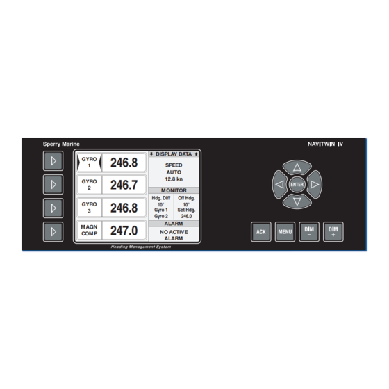
NAVITWIN IV 056360/E Chapter 2: Operation 2.1 Display and Operating Keys Figure 2-1: NAVITWIN IV operating unit DISPLA Y DATA GYRO 246.8 SPEED AUTO 12.8 kn GYRO 246.7 MONIT OR Hdg. Diff Off Hdg. GYRO 246.8 10° 10° Gyro 1 Set Hdg. -
Page 28: External Control Devices
(central dimming). 2.3 Power-up Sequence The NAVITWIN IV is not equipped with a power switch. The device pow- ers up as soon as supply power is applied to the gyrocompass system: Upon power up, the startup screen is shown and the initial system test is executed. -
Page 29: Selecting The Active Heading Source
2.4 Selecting the active heading source WARNING Limited data accuracy during settling time NAVITWIN IV permits to activate a heading source as soon as valid heading data is received from the respective device. Make sure that a gyrocompass has settled before using its heading as the reference for heading control systems, RADAR, ECDIS, etc. -
Page 30: Selecting Additional Display Data
056360/E NAVITWIN IV 2.5 Selecting additional display data The data display window shows a selection of additional data received via the heading source inputs or the GPS/Auto input. Depending on the data available, the operator may select one of up to five data screens to be displayed in the display data window. -
Page 31: Adjusting The Illumination Brightness
NAVITWIN IV 056360/E The selected data group is displayed until another group is selected. Upon power-up, the NAVITWIN IV displays the screen which was selected when the device was last powered down, if the respective data is available. 2.6 Adjusting the illumination brightness... -
Page 32: Optional Functions
A remotely muted alarm remains in the pending (unacknowledged) state. Note The alarm is indicated as pending in the alarm window until the alarm is acknowledged locally at the NAVITWIN IV or the cause of the alarm is eliminated. Resetting/Acknowledging a Central Watch Alarm... -
Page 33: Operating Menu
Note When the menu mode is active and no key is pressed for more than 30 seconds, the NAVITWIN IV automatically returns to normal operational mode. In the menu mode, the source selector keys are disabled and the bright- ness level cannot be adjusted. -
Page 34: Navigating The Menu
056360/E NAVITWIN IV Navigating the Menu In the menu mode, the operator may navigate through the menu using the Right, Left, Up and Down arrow keys. If sub-menus are present below a given menu level, a cursor ( ) at the left of the window indicates the current position within the menu. -
Page 35: Selecting Parameter Settings
NAVITWIN IV 056360/E Selecting Parameter Settings In a number of sub-menus, the operator is expected to select parameter settings from a list of available options. Radio buttons next to the items in the option list indicate that one and only one of the available options can be selected: = selected, = deselected. -
Page 36: Editing Parameter Values
056360/E NAVITWIN IV Editing Parameter Values In a number of sub-menus, parameters are set by editing a numerical value or an alphanumerical string. To edit a parameter value in the respective sub-menu: VALUE: VALUE 00000 With the Up/Down arrow keys, edit the character at the current cursor position. -
Page 37: Off Heading Monitor Settings
056360/E 2.10 Off Heading Monitor Settings The NAVITWIN IV can monitor the difference between the actual head- ing from the active source and the set heading order in automatic steer- ing modes. The set heading may either be received automatically from a heading or track control system or may be entered manually. -
Page 38: Heading Diff. Monitor Settings
056360/E NAVITWIN IV 2.11 Heading Diff. Monitor Settings NAVITWIN IV can monitor the difference between any two of the availa- ble heading sources. Should this difference exceed the alarm threshold, the “Heading Diff. Alarm” is given. For compliance with NAUT-AW/OSV class requirements for offshore ser-... -
Page 39: Manual Settings Menu
Note Some manual settings have no direct effect at the NAVITWIN IV but will overwrite the corresponding values at the NAVIGAT X MK 1, MK 2 gyro- compasses, or NAVIGAT 2100 / NAVIGAT 3000 FOGs. - Page 40 056360/E NAVITWIN IV Figure 2-3: contd. from previous page Manual Settings (contd.) MAN. SETTINGS NAVIPRINT nav. data printer settings NAVIPRINT RATE OF TURN ACTIV SPEED ERR COR < BACK < BACK PAPER SPEED 60 mm/h 150 mm/h 600 mm/h HEADING 30°...
-
Page 41: Manual Settings - Parameters
056360/E Manual Settings – Parameters SPEED Sets the speed input parameters. This setting is effective for the NAVITWIN IV internally and for all con- nected compasses evaluating the NAVITWIN IV op. data. SPEED MODE Selects the speed input mode. Settings: The actual speed value is entered manually. - Page 42 180°00.00’ W – 180°00.00’ E MAG VARIATION (Magnetic Variation) Sets the magnetic variation input parameters. This setting is effective for the NAVITWIN IV internally and for all con- nected compasses evaluating the NAVITWIN IV op. data. AUTO Selects the magnetic variation input mode.
- Page 43 ±70° scale to show ±70°. Standard setting for ±70° steering gears. RATE OF TURN Sets the rate of turn input parameters. This setting is only effective for connected compasses evaluating the NAVITWIN IV op. data. Manual Settings Menu 2-17...
- Page 44 Selects the North speed error correction mode for the connected gyro- compasses. This setting is effective only for NAVIGAT X MK 1 and NAVIGAT X MK 2 gyrocompasses, as the NAVITWIN IV merely enables or disables the error correction at the compasses. Error Correction...
-
Page 45: User Setup
NAVITWIN IV 056360/E 2.13 User Setup The User Setup menu provides access to settings which the operator may need to alter only occasionally. User Setup – Overview Figure 2-4: USER SETUP User Setup DATE & TIME date and time settings DATE &... -
Page 46: User Setup - Parameters
056360/E NAVITWIN IV User Setup – Parameters DATE & TIME Sets the date and time input parameters. AUTO Selects the date and time input mode. Settings: ON (option checked) Date/time are read automatically from the serial data input OFF (option unchecked) The current date and time are entered manually MAN. - Page 47 NAVITWIN IV 056360/E LCD COLOR Selects the daylight colour scheme. Settings: GRAY STYLE Black text and window borders, coloured window backgrounds; main window background is gray. BLUE STYLE Black text and window borders, coloured window backgrounds; main window background is blue.
- Page 48 056360/E NAVITWIN IV 2-22 User Setup...
-
Page 49: Chapter 3: Grounding Avoidance System (Gas)
NAVITWIN IV 056360/E Chapter 3: Grounding Avoidance System (GAS) The NAVITWIN IV may be incorporated into a grounding avoidance sys- tem (GAS) according to DNV class notation NAUT-AW requirements. In this context, “grounding avoidance system” refers to the whole of all... -
Page 50: Sequence Of Events And Actions
GAS threshold in the service setup. 2. Event: The active heading source Gyro 1 fails (loss of heading data). NAVITWIN IV immediately takes over the management of the com- pass system. Failure of active source triggers immediate GAS head- ing substitution at the NAVITWIN IV‘s GAS serial data output. - Page 51 GAS heading substitution is completed. To prevent sudden rudder actions, the NAVITWIN IV performs a soft transition at the GAS serial data output from the last known heading of the failed source to the actual heading from the secondary source: The difference (if any) between the two headings at the time of fail- ure of the active source is gradually reduced.
- Page 52 GAS mode is aborted immediately. 4. Action: Mute/acknowledge alarms. Mute/acknowledge any alarms which haven’t been acknowledged already. As alarms at the NAVITWIN IV, do not automatically clear when the GAS mode is triggered. When the manual steering mode has been selected, the track steering mode may now be resumed.
-
Page 53: Chapter 4: Alarm System
Monitor functionality is mandatory to prevent the CAM interface from transmitting heading difference and off heading alarm sentences, see “Internal Alarms (from NAVITWIN IV)” on page 4-7 for details. The NAVITWIN IV provides a serial bidirectional interface for a... -
Page 54: Alarm Indication
4.2 Alarm Indication Note The NAVITWIN IV is able to display alarms from the NAVITWIN IV itself (= „internal alarms“) and from the connected gyrocompasses (= „external alarms“). The indication and handling of internal and external alarms is handled differentially. -
Page 55: Visual Alarm Indication
NAVITWIN IV. Depending on whether the CAM is active or inactive (respectively not present), the NAVITWIN IV alarm window indication of the external alarms is handled differently. See “Acknowledging External Alarms at NAVITWIN IV” on page 4-11 for details. Alarm Indication... -
Page 56: Acknowledging Alarms/Muting The Audible Alarm
When the cause of an EXTERNAL alarm no longer exists, the alarm is CLEARED automatically from the NAVITWIN IV alarm window, even if not acknowledged by the operator. Note The NAVITWIN IV does not keep a history of past (inactive) alarms. Acknowledging Alarms/Muting the Audible Alarm... -
Page 57: Alarm Mute From External Device
NAVITWIN IV 056360/E Alarm Mute from External Device The NAVITWIN IV possesses a “Mute” output (relay contact) to mute an Note audible alarm sounded by an external device (e.g. an alarm panel or central alarm management system) in response to an alarm condition occurring at the NAVITWIN IV. -
Page 58: Viewing Active Alarms
056360/E NAVITWIN IV 4.4 Viewing Active Alarms Viewing of Internal Alarms If more than one active INTERNAL alarm is present at one time, all active internal alarms are indicated AUTOMATICALLY and the number of active alarms is increased. The total number of internal alarms and the index number of the cur- rently displayed internal alarm are shown in the alarm window title bar. -
Page 59: Alarm Messages
If the system is configured to read back the selection status from the Switch-Over Unit, an alarm is also given when the heading source selec- tion at the NAVITWIN IV differs from the status of the Switch-Over Unit. Table 4-1:... - Page 60 056360/E NAVITWIN IV Error Displayed Mes- Cause Corrective Action sage TIMEOUT No valid set heading Check whether the SET HDG data are received heading control sys- (timeout set from the heading tem provides valid set heading) control system. heading. Check interface and settings.
- Page 61 NAVITWIN IV. source selection, acti- vate different sources in turn and compare active heading as shown at NAVITWIN IV with indication at repeaters connected to Switch- Over Unit. OFF HDG The difference Determine the cause ALARM *...
- Page 62 NAUT-OSV. ** The CHANGEOVER GYRO message is the only WARNING message of the NAVITWIN IV system. In contrast to all alarm messages, the change- over warning message is indicated with a yellow title bar in the alarm window alternately flashing with the message text.
-
Page 63: External Alarms (From Navigat Compasses)
NAVIGAT X MK 2 gyrocompass, or by a NAVIGAT 2100 or a NAVIGAT 3000 fiber-optical gyrocompass. These external alarms are displayed and may be acknowledged at the NAVITWIN IV. Generally, for an external alarm, two lines of text are indicated in the NAVITWIN IV alarm window: •... - Page 64 • When CAM is INACTIVE and an external alarm is acknowledged locally at the respective gyrocompass, the alarm indication at the NAVITWIN IV is cleared automatically and the alarm is NOT longer present in the NAVITWIN IV alarm list. •...
- Page 65 NAVITWIN IV 056360/E Error Displayed Mes- Cause Corrective Action sage SPEED 2 FAIL NAVIGAT 2100 & Check interface/con- COMPASS NAVIGAT 3000: nection between the NAME No data received NAVIGAT FOG and the (speed 2 failure) from serial speed speed data source.
- Page 66 056360/E NAVITWIN IV Error Displayed Mes- Cause Corrective Action sage AC SUPPLY FAIL NAVIGAT X MK 1: Check power supply to COMPASS AC (main) power compass NAME supply failure. NAVIGAT X MK 2: Main DC power sup- ply failure. DIV BY ZERO Invalid calculation Restart system.
- Page 67 NAME the NAVITWIN IV. connection between (NAVITWIN IV Common parame- the NAVITWIN IV and communica- ters in Manual Set- the compass monitor tions error) tings / User Setup interface of the NAVI- menus will not be GAT gyrocompass.
- Page 68 056360/E NAVITWIN IV Error Displayed Mes- Cause Corrective Action sage MAG VAR FAIL No valid magnetic Acknowledge the COMPASS variation data alarm. NAME received in mag- Check whether the (magnetic varia- netic variation auto magnetic variation tion failure) mode. source provides valid data to the gyrocom- pass.
- Page 69 NAVITWIN IV 056360/E Error Displayed Mes- Cause Corrective Action sage EXT. ERR. NN Software of con- Update NAVITWIN IV (external error nected gyrocom- software. no.) pass is more current than the NAVITWIN IV soft- ware. Repeated sequence of displayed messages, causes and correc- –206...
- Page 70 056360/E NAVITWIN IV 4-18 Alarm messages...
-
Page 71: Chapter 5: Scheduled Maintenance
A visual inspection of cables and connectors should be carried out regu- larly to detect any signs of damage or deterioration. The NAVITWIN IV’s front plate should be cleaned when necessary, using only soap or a mild detergent applied with a damp cloth. Wipe dry with a cloth or towel. - Page 72 056360/E NAVITWIN IV Maintenance by Shipboard Personnel...
-
Page 73: Chapter 6: Installation
6.1 Mechanical Installation NAVITWIN IV Console Mounting To mount the NAVITWIN IV directly in a console panel (without console frame) a panel cutout is required as shown in dimension drawing 4994- 0112-02 (in the appendix). Suitable fasteners for console mounting are provided in the installation kit 22596. -
Page 74: Switch-Over Unit, Type 4932
When not installed in a bridge console, the Switch-Over Unit is to be mounted vertically (bulkhead mounting), with the cable inlets facing down. Inside a bridge console, the NAVITWIN IV may be installed verti- cally, horizontally or inclined. Make sure to observe the specified magnetic clearances. -
Page 75: Magnetic Compass Heading Calibration
- the steering magnetic compass is exchanged or newly adjusted. - the magnetic compass heading sensor is exchanged. - a fluxgate sensor is used and the NAVITWIN IV itself is exchanged. Ideally, the magnetic compass heading displayed at the NAVITWIN IV would exactly match the indication of the steering magnetic compass (at a mag. - Page 76 MAGN 000.8 COMP ues shown on the NAVITWIN IV display. At every full 10° of the steering magnetic compass heading (0°, 10°, …, 350°), note the display value.
- Page 77 NAVITWIN IV 056360/E Storing the magnetic compass heading calibration table 1. Call up the User Setup and go to ’Magn MAIN MENU Cal Tab | Enter Values’. Press ENTER. USER SETUP The calibration table entry screen is MAGN CAL TAB shown.
- Page 78 056360/E NAVITWIN IV Deleting entries from the magnetic compass heading calibration table When a complete new calibration is carried out, it is recommended to delete old entries from the calibration table first. Also, if the determined correction values are comparatively small, it is generally sufficient to enter only a few values for the headings where the largest deviations occur.
-
Page 79: Chapter 7: System Configuration
Chapter 7: System Configuration 7.1 Service Setup Menu The Service Setup provides access to the system parameters which con- figure the NAVITWIN IV according to the requirements of the installation at hand. Setup Access Code To prevent inadvertent or unauthorized changes to the system configu- ration, setup menus which are to be accessed by service personnel only are protected by access codes. -
Page 80: Service-Setup - Overview
056360/E NAVITWIN IV Service-Setup – Overview Figure 7-1: SERVICE SETUP Service Setup GYRO settings for Gyro inputs GYRO GYRO 1 INTERFACE TYPE NMEA-HDT/THS NMEA NAVIGAT PLATH BINARY COMPASS NAME GYRO GYRO 1 GYRO 2 GYRO 3 FOG 1 FOG 2... - Page 81 NAVITWIN IV 056360/E Figure 7-2: contd. from previous page Service Setup (contd.) GYRO 3/MAGN G3 INTERFACE INTERFACE TYPE NMEA-HDT/THS NMEA NAVIGAT PLATH BINARY COMPASS NAME GYRO GYRO 1 GYRO 2 GYRO 3 FOG 1 FOG 2 FOG 3 NAVISTAR USERNAME MAGN.
- Page 82 056360/E NAVITWIN IV Figure 7-3: contd. from previous page Service Setup (contd.) SERVICE SETUP RS422 settings for RS-422 outputs RS422 RS422 OUTP . 1 MAGN SELECT HCHDG HCHDT HCTHS HCHDM STATUS SELECT PPLAN PPNSD RS422 OUTP . 2 BAUDRATE 4800...
- Page 83 NAVITWIN IV 056360/E Figure 7-4: contd. from previous page Service Setup (contd.) RS422 OUTP . 3 TYPE NAVIPRINT NMEA BAUDRATE 4800 9600 19200 38400 GYRO SELECT XXHDT XXTHS MAGN. SELECT HCHDG HCHDT HCTHS HCHDM STATUS SELECT PPLAN PPNSD ALARM SELECT...
- Page 84 056360/E NAVITWIN IV Figure 7-5: contd. from previous page Service Setup (contd.) SERVICE SETUP CENTRAL DIMMING settings for central CENTRAL DIMMING PORT SETTINGS dimming input CENTRAL DIM ON INTERNALS RESTART NTIV GROUP ID < BACK ID: 1 – 99 DIM OFFSET value: -7 –...
-
Page 85: Service Setup - Parameters
NAVITWIN IV 056360/E Service Setup – Parameters GYRO Configures the Gyro and magnetic compass heading inputs. GYRO 1 Configures the Gyro 1 input. INTERFACE TYPE Selects the interface protocol for the Gyro 1 input. Settings: The input is disabled NMEA-HDT/THS The input reads the NMEA $--HDT or $--THS sentence. - Page 86 056360/E NAVITWIN IV GYRO 2 Configures the Gyro 2 input. INTERFACE TYPE Selects the interface protocol for the Gyro 2 input. Settings: The input is disabled. NMEA-HDT/THS The input reads the NMEA $--HDT or $--THS sentence. NMEA NAVIGAT The input reads NMEA data from a Sperry NAVIGAT X MK 1, X MK 2, NAVIGAT 2100 or NAVIGAT 3000 gyrocompass.
- Page 87 NAVITWIN IV 056360/E GYRO3/MAGN Configures the Gyro 3 and the magnetic compass heading inputs. G3 INTERFACE Configures the Gyro 3 input. INTERFACE TYPE Selects the interface protocol for the Gyro 3 input. Settings: The input is disabled. Select this setting if the G3/MAG input is used to receive an NMEA magnetic compass heading sentence.
- Page 88 056360/E NAVITWIN IV MAGN. COMP . (Magnetic Compass) Configures the magnetic compass heading input. INTERFACE TYPE Selects the interface and protocol for the magnetic compass heading input. Settings: The input is disabled. HCHDG The input reads the NMEA $HCHDG sentence via the G3/MAG interface.
- Page 89 NAVITWIN IV 056360/E SET HDG./GPS (Set Heading/GPS) Configures the Set Hdg./GPS input. PROTOCOL Selects the interface protocol for the Set Hdg./GPS input. Settings: The input is disabled. NMEA 4800 The input reads NMEA data at 4800 Bd. (standard according to IEC 61162-1).
- Page 90 056360/E NAVITWIN IV RS422 Configures the serial data outputs. RS422 OUTP . 1 (Output 1) Configures the RS-422 output 1 and the Compass Monitor output (TTL to NAVIGAT compasses and Switch-Over Unit). MAGN. SELECT (Magnetic Select) Selects the output sentence for magnetic compass heading data.
- Page 91 NAVITWIN IV 056360/E RS422 OUTP . 2 (Output 2) Configures the RS-422 output 2 BAUDRATE Selects the output baudrate Settings: 4800 The output transmits at 4800 Bd. (standard according to IEC 61162-1). 9600 The output transmits at 9600 Bd. 19200 The output transmits at 19200 Bd.
- Page 92 056360/E NAVITWIN IV MAGN. SELECT (Magnetic Select) Selects the output sentence for the magnetic compass head- ing data. Settings: Magnetic compass heading is not transmitted. HCHDG The output transmits magnetic compass head- ing using the NMEA $--HDG sentence with talker ID “HC” .
- Page 93 4800 Bd., while the output baudrate settings remain selectable. Note The NAVITWIN IV provides a serial bidirectional interface for a centralized alarm management system (CAM) according to DNV class notation NAUT-OC, NAUT-AW. The CAM functionality is available from software version: NAVITWIN IV 4994-1091, Rev.
- Page 94 056360/E NAVITWIN IV XXROT Enables or disables the transmission of rate of turn data. Settings: on (option checked) The output transmits the rate of turn from the active gyro source, using the $--ROT sentence. The talker ID will be the same as received from the respective source.
- Page 95 The output is scheduled to connect the naviga- tion data printer NAVIPRINT. At the time of writing of this manual, the NAVITWIN IV does not yet support the NAVI- PRINT setting. ⇒ Selecting option NAVIPRINT voids all NMEA settings of the RS422 output 3 interface.
- Page 96 056360/E NAVITWIN IV GYRO SELECT Selects the output sentence for gyrocompass (true) heading. Settings: Gyrocompass heading is not transmitted. XXHDT The output transmits gyrocompass heading using the NMEA $--HDT sentence. The talker ID will be the same as received from the respective heading source.
- Page 97 NAVITWIN IV 056360/E STATUS Selects the output sentence for navigation status data (pro- prietary sentence). Settings: Navigation status data is not transmitted. PPLAN The output transmits nav. status data using the $PPLAN sentence. PPNSD The output transmits nav. status data using the $PPNSD sentence.
- Page 98 4800 Bd., while the output baudrate settings remain selectable. Note The NAVITWIN IV provides a serial bidirectional interface for a centralized alarm management system (CAM) according to DNV class notation NAUT-OC, NAUT-AW. The CAM functionality is available from software version: NAVITWIN IV 4994-1091, Rev.
- Page 99 ID will be “TI” . off (option unchecked) The output does not transmit rate of turn data. Configures the NAVITWIN IV as part of a grounding avoidance system (GAS) according to DNV. GAS ON Enables or disables the GAS functionality.
- Page 100 RS-422 central dimming input. off (option unchecked) Central dimming is disabled. GROUP ID Sets dim group ID to assign the NAVITWIN IV to the respective dim group. Selecting ID “00” lets the NAVITWIN IV accept any dim command received, regardless of group assignment.
- Page 101 If a Central Alarm Management (CAM) device is connected to the Note NAVITWIN IV, the ACK message will be received, regardless which input sentence is selected for the central dimming commands. Note For parallel usage of a Central Alarm Management System (CAM) and a Central Dimming Device, a multiplexer device must be used for the shared RS422 interface at J6.36 / J6.37 of the NAVITWIN IV.
- Page 102 056360/E NAVITWIN IV PORT SETTINGS Configures the status input ports. PORT 1 MODE Selects the function of status input port 1. Settings: EXT. DIM (+) (External Dimming) The port is used for external dimming through push buttons; brightness is increased one level when the input contact is closed.
- Page 103 NAVITWIN IV 056360/E 180° OFFSET Selects the applicable heading sources for the 180° Offset function Settings: GYRO 1 ON (option checked): Gyro 1 heading is reversed when 180° Offset is active. OFF (option unchecked): Gyro 1 heading is not reversed when 180° Offset is active.
- Page 104 056360/E NAVITWIN IV INTERNALS Accesses system-internal parameters. FACTORY SETTING Resets all configuration parameters to factory defaults. Settings: none Select “Factory Settings” and press the ENTER key followed by the MENU key to reset all configuration parameters to the factory defaults.
-
Page 105: Chapter 8: Troubleshooting
When servicing the NAVITWIN IV, take precautions to prevent electro- static discharge. Avoid touching any of the electronic circuitry. The NAVITWIN IV is a complex electronic device. In case of malfunction, it would neither be practical nor economical to carry out troubleshoot- ing and servicing in the field down to the level of individual circuit com- ponents. -
Page 106: Switch-Over Unit, Type 4932
056360/E NAVITWIN IV Switch-Over Unit, Type 4932 Although the Switch-Over Unit is a passive device, field service person- nel should limit troubleshooting to: • Visual inspection of mechanical components, the PCB and wiring. • Continuity checks of wiring connections. •... -
Page 107: Location Of Parts On The Navitwin Iv Pcb
NAVITWIN IV 056360/E 8.2 Location of Parts on the NAVITWIN IV PCB Figure 8-1 below shows the locations of the diagnostic LED indicators, connectors and exchangeable components on the NAVITWIN IV PCB. Figure 8-1: location of parts on the NAVITWIN IV PCB... -
Page 108: Diagnostic Led Indicators
Diagnostic LED Indicators As an aid in troubleshooting, a number of diagnostic LED indicators are provided on the NAVITWIN IV PCB. These indicate the presence of sup- ply voltages, activities on the serial data I/O lines and the current states of the status I/O ports. -
Page 109: Connectors
RS-422 outputs 1, 2 and 3 photocoupler/photo relay; mute output photocoupler/photo relay; heading diff. alarm photocoupler/photo relay; watch alarm trigger photocoupler/photo relay; power failure / general alarm photocoupler/photo relay; off heading alarm photocoupler/photo relay; GAS alarm output Location of Parts on the NAVITWIN IV PCB... -
Page 110: Location Of Parts On The Switch-Over Unit Pcb
056360/E NAVITWIN IV 8.3 Location of Parts on the Switch-Over Unit PCB Figures 8-2 and 8-3 below show the locations of the diagnostic LED indi- cators and the connectors on the Switch-Over Unit PCB. Figure 8-2: Location of LEDs on the... -
Page 111: Diagnostic Led Indicators
NAVITWIN IV 056360/E Diagnostic LED Indicators Table 8-1: Colour Indication Diagnostic LED CR 12 green lit in modes G1 and M indicators CR 13 green lit when +24 VDC supply power present CR 14 green lit in mode G2 CR 15... - Page 112 056360/E NAVITWIN IV Location of Parts on the Switch-Over Unit PCB...
-
Page 113: Chapter 9: Corrective Maintenance
Before exchanging the flash-memory chip, IC 9, record all parameter set- tings to be able to re-enter them manually, if required. The NAVITWIN IV keeps two separate copies of the system software, one in an onboard flash memory and the other on the exchangeable software flashboard 20732. - Page 114 In case of a console or frame-mounted device, reattach the back cover and mount the NAVITWIN IV in the console. In case of a device in housing with bracket, insert the NAVITWIN IV in the housing and screw on the back cover.
- Page 115 NAVITWIN IV 056360/E 11. When the software download is complete, the NAVITWIN IV automatically restarts. 12. If an “EEPROM DATA INVALID” message is shown, the new soft- ware requires the setup mem- ory to be restored to factory settings. Press the ACK key to continue the power-up sequence.
-
Page 116: Uploading Software From A Pc Using Susi
SUSI on a laptop or PC. The upload is carried out via an RS-232 or a USB connection using SUSI‘s UpdateFlash mode. If you are using a USB con- nection, you must also install the NAVITWIN IV USB device driver included with SUSI. -
Page 117: Upload Procedure
3. Reconnect the 50-pin connector cable to the NAVITWIN IV but do not yet power-up the device again. 4. If a flashboard is installed in the NAVITWIN IV, remove it before pro- ceeding with the upload. Should a flashboard remain installed during the upload, its contents will be copied to the onboard flash memory when the system is restarted, i.e. - Page 118 SUSI‘s update tab opens automatically, displaying the Update Flash mode controls: 10. Plug in a USB standard cable at the PC and at the NAVITWIN IV‘s USB port (J10).an USB or RS-232 connection cable at the PC . If using the USB port, a standard USB connection cable is required, carrying type A and type B male connectors at the computer’s and...
- Page 119 13. Now, power up the NAVITWIN IV while keeping the MENU key pressed. This will prevent the device from entering normal operation and put it in the software update mode.
- Page 120 20. Check that the new software version is shown on the startup screen. 21. If no flashboard was installed originally in the NAVITWIN IV, skip to step 27 below. Otherwise, reinsert the flashboard into its socket now, while leaving the NAVITWIN IV powered up.
- Page 121 29. In case of a console or frame-mounted device, reattach the back cover and mount the NAVITWIN IV in the console. In case of a device in housing with bracket, insert the NAVITWIN IV in the housing and screw on the back cover.
-
Page 122: Replacing The Rs-422 Output Driver Ic
056360/E NAVITWIN IV 9.2 Replacing the RS-422 Output Driver IC The RS-422 output driver, IC 4, is a socketed 16-pin DIL chip. If failure or malfunction of the RS-422 outputs is attributed to a defective driver IC, the chip can be exchanged against a new one. -
Page 123: Chapter 10: Navitwin Iv Spare Parts
NAVITWIN IV 056360/E Chapter 10: NAVITWIN IV Spare Parts 10.1 Illustrated Parts List (IPL) Overview Table 10-1: Spare Part Name Stock No. IPL of system Flashboard (flash- 020732-0000-000 component spare parts memory card), pre-programmed with system software Illustrated Parts List (IPL) Overview... - Page 124 056360/E NAVITWIN IV 10-2 Illustrated Parts List (IPL) Overview...
-
Page 125: Abbreviations
NAVITWIN IV 056360/E Abbreviations Note The following list contains abbreviations and shortcuts used in this man- ual and in displayed text of CDU menus. 1x1 frame Standard frame 96x96 mm 6 step/° scale measure setting of servomotor A/DO-160 Section A, DO-160E, Environmental Conditions and... - Page 126 056360/E NAVITWIN IV Control and Display Unit Course over ground COMP Compass Comp. Mon. Compass monitor CONST. Constant contd. Continued CORR. Correction cos. Cosine Carriage return D00 - D32 (D-Code, = Fault code) Digital analogue converter Direct Current D-Code Fault code (D00 - D32)
- Page 127 NAVITWIN IV 056360/E Environmental conditions EM-Log Electromagnetic (speed) log European Norm ERR.STAT.BITS Validity check of fiber-optic sensor data status electrostatic discharge Ext Status In External status input port (TB 3.11) ext. External Ext. Sel. External selector switch Fiber optic interface unit (synonym for IPSU)
- Page 128 056360/E NAVITWIN IV GPS/AIS Global Positioning System / Automatic Identification System Gross tonnage Heading control system Heading, Magnetic Hdg. Heading hdg. Heading Hdg. Diff Heading Difference Alarm Hdg. Sel Heading selection; Selection of heading source device Hdg. Sel. Heading selection...
- Page 129 NAVITWIN IV 056360/E Illustrated Parts Data Illustrated Parts List IPSU Interface and power supply unit International Organization for Standardization Jack (connector) Kalman Filter Knot Knot Latitude Lat. Latitude lat. Latitude Liquid crystal display Light Emitting Diode LEHMK Lehmkuhl (transmission standard company Lehm-...
- Page 130 056360/E NAVITWIN IV MAGN. Magnet Magn. Cal. Tab Magnetic compass calibration table Magn. DEV Magnetic deviation Magn. VAR Magnetic variation MAN. Manually MarED Marine Equipment Directive max. Maximal Marine Equipment Directive Minute Minute min. Minimal MIPSU Modified Interface and Supply Unit Mechanical mode switch Mod.
- Page 131 NAVITWIN IV 056360/E NAVIGAT Nautic mile Nautic mile NMEA National Marine Electronics Association NMEA NMEA format 4800 Bd NMEA $--HDG NMEA $--HDG sentence NMEA $--HDM NMEA $--HDM sentence NMEA $--HDT NMEA $--HDT sentence NMEA Sup.FAST SuperFAST serial data output NMEA-GGA...
- Page 132 056360/E NAVITWIN IV Printed circuit board PL41 FOG variant PLATH Binary protocol of company C. Plath PLCC Plastic leaded chip carrier Position POSITION N No position QUICC Quad Integrated Communications Controller QUART Quad Universal Asynchronous Receiver and Transmit- Rudder angle calibrator...
- Page 133 NAVITWIN IV 056360/E South Second S/FAST M. Outp. Superfast / fast data output of magnetic compass heading SAT-Log Satellite (speed) log sc. Factor Scale factor Steering control unit Second Second SENS.D.M.OUTP. Output sentence format for magnetic compass head- ing at the sensor data output...
- Page 134 056360/E NAVITWIN IV Transmitting magnet compass TMC function Transmitting magnet compass function TSS1 TSS1 protocol; Heading, pitch, roll, and heave mes- sage in the commonly used TSS1 message format Transistor-transistor-logic TxD NMEA FAST Fast serial data output UART Universal asynchronous receiver transmitter...
- Page 135 NAVITWIN IV 056360/E X rate Roll rate X/Y rates Roll and pitch rates Y rate Pitch rate Z/DO-160 Section Z, DO-160E, Environmental Conditions and Test Procedures for Airborne Equipment Abbreviations...
- Page 136 056360/E NAVITWIN IV...
-
Page 137: Appendix
NAVITWIN IV 4994-0125-03 Magnetic Compass Calibration Table After installation of the NAVITWIN IV, please return a filled-out copy of Note the Setup Table to Sperry Marine for inclusion in the ship’s file. When permanent changes are made to the system configuration, please return an updated copy of the Setup Table to Sperry Marine. - Page 138 056360/E NAVITWIN IV Note All appended drawings are revision-controlled separately at Sperry Marine. In case of doubt, verify the current revision status of the draw- ings with Sperry Marine. This manual’s revision status does not change when the revision of an appended drawing changes.
- Page 139 Magn. Cal. Tab. _________ Enter Values: Use Cal. Tab. Version Info _________ LCD Color GRAY STYLE BLUE STYLE BLACK STYLE Northrop Grumman Sperry Marine B.V. (Representative Office) Woltmanstr. 19, D-20097 Hamburg, Germany Tel.: +49-40-299 00-0, Fax: +49-40-299 00-298, E-mail: service.de@sperry.ngc.com...
- Page 141 Service Station / Installer: Date / Signature: Note After installation of the NAVITWIN IV, please return a filled-out copy of the Setup Table to Sperry Marine for inclusion in the ship’s file. When permanent changes are made to the system configuration, please return an updated copy of the Setup Table to Sperry Marine.
- Page 142 HCHDT HCTHS HCHDM Status Select PPLAN PPNSD Alarm Select PPLAA/PPLAB/PPLAD ROT Out XXROT GAS ON Max. Hdg. Diff _________________ Time Constant _________________ Northrop Grumman Sperry Marine B.V. Woltmanstr. 19, D-20097 Hamburg, Germany Tel.: +49-40-299 00-0, Fax: +49-40-299 00-298, E-mail: service.de@sperry.ngc.com...
- Page 143 Individ. Name GYRO1 NAME: _________________ GYRO2 NAME: _________________ GYRO3 NAME: _________________ MAGN NAME: _________________ LCD Color GRAY STYLE BLUE STYLE BLACK STYLE Northrop Grumman Sperry Marine B.V. Woltmanstr. 19, D-20097 Hamburg, Germany Tel.: +49-40-299 00-0, Fax: +49-40-299 00-298, E-mail: service.de@sperry.ngc.com...
- Page 145 80.0 260.0 90.0 270.0 100.0 280.0 110.0 290.0 120.0 300.0 130.0 310.0 140.0 320.0 150.0 330.0 160.0 340.0 170.0 350.0 Northrop Grumman Sperry Marine B.V. (Representative Office) Woltmanstr. 19, D-20097 Hamburg, Germany Tel.: +49-40-299 00-0, Fax: +49-40-299 00-298, E-mail: service.de@sperry.ngc.com...
- Page 164 Sperry Marine Service: www.sperrymarine.com/offices Northrop Grumman Sperry Marine B.V. (Representative Office) Woltmanstr. 19 • D-20097 • Hamburg, Germany Tel.: +49-40-299 00-0 • Fax: +49-40-299 00-146 • E-mail: service.eu@sperry.ngc.com...
Need help?
Do you have a question about the NAVITWIN IV and is the answer not in the manual?
Questions and answers