Table of Contents
Advertisement
Quick Links
Advertisement
Table of Contents

Subscribe to Our Youtube Channel
Summary of Contents for BTG Visual-ICE
- Page 1 User Manual...
- Page 2 For assistance, contact: www.galilmedical.com USA: Galil Medical Inc., 4364 Round Lake Road, Arden Hills, MN 55112, USA. Telephone: +1 877 639 2796, Fax +1 877 510 7757 Galil Medical Inc., 4364 Round Lake Road, Arden Hills, MN 55112, USA. Telephone: +1 877 639 2796, Fax +1 877 510 7757 Obelis s.a., Boulevard Général Wahis 53, 1030 Brussels, Belgium.
-
Page 3: Table Of Contents
2.9.3 Power Control Knob 2.9.4 Needle Channels 3 NAVIGATING THE USER INTERFACE 3.1 Login Screen 3.2 Startup Screen 3.3 Procedure Screen 3.3.1 Navigation Tool Bar 3.3.2 Context Sensitive Help 3.3.3 User-Selected Self Help 3.3.4 Channel Controls 3.3.5 Channel Status Visual-ICE™ Cryoablation System... - Page 4 5.1 Configure Settings 5.1.1 Manual Software Update 5.1.2 Configure Ethernet 6 SYSTEM CARE and MAINTENANCE 6.1 System Installation 6.2 Cleaning 6.2.1 Cleaning the Visual-ICE System 6.2.2 Cleaning the Stylus 6.3 Service and Preventive Maintenance 6.4 Technical Information 6.5 System Disposal 7 TROUBLESHOOTING 7.1 Software Recovery 7.2 Electronics, Electrical and User Error Related Issues...
- Page 5 8.2 Storage Conditions 8.3 Transportation Conditions 8.4 Mechanical Specifications 8.5 External Gas Supply 8.6 Gas Cylinder Specifications 1.1 Accuracy of Displayed Values 8.7 Electrical Specifications 8.7.1 Electromagnetic Compatibility and Immunity (EMC and EMI) 9 REFERENCES 9.1 Patents 9.2 Trademarks 9.3 Contact 10 DISCLAIMER OF WARRANTY 10-1 Visual-ICE™ Cryoablation System...
- Page 6 List of Figures Figure 2-1. Visual-ICE Cryoablation System Front View Figure 2-2. Visual-ICE Cryoablation System Rear View Figure 2-3. Monitor Storage Compartment Figure 2-4. Visual-ICE Cryoablation System Needle Connection Panel Figure 2-5. Visual-ICE Cryoablation System Needle Channel Figure 4-1. Visual-ICE System Gas Connections Figure 4-2. Gas Cylinder Set-up Figure 4-3. EZ-Connect2 Dual Cylinder Adapter Figure 4-4. Locking Needle into Channel 4-11 Figure 4-5. MTS Connection 4-14 User Manual...
- Page 7 Table 4-1. Cryoablation Procedure Flow Table 4-2. Working Gas Pressures Table 5-1. Configure Settings Controls Table 8-1. Cable Lengths Table 8-2. Electromagnetic Emissions Table 8-3. Electromagnetic Immunity Table 8-4. Electromagnetic Immunity for Systems that are Not Life-supporting Table 8-5. Recommended separation distances between portable and mobile RF communications equipment and the Visual-ICE System Visual-ICE™ Cryoablation System...
- Page 8 List of Screens Screen 3-1. Login Screen Screen 3-2. Startup Screen Screen 3-3. Procedure Screen Screen 3-4. Navigation Tool Bar Screen 3-5. Channel Controls and Channel Status section Screen 3-6. Active Thaw Channel Status section Screen 3-7. Needle Tip Temperature Display Screen 3-8.
-
Page 9: Screen 3-15. Configure Settings
Screen 4-29. Advanced Temperature Sensor Controls 4-29 Screen 5-1. Configure Settings Screen 5-2. Software Update Confirmation Screen 7-1. Software Recovery Screen Screen 7-2. Invalid Configuration Message Visual-ICE™ Cryoablation System... - Page 10 This page intentionally left blank. viii User Manual...
-
Page 11: Symbols
Type BF Applied Part Unsafe Voltage. Electrical contacts greater than 40 V AC Power Switch Power On Power Off Authorized Representative in Do Not Discard ETL Product Listing Return to Galil Medical at end the European Community of service life Visual-ICE™ Cryoablation System... - Page 12 only Caution: Federal (USA) law restricts this device to sale by or on the order of a physician. Footnotes 1. EN ISO 15223-1:2016 Medical devices –Symbols to be used with medical device labels, labelling and information to be supplied – Part 1: General requirements 2.
-
Page 13: System Overview
Use of this device is restricted to use by or under the supervision of physicians trained in cryoablation procedures with a Galil Medical Cryoablation System. CAUTION. All new users must be trained on the use of the Visual-ICE™ Cryoablation System and cryoablation procedures prior to operating the system. Contact your local Galil Medical representative to schedule training. -
Page 14: Intended Use
The Galil Medical Visual-ICE Cryoablation System is intended for cryoablative destruction of tissue during minimally invasive procedures; various Galil Medical accessory products are required to perform these procedures. The Visual-ICE System is indicated for use as a cryosurgical tool in the fields of general surgery, dermatology, neurology (including cryoanalgesia), thoracic surgery (with the exception of cardiac tissue), ENT, gynecology, oncology, proctology, and urology. -
Page 15: Accessory Products Used To Conduct Cryoablation Procedures
1.3.2 Accessory Products Used to Conduct Cryoablation Procedures The following items used with the Visual-ICE System are sterile, single-use only devices. Do not re- sterilize or reuse. Galil Medical Cryoablation Needles: The Visual-ICE System is used only with Galil Medical •... -
Page 16: Indications
Indications The Visual-ICE Cryoablation System is indicated for use as a cryosurgical tool in the fields of general surgery, dermatology, neurology (including cryoanalgesia), thoracic surgery (with the exception of cardiac tissue), ENT, gynecology, oncology, proctology, and urology. This system is designed to destroy tissue (including prostate and kidney tissue, liver metastases, tumors, and skin lesions) by the application of extremely cold temperatures. -
Page 17: Warnings
Secure the safety cable at the end of the gas supply line to the console bracket on the Visual-ICE • System before connecting the gas supply line to the gas inlet. The safety cables provide backup protection if the gas supply lines become inadvertently disconnected from the system. -
Page 18: Precautions
• Do not use the Visual-ICE Cryoablation System if any moisture or condensation is present on the surfaces of the system. Powering up the system containing moisture or condensation could result in permanent damage to the electrical boards, causing the system to be inoperable. -
Page 19: Handling
Do not tilt the Visual-ICE Cryoablation System. • Lift the Visual-ICE System to clear any threshold that is higher than 2 cm. Two people, one on • each side, should use the handles to lift the system. -
Page 20: After Use
Cut the needle and MTS tubing and dispose of used needle and MTS in a biohazard container in • accordance with hospital and safety regulations. Clean the Visual-ICE System per the instructions in Section 6.2. Do not use cleaning agents such • as Betadine or bleach solution, which may damage the touch screen. -
Page 21: Potential Adverse Events
UPJ obstruction/injury, urethral sloughing, urethral stricture, urinary fistula, urinary frequency/urgency, urinary incontinence, urinary leak, urinary renal leakage, urinary retention/oliguria, urinary tract infection, vagal reaction, voiding complication including irritative voiding symptoms, vomiting, wound complication, and wound infection. Visual-ICE™ Cryoablation System... - Page 22 This page intentionally left blank. 1-10 User Manual...
-
Page 23: System Description
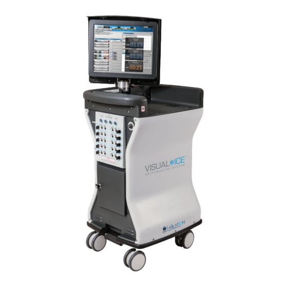
2 SYSTEM DESCRIPTION The Visual-ICE™ Cryoablation System is a mobile cryoablation system that contains ten needle connection channels (each supporting two needle ports), four Multi-Point Thermal Sensor sockets, one argon inlet connector, one helium inlet connector, a recessed 19-inch touch screen monitor, a mouse track pad, two USB ports, and an Ethernet port. -
Page 24: Figure 2-1. Visual-Ice Cryoablation System Front View
Figure 2-1. Visual-ICE Cryoablation System Front View Touch Screen Monitor Monitor Storage Compartment Mouse Track Pad Needle Connection Panel Power Control Knob Storage Compartment Brake Pedal Wheels (casters) User Manual... -
Page 25: Touch Screen Monitor
Figure 2-2. Visual-ICE Cryoablation System Rear View Argon Shutoff Valve Cooling Fan Argon Inlet Connector Helium Inlet Connector Cord Wrap Bracket Power Switch Ground Post (select countries) Gas Supply Line Clip Manual Vent Valve Rear Wheel Brake Pedal Touch Screen Monitor The cryoablation procedure is controlled through the use of the touch screen monitor. -
Page 26: Communication Ports
Three communication ports are located on the back panel of the monitor storage compartment (Figure 2-3). The Ethernet port allows connection of the Visual-ICE Cryoablation System to a Galil Medical • remote server for uploading reports and diagnostic data and for downloading software updates and User Manual updates. -
Page 27: Brake Pedal
Argon Shutoff Valve The Argon Shutoff Valve is used to turn the gas supply to the Visual-ICE Cryoablation System ON or OFF. It should be left in the GAS ON position and used to turn OFF argon gas only in an emergency. -
Page 28: Needle Connection Panel
Needle Connection Panel Figure 2-4. Visual-ICE Cryoablation System Needle Connection Panel Figure 2-5. Visual-ICE Cryoablation System Needle Channel MTS Connection Port Software Reset Power Control Knob Needle Channel Needle Port with Electrical Locking Bar Connection Channel Number 2.9.1 MTS Connection Ports Four MTS Connection Ports are located above the Needle Connection Channels. -
Page 29: Software Reset
2.9.2 Software Reset The Software Reset button is used to boot the Visual-ICE Cryoablation System into a recovery mode if the software becomes corrupted (reference Section 7.1). 2.9.3 Power Control Knob The Power Control Knob powers ON the Visual-ICE Cryoablation System in preparation for a procedure. - Page 30 This page intentionally left blank. User Manual...
-
Page 31: Navigating The User Interface
• OPTIONAL = optional or alternate step • The Visual-ICE™ Cryoablation System provides a graphical user interface that facilitates rapid communication between the user and the system through a touch screen interface. Login Screen When the system is powered on, the Login Screen appears after the boot-up process is complete (reference Section 4.1.1). -
Page 32: Startup Screen
Startup Screen After logging into the system, the Startup Screen displays several options. Screen 3-2. Startup Screen Table 3-1. Startup Screen Buttons Button Description Transition to the Procedure Screen to start a cryoablation Start Procedure procedure. Logout Log out of the system. View the contents of a report and export reports to a Galil Medical USB flash drive. -
Page 33: Procedure Screen
Procedure Screen The Visual-ICE System Procedure Screen provides a single-screen view to control and monitor a cryoablation procedure. The Procedure Screen is divided into sections for the Navigation Tool Bar, Context Sensitive Help, Channel Controls, Channel Status, Temperature Sensors, and Organ Map. -
Page 34: Navigation Tool Bar
Displays the working pressure of the argon and helium gases Indicator within the system. NOTE: The Visual-ICE System contains internal regulators that regulate the gas pressure to appropriate working limits. The pressure displayed on the Gas Indicator is the internal, regulated pressure and not the cylinder gas pressure. -
Page 35: Context Sensitive Help
(Test, Freeze, or Thaw) on this channel to activate that function on all needles simultaneously. Test button – Begins the Needle Integrity and Functionality Testing that is required prior to using any cryoablation needle. No other controls are enabled until needle testing is complete. Visual-ICE™ Cryoablation System... - Page 36 100% to 5% or to select “Stick” intensity. NOTE: The Visual-ICE System controls freeze intensity by adjusting the duration of argon flow over each 10 second block of time (e.g., 30% freeze intensity freezes for 3 seconds and idles for 7 seconds).
-
Page 37: Channel Status
The temperature display is updated every 2 seconds. NOTE: During the needle warming phase for CX-type needles, the channel status will display a rotating warming indicator Screen 3-7. Needle Tip Temperature Display Visual-ICE™ Cryoablation System... -
Page 38: Enlarge And Reposition Timers
3.3.6 Enlarge and Reposition Timers During a needle test, freeze, thaw, or idle phase, press the Timer button to enlarge the timer display (Screen 3-8). The enlarged Timer displays the channel number in the upper left corner of the timer window, elapsed time, and, when freezing, the selected freeze intensity. -
Page 39: Temperature Sensors
NOTE: A maximum of four sensor locations can be displayed on the graph at any one time. The four selected sensor locations can be from any of the connected MTS needles. Screen 3-10. Temperature Sensors section MTS sensor locations MTS Channel button Thermometer button Visual-ICE™ Cryoablation System... -
Page 40: Organ Map
Maximize button Button corresponding to 5 mm sensor location Triangle indicates coldest sensor Select the Scale button to adjust the graphical display of the temperature measurements such that the temperature throughout the entire procedure is visible. Select the Scroll button to display a scroll bar to scroll through the graphical data during the procedure. -
Page 41: Table 3-4. Organ Map Controls
Needle Lock button – Lock a needle in place on the organ map so that it may not be inadvertently moved. Clear All button – Clear all drawings and needle placements from the drawing canvas. Visual-ICE™ Cryoablation System 3-11... -
Page 42: View Reports
Screen 3-12. Procedure Report Example To view a report that has been saved to the Visual-ICE System, press the View Reports button from the Startup Screen (Screen 3-2). -
Page 43: Screen 3-13. View Reports Screen
The Export Report button displays a window to choose the Export File Type and File Name for exporting the report. Reports can be exported in HTML, PDF, or CSV formats. An additional option is available to export raw MTS data for further analysis. Screen 3-14. Export Report Screen Visual-ICE™ Cryoablation System 3-13... -
Page 44: Configure Settings
Configure Settings The Configure Settings Screen allows selection of settings used during a cryoablation procedure. Settings that may be changed include MTS Needle Locations, System, Procedure and Registration Settings and Units (reference Section 5.1). Control buttons have options for Calibrate Touch Screen, Manage Users, Manual Software Update, and Configure Ethernet (reference Section 5.1). -
Page 45: Service Screen
3-16). A confirmation message appears when the upload / download process has been successfully completed (Screen 3-17). Restart the Visual-ICE System following successful completion of a software update download to begin using the new software version. The current software version number is displayed in the upper right hand corner of the Startup Screen (Screen 3-2). -
Page 46: Screen 3-16. Remote Upload / Download Screen
Screen 3-16. Remote Upload / Download Screen Screen 3-17. Successful Upload / Download 3-16 User Manual... -
Page 47: System Operation
4 SYSTEM OPERATION Table 4-1 depicts the order and steps of the Visual-ICE™ Cryoablation System set-up and treatment procedure. Each step is described in detail in this chapter. Table 4-1. Cryoablation Procedure Flow • Confirm availability of gas, needles, and accessories Position Visual-ICE System and lock brake •... -
Page 48: System Set-Up
This power switch should remain ON at all times. The Visual-ICE System will not turn ON if this power switch is in the OFF position. 5. Confirm that the Argon Shutoff Valve on the Visual-ICE System is in the GAS ON position. Turn it to the GAS ON position, if needed. -
Page 49: Screen 4-1. Disabled Channel
A failure that prevents use of the system displays a message directing you to contact Galil Medical Customer Service (reference Section 7.7). If the Visual-ICE System software detects pressurized gas in the system and the gas supply is not connected, a message appears requesting you to vent the gas from the system. -
Page 50: Screen 4-3. Login Screen
To change text case, use the shift button on the virtual keyboard. NOTE: If you leave the user interface idle for a pre-set time with no activity, the Visual-ICE System software requires you to re-enter your password to unlock the user interface (reference Section 5.1). -
Page 51: Screen 4-5. Reset Password Challenge
Call Galil Medical Customer Service to receive the proper response to enter, then press the Login button (Screen 4-7). NOTE: This action does not reset your password. Screen 4-7. Emergency Login Visual-ICE™ Cryoablation System... -
Page 52: Connecting Gas Cylinders
1. Position the gas cylinder(s) close enough to the Visual-ICE System to ensure that the gas supply line is not stretched and does not present a trip hazard. 2. On the rear of the Visual-ICE System, ensure that the Manual Vent Valve is in the CLOSED position. -
Page 53: Figure 4-2. Gas Cylinder Set-Up
• Connect the end of the gas supply line to the argon inlet of the Visual-ICE System using the quick-connect connector. Visual-ICE™ Cryoablation System... -
Page 54: Figure 4-3. Ez-Connect2 Dual Cylinder Adapter
(Table 4-2). The Gas Indicator should indicate the pressure to be in the green range. If the system detects that the pressure reading for either gas cylinder is less than 50 psi, a message displays on the Navigation Tool Bar (Screen 4-8). Connect the gas cylinders to the Visual-ICE System. User Manual... -
Page 55: Gas Line Flushing
• Failure to operate the Visual-ICE System within the working pressure limits may affect the cryoablation procedure. If the system produces a continuous hissing sound, verify that the Manual Vent Valve is fully •... -
Page 56: Pre-Procedure Testing
2. Using aseptic technique, carefully remove the cryoablation needle from the package and place in a sterile work area. 3. Remove the connector cap, and then connect the needle to the Visual-ICE System needle connection panel (Figure 2-4). CAUTION. Do not kink, pinch, cut or pull excessively on the needle tubing. Damage to needle handle or tubing may cause the needle to become unusable. -
Page 57: Figure 4-4. Locking Needle Into Channel
Additionally, using needles of differing types in a channel may affect the accuracy of the Gas Indicator. CAUTION. If the Visual-ICE System detects that helium gas is connected, the system defaults to helium thaw mode and i-Thaw, FastThaw, and Cautery capabilities are disabled. -
Page 58: Screen 4-12. Needle Past Expiration Date Message
A dark gray channel button indicates a channel with needles connected. If the needle contains a memory chip, the Visual-ICE System automatically detects the type of needle being used, the lot number, and the expiration date of the product. If the system detects that the expiration date has passed, a message appears and gas flow to that channel is disabled. - Page 59 Needle Integrity and Functionality Test must be conducted again on that needle. NOTE: If a previously tested needle containing a memory chip is moved to a new channel during a procedure, the Visual-ICE System will recognize the needle has successfully completed the Needle Integrity and Functionality Test.
-
Page 60: Performing A Cryoablation Procedure
12. When using Multi-Point Thermal Sensors (MTS), prepare the desired number of sensors for testing. The Visual-ICE System supports use of four thermal sensors. Connect each thermal sensor to an MTS connection port by pushing the connector into the port. Ensure that the rectangular tongue on the MTS connector is aligned with the groove at the top of the connection port for proper MTS insertion (Figure 4-5). -
Page 61: Screen 4-14. Gas Time Remaining
8. To actively thaw the iceball, press the Thaw button on the channels containing needles to start the thaw phase. If the Visual-ICE System detects that helium gas is connected, the system defaults to helium thaw mode. If needles of mixed type (some helium thaw and some i-Thaw) are connected, the system also defaults to helium thaw mode. -
Page 62: Reports
NOTE: When thawing with CX-type needles, thawing is limited to a maximum of 7 needles simultaneously activated. Thawing with the FastThaw function is limited to a maximum of 4 needles simultaneously (reference Section 4.6.1 for instructions on using i-Thaw and FastThaw). OPTIONAL: To initiate a thaw phase on all needles simultaneously, press the Thaw button on the channel labeled ALL. -
Page 63: Screen 4-15. Export Report Screen
Screen 4-15. Export Report screen CAUTION. Use only a Galil Medical supplied USB flash drive with the Visual-ICE System. Do not use that flash drive for purposes unrelated to Visual-ICE System data and reports. 4. Press the Export button to begin exporting the file. Wait for confirmation before removing the USB flash drive from the system. -
Page 64: System Shutdown
7. Wait until the screen goes black. Turn the Power Control Knob to the OFF position. 8. Unplug the Visual-ICE System and wrap the power cord around the cord wrap on the rear of the system. -
Page 65: Changing Gas Cylinders During A Procedure
3. Close the Manual Vent Valve. 4. Slowly open the argon cylinder valve one quarter to one half of a turn. Allow pressure to build on the argon pressure gauge. Open the argon cylinder valve fully for sufficient argon flow. Visual-ICE™ Cryoablation System 4-19... -
Page 66: Dual Gas Cylinder Connection
Advanced Thaw Controls The Visual-ICE System provides options to select helium-free thawing (i-Thaw and FastThaw) and to conduct track ablation (Cautery). NOTE: i-Thaw, FastThaw and Cautery functions are only available when needles with that capability are connected. -
Page 67: Screen 4-18. Advanced Thaw Controls I-Thaw
4. When the threshold temperature for i-Thaw or FastThaw is reached, the channel status will display the estimated temperature range for the needle shaft (Screen 4-20). NOTE: The shaft temperature is displayed as a temperature range because tissue and procedural variables will affect the temperature. Visual-ICE™ Cryoablation System 4-21... -
Page 68: Cautery Control For Track Ablation
CAUTION. The Cautery function should not be initiated if the Active Zone Indicator is visible outside the patient’s skin. NOTE: While the Visual-ICE System is in cautery mode, freezing and thawing are not allowed on any other channels. NOTE: The Cautery function is not available on the channel ALL. -
Page 69: Screen 4-21. Cautery Confirmation Message
Only one needle per channel may activate the cautery function at a given time. NOTE: The Visual-ICE System uses a pre-set duration of 30 seconds for each cautery phase for 1.5 CX-type needles. This value is not adjustable, but the duration can be stopped in advance of 30 seconds by pressing the Stop button. -
Page 70: Cautery Control For 2.1 Cx Needles
• When the cautery function has terminated, the timer indicates the status as Stopped and the temperature display indicates that the needle is Cooling. 5. If desired, press the Start button to re-initiate track ablation on additional sections of the needle track. -
Page 71: Advanced Channel Controls
NOTE: This function is not available on the channel labeled ALL. You can only link channels that are on the same horizontal plane on the Needle Connection Panel (e.g., 1 and 2, 3 and 4, 5 and 6). Screen 4-25. Linked Channels Visual-ICE™ Cryoablation System 4-25... -
Page 72: Cycle Programming Control
3. Press the Unlink button (accessed by pressing and holding the Channel button) to remove the link between two channels so that each operates independently. 4.7.3 Cycle Programming Control 1. Press and hold the Channel button to enter Advanced Channel Controls for that channel. 2. -
Page 73: Screen 4-27. Cycle Sequence Controls
11. Repeat steps 1 to 10 to program additional channels. NOTE: Programmed sequences may be saved by selecting the Save Cycle button. Name the sequence, then press the Save button (Screen 4-27). Screen 4-27. Cycle Sequence Controls Visual-ICE™ Cryoablation System 4-27... -
Page 74: Screen 4-28. Saved Sequence Controls
To run a saved sequence, enter Advanced Channel Controls for the selected channel, press the Cycles button and press the Load Cycle button. Using the drop-down menu, select the saved sequence, press the Load button, then press the Go button (Screen 4-28). Screen 4-28. -
Page 75: Advanced Temperature Sensor Controls
OPTIONAL: Select a name to be displayed above the MTS channel location using the Needle Location drop-down menu. The list of needle names provided is derived from the list available in the Configure Settings Screen (reference Section 5.1) and is associated with the selected organ map. Visual-ICE™ Cryoablation System 4-29... - Page 76 This page intentionally left blank. 4-30 User Manual...
-
Page 77: Administrative Functions
The Configure Settings Screen allows you to change system settings used during a cryoablation procedure. A maximum of five (5) user accounts can be configured for each Visual-ICE™ System. Settings that may be changed include MTS Needle Locations, System, Procedure and Registration Settings and Units (reference Table 5-1). - Page 78 Setting Description Select the gas cylinder volume and units of measure according to the standard in the geographical region. The gas cylinder Cylinder Volume volume and units can only be changed by administrative or service personnel. Select the desired duration from 30 to 180 minutes that the Inactivity Timeout system can be inactive before requiring you to re-enter your password.
- Page 79 Information system history file. The time zone can be changed by administrative or service Time Zone personnel. The Visual-ICE System automatically adjusts for Daylight Saving Time. Pressure Units Select the units of pressure that the Gas Indicator displays. Select the temperature units that the Temperature Sensors Temperature Units section displays and graphs.
-
Page 80: Manual Software Update
This function is only available to administrative and service users. The Visual-ICE System may be configured to use a static IP address or work with a DHCP server to obtain the address dynamically. Consult the network administrator about proper network access prior to configuring the system. -
Page 81: System Care And Maintenance
The needle connection ports must remain completely dry at all times. 3. Ensure that cleaned surfaces are dry prior to closing or turning on the system. CAUTION. Do not set food, drinks, or other objects on top of the Visual-ICE Cryoablation System. Doing so may damage the system. -
Page 82: Technical Information
If additional technical information is required, place a request with a Galil Medical qualified service engineer. System Disposal In compliance with Waste Framework Directives, when a Visual-ICE System is decommissioned, contact Galil Medical Customer Service to schedule system replacement, refurbishing or disposal. User Manual... -
Page 83: Troubleshooting
7 TROUBLESHOOTING Galil Medical suggests the following options for troubleshooting the Visual-ICE™ System. If the suggested approaches do not resolve the issue, contact Galil Medical Customer Service. Software Recovery In the event of software corruption or failure, the software may be restored to the previous software version. -
Page 84: Screen 7-2. Invalid Configuration Message
Screen 7-2. Invalid Configuration Message 5. If updating the software to a newer version available on a USB flash drive. Login as an administrative user. • • Press the Configure Settings button on Startup Screen (Screen 3-2). Press the Manual Software Update button on the Configure Settings Screen (Screen 3-15). •... -
Page 85: Electronics, Electrical And User Error Related Issues
OFF (Figure 2-1 during procedure and Figure 2-2). Turn the power ON. 2. The power cable to the Visual-ICE System is disconnected from the power outlet or from the rear panel of the system. Connect the power cable to the Visual-ICE System, checking that the power cable is fully seated. -
Page 86: Replacing Fuses
Symptom Potential Causes / Solutions The Login Screen appeared Enter the appropriate password to return to the Procedure after the system was left idle for Screen. more than 2 hours while on the Procedure Screen Touch Screen goes blank during a The video cable may be disconnected. - Page 87 6. Replace the fuses in the fuse holder with the two loose fuses. NOTE: Use only Galil Medical specified fuses in the Visual-ICE System. Visual-ICE™ Cryoablation System...
-
Page 88: Gas Issues
Gas Issues Symptom Potential Causes / Solutions The Visual-ICE System does not allow The Argon Shutoff Valve may be in the GAS OFF position. testing of a needle in a locked channel Verify that the Argon Shutoff Valve (Figure 2-2) is in the GAS ON position to allow sufficient gas flow. - Page 89 (Table 4-2) to allow gas flow. If necessary, open the valve approximately another half turn. 3. Verify that the cylinder contains sufficient pressure using the gauge on the cylinder. 4. Replace the cylinder, if needed. Visual-ICE™ Cryoablation System...
- Page 90 • If in the Procedure Screen, verify the gas • pressure display shows no gas connected. If the Visual-ICE System is ON, end the • procedure and vent the system using the automatic vent function. If still unable to disconnect the gas supply lines, •...
-
Page 91: Mechanical Issues
Close the cylinder valve and vent the gas from the • Visual-ICE System and the gas supply lines using the Manual Vent Valve (Figure 4-1). Verify the system is depressurized. Loosen and remove the gauge assembly adapter. Verify no debris is on the gas cylinder connection point;... -
Page 92: Needles
Temperature Sensors display 3. Contact Galil Medical Customer Service. During the Needle Integrity and WARNING. Do not use the needle. Functionality test bubbles are seen Disconnect the needle from the Visual-ICE System • escaping from the needle and segregate the needle. •... -
Page 93: Displayed Messages
Displayed Messages The Visual-ICE System displays a message on the User Interface screen when a user requests assistance or when user, needle or system errors are detected. NOTE: Record and report the message number (e.g., 10-01, 80-02) if assistance is required from Galil Medical Customer Service. - Page 94 Message Reason for Appearance 10-03 Reset Password Challenge To reset your password, contact Galil Medical • Customer Service User forgot their password, pressed the Forgot Password button and received +1 877 639 2796 or a challenge to be relayed to Customer +1 651 287 5000 Service.
- Page 95 The argon shut off valve may be closed. To proceed, the argon The argon shut off valve may be closed • shut off valve must be open. • Check and open if necessary Visual-ICE™ Cryoablation System 7-13...
- Page 96 Message Reason for Appearance 20-03 Test All User selected Test button in ALL channel to control all active channels. You selected to control all needles simultaneously • To proceed, the user must confirm test for all connected needles. • Do you want to initiate test in all needles now? 20-04 Freeze All Channels User selected Freeze button in ALL...
- Page 97 Do you want to proceed with cautery? • option for thermal cautery. 20-11 End Procedure User selected End Procedure and must • Are you sure you want to end the procedure? confirm desire to end the procedure. Visual-ICE™ Cryoablation System 7-15...
- Page 98 Message Reason for Appearance 20-12 Automatic Vent User was provided an option for Do you want to automatically vent high pressure gas • automatically venting the high pressure from the system? gas in the system. 20-13 Automatic Vent If user selected the option for automatic gas venting, the user will need to confirm the gas supply is closed before Is the gas supply closed?
- Page 99 User selected to not use the feature to automatically vent high pressure gas from the System. Before disconnecting the gas hose, manually vent • the Visual-ICE System using the Manual Vent Valve on the rear of the machine 20-18 System Shutdown User selected Shutdown in the login Do you want to shut down the system? •...
- Page 100 Message Reason for Appearance 20-22 Maximum Activity for Active Thaw User attempted to activate more needles than are supported for active thaw. After Maximum limit for i-Thaw and FastThaw reached • completing the thaw phase, additional Wait until thawing is complete before activating thaw •...
- Page 101 To clear the remaining gas pressure, user must manually vent the gas using the manual Manually vent the Visual-ICE System using the valve • vent valve. on the rear of the machine...
- Page 102 Message Reason for Appearance 40-03 Recalled Needle The needle lot number was identified as a lot number in a regulatory recall. The This needle lot number is identified as part of a recall • channel will be disabled until a needle and is unavailable for use from a different lot number is connected.
- Page 103 Sensor point (5, 15, 25 or 35) on MTS (#X) met • selected alarm limit 50-03 MTS Disconnected An MTS became disconnected during a procedure. An MTS is disconnected • • Reconnect the MTS to continue to monitor temperature in that location Visual-ICE™ Cryoablation System 7-21...
- Page 104 Message Reason for Appearance 50-05 Clear Drawing User selected the Clear Drawing button. When selected, all information placed on the organ map, except needle placement, will be erased. Are you sure you want to erase the entire drawing? • YES NO 50-06 Organ Type All annotation and needles will be removed from the...
- Page 105 Reason for Appearance 60-03 Network Connection You are connected to the Internet • The Visual-ICE System found the • However, there is no connection with the server at Internet but not Galil Medical servers. Galil Medical The user needs to call Galil Medical...
- Page 106 Message Reason for Appearance 60-06 Incompatible Software The Visual-ICE System software is not compatible • The software was checked against with regulatory approvals approved software versions in the Please connect to the Galil Medical network to • regulatory files for each respective download the appropriate software for your market market.
- Page 107 YES NO REPORTS 70-01 Save Report User selected End Procedure and was provided an option to save the report Do you want to save the report to the Visual-ICE • before exiting from procedure. System? Visual-ICE™ Cryoablation System 7-25...
- Page 108 Message Reason for Appearance System activity was displayed during 70-02 System is Busy process of report saving. Finalizing Procedure • User chose to access a report during a procedure or to save data to a report at 70-03 Report Error the end of a procedure.
- Page 109 Internal communication failed Software was unable to connect with Reconnection attempt failed • hardware after attempt to reinitialize • Restarting Visual-ICE System communication. If the restart fails, the If problem persists, contact Galil Medical Customer • system is not usable. Service...
- Page 110 Message Reason for Appearance 80-04 Temperature Warning • The internal temperature of the Visual-ICE System exceeds appropriate operating limits The internal temperature of the system Discontinue the cryoablation procedure as soon as • exceeded appropriate operating limits. safe to do so Contact Galil Medical Customer Service •...
- Page 111 Defective MTS in channel [X]. Replace with a new of the expected range when initially MTS. connected to the needle connection Galil Medical Customer Service • panel. +1 877 639 2796 or +1 651 287 5000 support@galilmedical.com Visual-ICE™ Cryoablation System 7-29...
- Page 112 Message Reason for Appearance 80-34 System Error Fan X failure. At the conclusion of the procedure, • contact Galil Medical Customer Service. Fan X was identified as not operating. Galil Medical Customer Service • +1 877 639 2796 or +1 651 287 5000 support@galilmedical.com 80-35 System Error...
- Page 113 +1 877 639 2796 or +1 651 287 5000 support@galilmedical.com 90-03 System End of Life The Visual-ICE System is at the end of operational • life The Visual-ICE System reached the end of its operating life. Contact Galil Medical Contact Galil Medical Customer Service to arrange •...
- Page 114 This page intentionally left blank. 7-32 User Manual...
-
Page 115: System Specifications
Relative Humidity: 10% to 90% Transportation Conditions When shipping the Visual-ICE™ Cryoablation System, use the original shipping containers to prevent damage from occurring during transport. If the original shipping containers are not available, the customer takes responsibility to ensure proper transport conditions are satisfied or contacts Galil Medical Customer Service to obtain the appropriate shipping container. -
Page 116: Gas Cylinder Specifications
(EMC) and needs to be installed and placed into service according to the EMC information provided below. The Visual-ICE Cryoablation System has been tested in the operating room environment for electromagnetic compatibility (EMC) and electromagnetic interference (EMI) compliance. The Visual- ICE Cryoablation System has been tested to be in compliance with IEC 60601-1-2 and EN 55011. -
Page 117: Table 8-1. Cable Lengths
Guidance and manufacturer’s declaration – electromagnetic emissions The Visual-ICE Cryoablation System is intended for use in the electromagnetic environment specified below. The customer or the user of the Visual-ICE System should assure that it is used in such an environment. -
Page 118: Table 8-3. Electromagnetic Immunity
Guidance and manufacturer’s declaration – electromagnetic immunity The Visual-ICE Cryoablation System is intended for use in the electromagnetic environment specified below. The customer or the user of the Visual-ICE System should assure that it is used in such an environment. IEC 60601... -
Page 119: Table 8-4. Electromagnetic Immunity For Systems That Are Not Life-Supporting
Guidance and manufacturer’s declaration – electromagnetic immunity The Visual-ICE Cryoablation System is intended for use in the electromagnetic environment specified below. The customer or the user of the Visual-ICE System should assure that it is used in such an environment. IEC 60601... -
Page 120: Table 8-5. Recommended Separation Distances Between Portable And Mobile Rf Communications Equipment And The Visual-Ice System
The Visual-ICE Cryoablation System is intended for use in an electromagnetic environment in which radiated RF disturbances are controlled. The customer or the user of the Visual-ICE System can help prevent electromagnetic interference by maintaining a minimum distance between portable and mobile RF communications equipment (transmitters) and the Visual-ICE System as recommended below, according to the maximum output power of the communications equipment. -
Page 121: References
9 REFERENCES Patents The Visual-ICE™ Cryoablation System is covered by one or more US and foreign patents listed at http://www.GalilMedical.com/patents Trademarks GALIL, IceEDGE, IceFORCE, IcePearl, IceSeed, IceSphere, IceRod, I-Flow, i-Thaw, Multi-Point, and Visual-ICE are trademarks of Galil Medical Ltd. BTG and the BTG roundel are registered trademarks of BTG International Ltd. - Page 122 This page intentionally left blank. User Manual...
-
Page 123: Disclaimer Of Warranty
I-Flow, i-Thaw, Multi-Point, and Visual-ICE are trademarks of Galil Medical Ltd. BTG and the BTG roundel are registered trademarks of BTG International Ltd. Galil Medical Inc and Galil Medical Ltd are BTG International group companies. © 2012-2018 Galil Medical Inc. | All rights reserved. - Page 124 This page intentionally left blank. 10-2 User Manual...
- Page 126 I-Flow, i-Thaw, Multi-Point, and Visual-ICE are trademarks of Galil Medical Ltd. BTG and the BTG roundel are registered trademarks of BTG International Ltd. Galil Medical Inc and Galil Medical Ltd are BTG International group companies. © 2012-2018 Galil Medical Inc. | All rights reserved.
Need help?
Do you have a question about the Visual-ICE and is the answer not in the manual?
Questions and answers