
Related Manuals for SST Automation GS11-EI


Summary of Contents for SST Automation GS11-EI
- Page 1 Embedded EtherNet/IP Module GS11-EI User Manual REV 1.3 SST Automation E-mail: SUPPORT@SSTCOMM.COM WWW.SSTCOMM.COM...
-
Page 2: Table Of Contents
2.3.2 Host Interface............................6 2.4 UART Baud Rate............................7 2.5 Reset Signal..............................8 Communication Protocol............................9 3.1 Description..............................9 3.2 The GS11-EI Communication Flowchart and User Program................ 9 3.3 Real-time monitoring IP function.........................10 3.4 Initialize Communication..........................11 3.5 User-defind Protocol.............................12 Dimension................................14 Development Board............................16 5.1 Appearance.............................. - Page 3 GS11-EI Embedded EtherNet/IP Module User Manual Read I/O Data............................. 42 Write I/O Data............................46...
-
Page 4: About The Module
1.3 Specifications [1]. Support the EtherNet/IP communication protocol that follow ODVA standard. [2]. GS11-EI provides one Ethernet port and one UART interface (included in the 20-pin connector), can realize the EtherNet / IP data and serial data conversion; [3]. Ethernet is 10/100M adaptive [4]. - Page 5 GS11-EI Embedded EtherNet/IP Module User Manual [7]. Serial port use user-defind protocol, easy to realize serial port communication. [8]. Power: +3.3VDC (3.14 ~ 3.45V), 190mA [9]. Environmental temperature: -40 ~ 85℃, humidity: 5% ~ 90% [10].Dimension (W*H*D): 0.88 in*0.95 in*1.46 in (22.6mm*24.2mm*37.2mm).
-
Page 6: Hardware
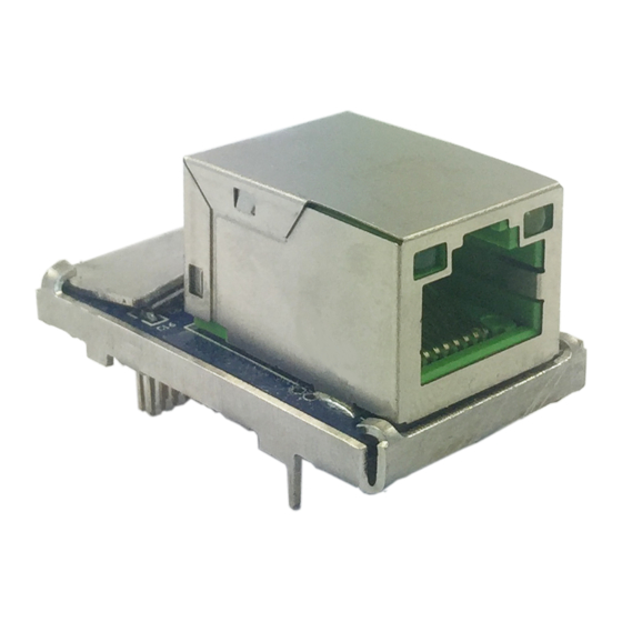
GS11-EI Embedded EtherNet/IP Module User Manual 2. Hardware 2.1 Appearance Network connecting indicator Network activity indicator 2.2 Indicators Indicator Status Description No network connection Green Always on Have network connection No network data transmitting or receiving Yellow Blinking Have network data transmitting or receiving 2.3 Interface... -
Page 7: Host Interface
Pin 7 BID+ Bi-directional Data+ Pin 8 BID- Bi-directional Data- 2.3.2 Host Interface GS11-EI has a 20-pin socket connector (needle-type), including power, UART and GPIO. The pin position and definition are as follows: Pins Signals Description 1 ~ 6 Reserved... -
Page 8: Uart Baud Rate
GS11-EI Embedded EtherNet/IP Module User Manual If this pin is pull down to low voltage before starting the module (by using a 1K pull-down resistor), the module will start with default IP address (192.168.0.11), and this mode is only used to update the firmware. -
Page 9: Reset Signal
2.5 Reset Signal GS11-EI RESET (Pin 14) is hardware reset signal input. When the RESET pin is pulled down to GND or low to 2.88V lasting for 1 millisecond, the module will be forced to reset, and the host must wait for 250 milliseconds (typical value, after reset the module), and then the host must check the PIN10 (/RUN) and PIN20 (/ DATAEXCH). -
Page 10: Communication Protocol
3. Communication Protocol 3.1 Description GS11-EI acts as an EtherNet/IP server at the Ethernet side, serial port use user-defind protocol. The EtherNet / IP communication and serial communication are completely independent, through the internal input and output data buffer of GS11-EI to realize data exchange, according to the GS11-EI serial communication protocol, the user board can complete the input and output data exchange. -
Page 11: Real-Time Monitoring Ip Function
User Manual 3.3 Real-time monitoring IP function If the GS11-EI is set to DHCP, then the module will monitor its IP when it is running. If IP changed, it will pull up /DataExch pin to logic 1.Then two cases: Using configuration software setting IP address mode: The module will obtain an IP again. User needs to... -
Page 12: Initialize Communication
17 which includes all following bytes except the check sum byte and the length byte , high-byte first The default value is 0; when user set GS11-EI via UART that use DHCP to assign IP address, the value of this byte is 1 * IP Configuration Mode, 0: Static Configuration;... -
Page 13: User-Defind Protocol
For example: GS11-EI sends message to user board: 0C C0 A8 00 BB FF FF FF 00 C0 A8 00 01 95. The 0x0C is the header and means there are 12 bytes behind, and followed by is a 4 bytes of IP address (192.168.0.187), 4 bytes of subnet mask (255.255.255.0), 4 bytes The default gateway (192.168.0.1), the last byte... - Page 14 GS11-EI Embedded EtherNet/IP Module User Manual Request message (user board -> module) Byte Description message length includes all following bytes except the check sum byte , high-byte first Input data, high-byte first … Check sum, byte 0+byte 1+…+byte n Response message of user-defind protocol (module -> user board)
-
Page 15: Dimension
GS11-EI Embedded EtherNet/IP Module User Manual 4. Dimension Unit: [mm] Front:... - Page 16 GS11-EI Embedded EtherNet/IP Module User Manual Side: PCB dimension:...
-
Page 17: Development Board
GS11-EI Embedded EtherNet/IP Module User Manual 5. Development Board 5.1 Appearance 5.2 Function 5.2.1 RS232 Interface RS232 interface is DB9 pin-connector, the description show as follow: Signal Description Connect with pin TX of RS232 of PC Connect with pin RX of RS232 of PC... -
Page 18: Baudrate Setting Switch
GS11-EI Embedded EtherNet/IP Module User Manual Development PC 机 board RS232 interface RS232 interface 5.2.2 Baudrate Setting Switch The 4-bit DIP switch on the development board is used to set the serial (UART) baud rate and default IP address locking(For firmware update):... -
Page 19: Reset Key
Subnet mask:255.255.255.0 Default gateway:192.168.0.1 5.2.3 Reset Key The key on the development board is the reset key, which is used to manual reset GS11-EI. 5.2.4 LED There are six indicators on the development board, and the description is as follows:... -
Page 20: Configuration Software
RAM: min. 256 M Byte, recommended 512 M Byte · Keyboard and Mouse 6.1 SST-EIP-CFG Introduction SST-EIP-CFG is a product based on Windows platform, and is used to configure parameters of GS11-EI, Double click the icon to run the SST-EIP-CFG and its main window will appear.:... -
Page 21: Search Equipment
6.2 Search Equipment Before parameters configuration of GS11-EI, you need to search the equipment. Click the "Search Equipment" button in the main window, SST-EIP-CFG will automatically list all of the GS11-EI on the network, as shown below. 6.3 IP Search When the user just wants to search a known IP address device on the network, click “IP Search”... -
Page 22: Advanced Configuration
GS11-EI Embedded EtherNet/IP Module User Manual 6.4 Advanced Configuration Note: The Advanced configuration is used to set your product-related parameters, here you need to set the administrator password to prevent other users modify the Advanced parameters through the SST-EIP-CFG. Select one device in the main window, Click “Advanced Configuration” button. - Page 23 Ethernet Parameters:(as shown above) Name——Enter a name to identify the GS11-EI module, it can also be the name of user's final product; IP Configuration Mode——Set the device's IP address configuration mode, Static or DHCP;...
- Page 24 It is used to set the GS11-EI to send a packet that reports its own current IP address, subnet mask, and default gateway to a port of the specified IP address device, which is sent as UDP. You can enable this function by...
- Page 25 GS11-EI Embedded EtherNet/IP Module User Manual clicking on the "IP Address Report" button in the main interface of SST-EIP-CFG. Click Start and the SST-EIP-CFG will list all of the messages sent by the devices on the network. After this function is enabled, you need to set the IP address and port number of the remote device, and the...
- Page 26 UART. The user board sets parameters such as the IP address by sending an initialization request packet; see section 3.3. Ethernet/IP connection parameters: The GS11-EI supports 3 sets of connection parameters. Each set of parameters has input and output. The number of input and output bytes can be any...
-
Page 27: User Parameter Configuration
GS11-EI Embedded EtherNet/IP Module User Manual 6.5 User Parameter Configuration Note: The user parameter configuration is the parameters set by your user, such as the IP address parameters (If the IP address obtain method in Advanced Parameters choose “Setting the IP address via software SST-EIP-CFG”, see section 6.6) - Page 28 In this interface, users can configure: Ethernet, Password, IP Address Report. The following describes the above interface in turn. Ethernet Parameters:(as shown above) Name——Enter a name to identify the GS11-EI module, it can also be the name of user's final product;...
- Page 29 It is used to set the GS11-EI to send a packet that reports its own current IP address, subnet mask, and default gateway to a port of the specified IP address device, which is sent as UDP. You can enable this function by clicking on the "IP Address Report"...
- Page 30 GS11-EI Embedded EtherNet/IP Module User Manual After this function is enabled, you need to set the IP address and port number of the remote device, and the auto report period, as shown below:...
-
Page 31: Configuration Software(Eemtest)
GS11-EI. The software function is to test the data transceiver of GS11-EI and GS11-MT. The manual introduces the method of testing GS11-EI. You can obtain the method of testing GS11-MT in GS11-MT user manual. You need to use the software with GS11-EI development board. We are very sorry that the testing software may have bugs! Double click the icon to enter the main Window: 7.2 User Interface... -
Page 32: Establish/Disconnect Connection
Work mode: The first combo box in Parameters Configuration session is to set work mode, the current version of the GS11-EI only supports user-defind protocol operating mode. Setting the IP address via host interface (UART): when you choose it, “IP configuration mode”, “IP ... - Page 33 GS11-EI Embedded EtherNet/IP Module User Manual “Port” is the serial port being used; “Baudrate” is current serial port baud rate set by DIP switches. After configuring parameters, click “Initialize” to establish the connection and initialize hardware configuration. When choosing “Setting the IP address via host interface (UART)”, click “Initialize” to send initial messages and enter the running status.
- Page 34 GS11-EI Embedded EtherNet/IP Module User Manual If the connection is failed, there will pop up an alert dialog, and the options in the Parameters Configuration section will not be grayed.
-
Page 35: Receive/Transmit Data
GS11-EI Embedded EtherNet/IP Module User Manual After establishing connection successfully, you can click "Stop" to disconnect the connection. The gray options will be usable after disconnecting, “Stop” button will change to “Run”, and “Transmit” button will change to be unusable. - Page 36 GS11-EI Embedded EtherNet/IP Module User Manual Cyclical: If you want to transmit data cyclically, you need to check “Cyclical”, and click “Transmit” button; if you want to stop transmitting data cyclically, you only need to uncheck “Cyclical”. Note: The format of the data transmitted must be correct, or you can not transmit them.
-
Page 37: Precautions Of Operation And Maintenance
GS11-EI Embedded EtherNet/IP Module User Manual 8. Precautions of Operation and Maintenance The module must be protected from heavy pressure to prevent the panel damage; The module must be protected from impact and may damage the internal components. -
Page 38: Appendix: How To Read And Write I/O Data
GS11-EI Embedded EtherNet/IP Module User Manual Appendix: How to Read and Write I/O Data There are 2 ways to read and write I/O data. Use I/O Method to Read and Write Data The following uses RSLogix 5000 as an example to explain how to use I/O method to read and write I/O data. - Page 39 GS11-EI Embedded EtherNet/IP Module User Manual In the pop out module selection window, click on the "+" in front of "Communications", select "ETHERNET-MODULE" and click "OK" as shown below:...
- Page 40 GS11-EI Embedded EtherNet/IP Module User Manual Set the related information of GS11-EI in the pop out window, as shown below. Set the Instance and the corresponding number of bytes. This setting indicates 128-byte input, 128-byte output. Set the name of the added...
- Page 41 This setting cannot be changed after confirmation. If you need to change the data type, you can create a new module. IP Address: Set the IP address of the EtherNet IP Slave module need to be connected, it is also the GS11-EI's IP address.
- Page 42 GS11-EI Embedded EtherNet/IP Module User Manual In the figure above, GS11EI:O.Data [0]~GS11EI:O.Data [127] is the corresponding output data address of the added GS11-EI module in the master station. Click on "GS11EI: I", as shown below:...
-
Page 43: Use Msg Method To Read And Write Data
GS11-EI Embedded EtherNet/IP Module User Manual In the figure above, the 4 bytes corresponding to GS11EI:I.Data [0] is the real time frame header of EtherNet IP slave station. GS11EI: I.Data[1]~GS11EI: I.Data[127] is the corresponding input data address of the added GS11EI module in the master station. - Page 44 GS11-EI Embedded EtherNet/IP Module User Manual In the new window that pops out, you need to make the following settings: Message Type: CIP Generic Service Type: select “Get Attribute Single”, at this point, the corresponding Service Code becomes to "e (Hex)"...
- Page 45 EtherNet IP master resides, and the connected EtherNet IP address. After the path is set up, click "Apply" and "Confirm". As shown below. In this example, the name of EtherNet IP master is "Master", the EtherNet IP master station is in the slot number "2", and the connected EtherNet IP slave (GS11-EI) has the IP address "192.168.0.10".
- Page 46 GS11-EI Embedded EtherNet/IP Module User Manual Add a "MSG" instruction to "MainRoutine" under "MainProgram" and select "ReadTag" as "Message Control", as shown below. PLC read data instruction This is a simple instruction that can send a read request. In a normal program, some logical commands need...
- Page 47 GS11-EI Embedded EtherNet/IP Module User Manual to be added to trigger this instruction. For details on this instruction, refer to RSLogix5000. Download the program to the PLC and put the PLC in the "Online" state. Click on "Control Tags" and select "Monitor Tags" to expand "ReadData", as shown below. The data stored at the starting address ReadData[0] is the data of the Modbus slave station read by the PLC via the gateway GS11-EI.
- Page 48 Go to the "Monitor Tags" page. WriteData[0] starts to input some data in the "WriteData" tab. The data will be output by the PLC to the GS11-EI and output to the Modbus slave device via the configured Modbus write command.
- Page 49 GS11-EI Embedded EtherNet/IP Module User Manual In the new window that pops out, you need to make the following settings: Message Type: CIP Generic Service Type: select “Get Attribute Single”, at this point, the corresponding Service Code becomes to "10(Hex)"...
- Page 50 "Confirm". As shown below. In this example, the EtherNet IP master station name is "Master", the EtherNet IP master station is in the slot number "2", and the connected EtherNet IP slave (GS11-EI) has the IP address "192.168.0.10". The IP address of...
- Page 51 PLC read data instruction PLC write data instruction Download the PLC program to the PLC and put the PLC in the "Online" state. The data in "WriteData" will be output to the Modbus slave station via the GS11-EI (EtherNet IP Slave station).
Need help?
Do you have a question about the GS11-EI and is the answer not in the manual?
Questions and answers