Table of Contents
Advertisement
Advertisement
Table of Contents

Summary of Contents for Mindray BeneLink
- Page 1 BeneLink Module Operator’s Manual...
- Page 3 © Copyright 2018 Shenzhen Mindray Bio-Medical Electronics Co., Ltd. All rights reserved. Release time: December 2018 Revision 3.0. WARNING Federal Law (USA) restricts this device to sale by or on the order of a physician or other practitioner licensed by U.S. state law to use or order the use of this device.
- Page 4 Mindray) owns the intellectual property rights to this Mindray product and this manual. This manual may refer to information protected by copyrights or patents and does not convey any license under the patent rights or copyright of Mindray, or of others.
- Page 5 Manufacturer’s Responsibility Contents of this manual are subject to changes without prior notice. Mindray is responsible for the effects on safety, reliability and performance of this product, only if: all installation operations, expansions, changes, modifications and repairs of this product are conducted by Mindray authorized personnel;...
- Page 6 Service Mindray maintains a network of service representatives and factory-trained distributors. Prior to requesting service, perform a complete operational check of the instrument to verify proper control settings. If operational problems continue to exist, contact Mindray service. In North America contact the Service Department at (800) 288-2121, ext: 8116 for Technical Support or (201) 995-8000 for assistance in determining the nearest field service location.
- Page 7 Company Contact Manufacturer: Shenzhen Mindray Bio-Medical Electronics Co., Ltd. Mindray Building, Keji 12th Road South, High-tech industrial Address: park, Nanshan,Shenzhen 518057,P.R.China Website: www.mindray.com E-mail Address: service@mindray.com Tel: +86 755 81888998 Fax: +86 755 26582680 Distributor: Mindray DS USA, Inc. Address:...
- Page 8 This manual is for biomedical engineers, authorized technicians or service representatives responsible for troubleshooting, repairing and maintaining the monitors Contact your local Mindray Service Organization for information on product courses which address service and support for this product. BeneLink Module Operator’s Manual...
-
Page 9: Table Of Contents
2.7 Accessories ................ 3-1 3 Integrating the Anesthesia Machine ........................3-1 3.1 Draeger Apollo ................... 3-1 3.1.1 Output Signals—Parameters ................... 3-4 3.1.2 Output Signals—Alarms ... 3-8 3.1.3 Output Signals – Waveforms (For BeneVision N Series Monitors only) BeneLink Module Operator’s Manual... - Page 10 ..3-46 3.8.3 Output Signals - Waveforms (For BeneVision N Series Monitors only) ..................4-1 4 Integrating the Ventilator .........4-1 4.1 Carefusion Avea (For BeneVision N Series Patient Monitor Only) ..................4-1 4.1.1 Output Signals - Parameters BeneLink Module Operator’s Manual...
- Page 11 4.9 GE Carescape R860 .................4-34 4.9.1 Output Signals—Parameters 4-37 4.9.2 Output Signals – WaveForms (For BeneVision N Series Patient Monitor Only) 4.9.3 Output Signals – Respiratory Loops (For BeneVision N Series Patient ........................4-37 Monitor Only) ..................4-37 4.9.4 Output Signals—Alarms BeneLink Module Operator’s Manual...
- Page 12 4.16.4 Output Signals—Respiratory Loops (For BeneVision N Series Monitor Only) ............................... 4-75 ........................4-76 4.17 Newport E360 ................4-76 4.17.1 Output Signals – Parameters ..................4-77 4.17.2 Output Signals – Alarms ............... 4-80 4.18 Philips Respironics V60 (SNDA Protocol) BeneLink Module Operator’s Manual...
- Page 13 6 Integrating Infusion System (For BeneVision N Series Monitors only) .................... 6-1 6.1 B.Braun Perfusor Space Pumps ..................6-1 6.1.1 Output Signals – Parameters ..............6-1 6.2 Fresenius Agilia Injectomat Infusion Pumps ..................6-1 6.2.1 Output Signals - Parameters BeneLink Module Operator’s Manual...
- Page 14 9.3.5 Setting the Serial Ports of Other External Devices ..............9-10 9.4 Troubleshooting Device Integration Failures ................9-11 9.5 BeneLink Installation and Test Report ....10-1 10 Alarm ID of External Devices (For BeneVision N Series Monitors only) BeneLink Module Operator’s Manual...
- Page 15 10.2 Alarm IDs of Ventilators ................10-8 10.3 Alarm IDs of the Pulse CO-Oximeter ............... 10-13 10.4 Alarm IDs of tcGas monitoring devices ................10-13 10.5 Alarm IDs of NMT monitoring device ..................10-14 10.6 Alarm IDs of Infusion Systems BeneLink Module Operator’s Manual...
- Page 16 FOR YOUR NOTES...
-
Page 17: Safety
Indicates a potential hazard or unsafe practice that, if not avoided, could result in minor personal injury or product/property damage. NOTE Provides application tips or other useful information to ensure that you get the most from your product. BeneLink Module Operator’s Manual... -
Page 18: Warnings
1.2 Warnings WARNING The BeneLink module receives parameter, alarm, and waveform data from external devices but will not modify this data. For example, the external device may display "---", but send "0" to the patient monitor. There can be differences between the alarm priorities displayed on ... -
Page 19: Notes
1.4 Notes NOTE Devices of the same category cannot be connected to the BeneLink module simultaneously. The BeneVision N Series monitor supports up to two BeneLink modules, while the Passport M Series supports only one. The alarm messages from external devices are derived from the open ... - Page 20 FOR YOUR NOTES BeneLink Module Operator’s Manual...
-
Page 21: Interfacing With External Devices
Interfacing with External Devices 2.1 BeneLink Introduction BeneLink module is intended for connecting external devices, such as ventilators and anesthesia machines, to the BeneVision N Series monitors or Passport 12m/17m monitors. It allows information (patient data, alarms, etc.) from external devices to be displayed, saved, recorded, or printed through the monitor. -
Page 22: Data Transmission
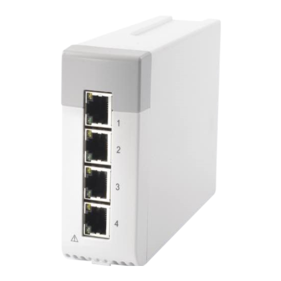
2.3 Data transmission The Benelink module is connected with external devices via the serial ports (physical interfaces are RJ45 connectors). You can simultaneously connect up to four external devices via one BeneLink module. Parameters, alarm data from the external devices can be output. -
Page 23: Supported Ventilators
Type B Carescape R860 4F52B0AE Type B Engström(Carestation) 4F45B0BB Type B Hamilton C1/C2/C3/T1 (C1 and T1 are 3270CD90 Type B for BeneVision N Series only) G5 (Block Protocol) 3542CABE Type B G5 (Polling Protocol) 3550CAB0 Type B BeneLink Module Operator’s Manual... - Page 24 Puritan PB840 5042AFBE None needed Bennett (SNDF protocol) PB840 5031AFCF None needed (SNDA protocol) PB980 5042AFBE Type C (SNDF protocol) PB980 5031AFCF Type C (SNDA protocol) ResMed VSIII (for Passport M series 5653A9AD Type C only) BeneLink Module Operator’s Manual...
-
Page 25: Supported Tcgas Monitoring Devices
B.Braun Perfusor Space 4250BDB0 Type F Fresenius Agilia Injectomat 4650b9b0 Type G Agilia Injectomat MC 4650b9b0 Type G Agilia Injectomat TIVA 4650b9b0 Type G Agilia Volumat 4650b9b0 Type G Agilia Volumat MC 4650b9b0 Type G BeneLink Module Operator’s Manual... -
Page 26: Supported Other Devices
The ID adapter can be configured to support the DIAP protocol. When the ID adapter is connected to the BeneLink module, the third party device can obtain the measurement numerics and alarm limit settings of the current patient through the DIAP protocol. -
Page 27: Configuring The Id Adapter
Maintenance>>] → input the factory maintenance password → [Update ID module]. Set [Benelink Module Port] and [ID]. The setting of [Benelink Module Port] shall be consistent with the port the RJ45 connecting cable is connected to. You must connect the RJ45 connecting cable to the selected port when ... -
Page 28: Connecting External Devices
2.6 Connecting External Devices The external devices are connected with the BeneLink module through an ID adapter, which supports only its matching device. Please refer to the following procedure to connect an external device: BeneLink module Label RJ45 connecting cable... - Page 29 Switch on the external device. After the external device is connected to the monitor, the indicators on both the ID adapter and the BeneLink module illuminate to show that the monitor is successfully communicating with the external device. BeneLink Module Operator’s Manual...
-
Page 30: Accessories
Serial port adapting cable, Type F, 9-pin (male) to 9-pin 009-008485-00 (male), custom pin out Serial port adapting cable, Type G, 9-pin (male) to 8-pin 009-008624-00 (male) 047-004857-00 ID adapter label 047-004859-00 Network line label 009-001770-00 RJ45 connecting cable 2-10 BeneLink Module Operator’s Manual... -
Page 31: Integrating The Anesthesia Machine
Positive end-expiratory pressure Ppeak Peak pressure Pplat Plateau pressure Pmean Mean pressure Inspired tidal volume Minute volume fspn Spontaneous respiratory rate Compl Compliance RRCO2 Respiratory rate of CO EtCO2 End-tidal carbon dioxide FiCO2 Fraction of inspired carbon dioxide BeneLink Module Operator’s Manual... - Page 32 2nd Insp. Agent EtAA 2nd 2nd Exp. Agent Insp. MAC Inspired minimum alveolar concentration Exp. MAC Expired minimum alveolar concentration HALLev Anesthetic agent consupmtion ENFLev Anesthetic agent consupmtion ISOLev Anesthetic agent consupmtion DESLev Anesthetic agent consupmtion BeneLink Module Operator’s Manual...
- Page 33 Time for the pressure to rise to target Tslope pressure Tinsp Time of inspiration Pinsp Pressure control level of inspiration Psupp Pressure support level Pmax Maximal breathing pressure F-Trigger Inspiratory trigger level (flow trigger) BeneLink Module Operator’s Manual...
-
Page 34: Output Signals-Alarms
No Pulse PR Low SpO2 Low FiO2 High VTe Low MV High MV Low PEEP High EtCO2 High EtCO2 Low Medium FiCO2 High O High EtHAL High FiHal High FiHal Low EtENF High FiENF High FiENF Low BeneLink Module Operator’s Manual... - Page 35 If the monitor shows the alarm [High Technical alarms], the external device has one or more of the High following alarms: VENT ERR High INT.TMP.HIGH Technical O2CYL.DISCON Alarm CHK N O CYL NO N O DELIV NO AIR DELIV FG-OVER? BeneLink Module Operator’s Manual...
- Page 36 MIXED AGENT Module CO2/AGT ERR abnormal O ERR AGT ERR 2ND AGENT If the monitor shows the alarm [CO2 Module abnormal], the external device may have the Module following alarms: abnormal CO2 LINE BLK BeneLink Module Operator’s Manual...
- Page 37 O SENS? NO AIR NO O2 SUPPLY Module If the monitor shows the alarm [SpO abnormal], the external device has one or more of SpO2 the following alarms: Module SPO2SEN DISC abnormal SPO2 ALRM OF SPO2 ERR BeneLink Module Operator’s Manual...
-
Page 38: Output Signals - Waveforms (For Benevision N Series Monitors Only)
O2 CYL .SENS? AIR CYL? PRESS RELIEF INSP VOL ERR 3.1.3 Output Signals – Waveforms (For BeneVision N Series Monitors only) The following waveforms from the external device can be output to the monitor: Flow BeneLink Module Operator’s Manual... -
Page 39: Draeger Fabius Gs /Fabius Tiro
FiIso Inspired anesthetic agent FiHal Inspired anesthetic agent EtEnf End-tidal anesthetic agent EtDes End-tidal anesthetic agent EtIso End-tidal anesthetic agent EtSev End-tidal anesthetic agent EtHal End-tidal anesthetic agent FiAA Inspired anesthetic agent EtAA End-tidal anesthetic agent BeneLink Module Operator’s Manual... - Page 40 Percentage of inspiratory plateau time in TIP:TI inspiratory time Tinsp Time of inspiration Pinsp Pressure control level of inspiration Psupp Pressure support level Pmax Maximal breathing pressure Inspiratory trigger F-Trigger level (flow trigger) Insp Flow Inspiration flow 3-10 BeneLink Module Operator’s Manual...
-
Page 41: Output Signals - Alarms
VENT ERR. Check Expiration-Valve Check Fresh Gas Supply Medium Medium If the monitor shows the alarm [Medium Technical alarms], the external device has one or more of the Technical alarms following alarms: BeneLink Module Operator’s Manual 3-11... - Page 42 SPEAKER FAIL POWER FAIL CAL % O2 ? Technical % O2 ERR alarms TIME LIMITED RS232COM ERR PORT 1 ERROR PORT 2 ERROR THRESHOLD LO 3-12 BeneLink Module Operator’s Manual...
-
Page 43: Draeger Perseus A500
FiIso Inspired anesthetic agent FiDes Inspired anesthetic agent FiEnf Inspired anesthetic agent FiSev Inspired anesthetic agent FiHal Inspired anesthetic agent End-tidal anesthetic agent EtEnf End-tidal anesthetic agent EtDes End-tidal anesthetic agent EtIso End-tidal anesthetic agent BeneLink Module Operator’s Manual 3-13... - Page 44 FiO2 EtO2 End-tidal O Inspired tidal volume FiCO2% Fraction of inspired carbon dioxide EtCO2% End-tidal carbon dioxide Difference between inspiratory and ΔO2 % expiratory O EtO2% End-tidal O Fractional concentration of O in inspired FiO2% 3-14 BeneLink Module Operator’s Manual...
-
Page 45: Output Signals-Alarms
3.3.2 Output Signals—Alarms Monitor output: alarms from Draeger Perseus A500 anesthesia machine Priority Label Physiological alarms Apnea FiO2 Low CO2 Apnea High Pressure Apnea Paw High Paw Low CONT PRES FiHal High Medium FiEnf High BeneLink Module Operator’s Manual 3-15... - Page 46 Medium FiHal Low FiEnf Low FiIso Low FiDes Low FiSev Low FiCO2 High MV High EXP-VALVE? PEEP High VTe High MAC Low O High Technical alarms O2 Supply Failure High NO Fresh Gas VENT DISC 3-16 BeneLink Module Operator’s Manual...
- Page 47 BATTERY LOW % O2 ERR Medium O SUPPLY ? Medium Technical POWER FAIL Alarm SAFETY O2 ON FG LIMITED LOSS OF DATA SET.CANCELED FG HIGH FG ACTIVE BeneLink Module Operator’s Manual 3-17...
- Page 48 RS232COM ERR PRESS ERR WATER TRAP ? Technical VENT TEMP HI Alarm VOL ERR FAN ERR O PRESS HI O2 CYL. ? VOLAT SUPPLY CO2-LINE ? PWR SPLY ERR 3-18 BeneLink Module Operator’s Manual...
-
Page 49: Output Signals - Waveforms (For Benevision N Series Monitors Only)
PRESS RELIEF ABSORB. OLD? ID-FUNC-INOP HOSE OLD? 3.3.3 Output Signals - Waveforms (For BeneVision N Series Monitors only) The following waveforms from the external device can be output to the monitor: Flow BeneLink Module Operator’s Manual 3-19... -
Page 50: Ge Aespire 7900&7100/Aestiva 7900&7100
Tidal volume Breath rate Percentage of inspiratory plateau time in inspiratory time Percentage of inspiratory plateau time in TIP:TI inspiratory time PEEP Positive end-expiratory pressure Plimit Pressure limit level Pinsp Pressure control level of inspiration 3-20 BeneLink Module Operator’s Manual... -
Page 51: Output Signals - Alarms
If the monitor shows the alarm [High Technical alarms], the external device has one or more of the following alarms: High Pinspired Not Achieved High Technical Inspiration Stopped alarms +15V SIB Out-of-Range +15V Manifold Out-of-Range Display Voltage Out-of-Range Vaux_ref Out-of-Range BeneLink Module Operator’s Manual 3-21... - Page 52 Medium Manifold Pressure Sensor Failure Technical High Pressure Limit Reached (min sys) Medium alarms Inspiratory Reverse Flow Expiratory Reverse Flow Check Flow Sensors Flow Valve Failure Gas Inlet Valve Failure Bootup Gas Inlet Valve Failure 3-22 BeneLink Module Operator’s Manual...
- Page 53 Bellows Empty alarms +Vanalog Failure -Vanalog Failure Flow Sensor Cal Data Corrupt Low Battery Low Battery (shutdown) Battery Voltage Out Of Range Battery Current Out Of Range Circuit Auxiliary Auxiliary Breathing Circuit Service Calibrations Due BeneLink Module Operator’s Manual 3-23...
-
Page 54: Output Signals - Waveforms (For Benevision N Series Monitors Only)
Expiratory minute volume Total respiratory rate ftot Oxygen concentration Ppeak Peak pressure Pplat Plateau pressure Pmean Mean pressure Pmin Minimum airway pressure Spontaneous breathed minute volume MVspn Spontaneous respiratory rate fspn Inspired tidal volume Inspiratory minute volume 3-24 BeneLink Module Operator’s Manual... - Page 55 Percentage of inspiratory plateau time in TIP:TI inspiratory time PEEP Positive end-expiratory pressure Plimit Pressure limit level Pinsp Pressure control level of inspiration Psupp Pressure support level Inspiratory trigger level (flow trigger) F-Trigger Time of inspiration Tinsp BeneLink Module Operator’s Manual 3-25...
-
Page 56: Output Signals - Alarms
Patient Circuit Leak Medium Medium Technical alarms Battery in Use Low Technical alarms 3.5.3 Output Signals – Waveforms The following waveforms from the external device can be output to the monitor: Flow Volume 3-26 BeneLink Module Operator’s Manual... -
Page 57: Output Signals - Respiratory Loops
Expiratory minute volume ftot Total respiratory rate Oxygen concentration Ppeak Peak pressure Pplat Plateau pressure Pmean Mean pressure Pmin Minimum airway pressure MVspn Spontaneous breathed minute volume fspn Spontaneous respiratory rate Inspired tidal volume Inspiratory mimute volume BeneLink Module Operator’s Manual 3-27... - Page 58 Percentage of inspiratory plateau time in TIP:TI inspiratory time PEEP Positive end-expiratory pressure Plimit Pressure limit level Pinsp Pressure control level of inspiration Psupp Pressure support level Inspiratory trigger F-Trigger level (flow trigger) Tinsp Time of inspiration 3-28 BeneLink Module Operator’s Manual...
-
Page 59: Output Signals - Alarms
If the monitor shows the alarm [Medium Technical alarms], the external device has one or more of the Medium following alarms: Medium Technical High Circuit O2 alarms Low Circuit O2 No O2 Cell Sensor No Pressure Cntrl/PEEP BeneLink Module Operator’s Manual 3-29... - Page 60 Replace O2 Cell O2 Cell Calibration Error Vt Not Achieved Technical No Inspiratory Flow Sensor alarms No Expiratory Flow Sensor Dry or Replace Sensors System Leak? Unable to drive bellows Memory (EEPROM) Failure 3-30 BeneLink Module Operator’s Manual...
-
Page 61: Output Signals - Waveforms (For Benevision N Series Monitors Only)
Monitor output: parameters from MAQUET FLOW-i anesthesia machine Label Description Trend, record, print Monitoring Parameters PEEP Positive end-expiratory pressure Ppeak Peak pressure Pplat Plateau pressure Pmean Mean pressure Inspired tidal volume Expiratory minute volume Inspiratory mimute volume BeneLink Module Operator’s Manual 3-31... - Page 62 Duty cycle or ratio of inspiration time Ti/Ttot to total breathing cycle time (only during spontaneous breathing) Fractional concentration of O in inspired FiO2% EtO2% End-tidal O FiCO2% Fraction of inspired carbon dioxide EtCO2% End-tidal carbon dioxide Expiratory tidal volume 3-32 BeneLink Module Operator’s Manual...
- Page 63 P-Trigger level(pressure trigger) Inspiratory trigger F-Trigger level (flow trigger) Insp Flow Inspiratory flow Fresh gas flow PEEP Positive end-expiratory pressure Rise Time% rise time% Tpause% Pause Time Tinsp% Time of inspiration Tpause s Pause Time BeneLink Module Operator’s Manual 3-33...
-
Page 64: Output Signals - Alarms
FiCO2 High O High Medium EtIso High EtIso Low FiIso High FiIso Low EtSev High EtSev Low FiSev High FiSev Low EtDes High EtDes Low FiDes High FiDes Low EtO2 High EtO2 Low FiO2 High 3-34 BeneLink Module Operator’s Manual... - Page 65 Medium Medium Gas Analyzer water trap Technical Gas Analyzer water trap missing alarms internal communication failure High continuous APL Pressure alarm Leakage alarm Battery in Use BeneLink Module Operator’s Manual 3-35...
-
Page 66: Mindray
NOTE Only the Benevision N series monitor supports integration with the Mindray A4 Anesthesia machine. 3.8.1 Output Signals – Parameters Monitor output: parameters from Mindray A7/A5/A4/A3 anesthesia machine Label Description Trend, record, print Monitoring Parameters Inspiratory time: Expiratory time ratio... - Page 67 Monitor output: parameters from Mindray A7/A5/A4/A3 anesthesia machine Label Description Trend, record, print EtEnf End-tidal anesthetic agent EtIso End-tidal anesthetic agent EtHal End-tidal anesthetic agent FiDes Inspired anesthetic agent FiSev Inspired anesthetic agent FiEnf Inspired anesthetic agent FiIso Inspired anesthetic agent...
- Page 68 Monitor output: parameters from Mindray A7/A5/A4/A3 anesthesia machine Label Description Trend, record, print Difference between the inspiratory and MV Leak expiratory minute volume Setting Parameters Inspiratory trigger F-Trigger level (flow trigger) Tidal volume Breath rate PEEP Positive end-expiratory pressure Plimit...
-
Page 69: Output Signals - Alarms
3.8.2 Output Signals – Alarms Monitor output: alarms from Mindray A7/A5/A4/A3 anesthesia machine Priority Label Physiological alarms Apnea Volume Apnea>2min Paw High Paw Low High FiO2 High FiO2 Low CO2 Apnea MV High MV Low BIS High BIS Low EtCO2 High... - Page 70 Monitor output: alarms from Mindray A7/A5/A4/A3 anesthesia machine Priority Label FiEnf High EtIso Low EtIso High FiIso Low FiIso High EtSev Low EtSev High FiSev Low Medium FiSev High EtDes Low EtDes High FiDes Low FiDes High VTe High VTe Low...
- Page 71 Monitor output: alarms from Mindray A7/A5/A4/A3 anesthesia machine Priority Label alarms Check Flow Sensors O2-N O Ratio Error Flowmeter Comm Stop Aux Control Module Comm Stop Power System Comm Stop System going DOWN,Battery depleted! Power Board High Temp Breathing System Not Mounted Flowmeter Cal.
- Page 72 Monitor output: alarms from Mindray A7/A5/A4/A3 anesthesia machine Priority Label If the monitor shows the alarm [Medium Technical alarms], the external device has one or more of the following alarms: PEEP Valve Failure Insp Valve Failure ACGO 3-way Valve Failure...
- Page 73 Monitor output: alarms from Mindray A7/A5/A4/A3 anesthesia machine Priority Label If the monitor shows the alarm [AG Module Abnormal], the external device has one or more of the following alarms: AG Hardware Error O2 Sensor Error External AG Self Test Error...
- Page 74 Monitor output: alarms from Mindray A7/A5/A4/A3 anesthesia machine Priority Label BISx Disconnected BIS Comm Error BIS Over Range BIS High Imped. BIS Sensor Off BIS DSC Error BIS DSC Malf BIS Module Medium BIS No Cable abnormal BIS No Sensor BIS Wrong Sensor Type BIS SQI<50%...
- Page 75 Monitor output: alarms from Mindray A7/A5/A4/A3 anesthesia machine Priority Label Internal Air Flow Failure Heating Module Failure Automatic Ventilation Disabled BIS Electrode Unconnected BIS Electrode 1/2/3/4 Lead Off BIS Electrode 1/2/3/4 High Imped. N2O Flow Too High O2 Flow Too High...
-
Page 76: Output Signals - Waveforms (For Benevision N Series Monitors Only)
3.8.3 Output Signals - Waveforms (For BeneVision N Series Monitors only) The following waveforms from the external device can be output to the monitor: Flow Volume 3-46 BeneLink Module Operator’s Manual... -
Page 77: Integrating The Ventilator
Oxygen concentration Inspiratory time: Expiratory time ratio Leak Comp Leak compensation PEEP Positive end-expiratory pressure Exp.Flow Expiratory flow Insp.Flow Inspiratory flow Pmean Mean pressure Oxygen supply pressure Ppeak Peak pressure Pplat Plateau pressure ftot Total breath rate BeneLink Module Operator’s Manual... - Page 78 Expiratory minute volume Tinsp Time of inspiration Texp Expiratory time Inspiratory resistance RSBI Rapid shallow breathing index Pair Air supply pressure P0.1 100 ms occlusion pressure PEEPi Intrinsic positive end-expiratory pressure PEEPe Extrinsic positive end-expiratory pressure Expiratory resistance BeneLink Module Operator’s Manual...
- Page 79 Positive end-expiratory pressure Psupp Pressure support level Breath rate Trise Rise time Tinsp Time of inspiration Tlow Time for the lower pressure level F-Trigger Inspiratory trigger level (flow trigger) P-Trigger Inspiratory trigger level (pressure trigger) Tidal volume BeneLink Module Operator’s Manual...
-
Page 80: Output Signals - Alarms
RR High Medium VTe Low VTe High Technical alarms If the monitor shows the alarm [High Technical alarms], the external device may High Technical have the following alarms: alarms High Vent Inop Loss of Gas Circuit Disconnect BeneLink Module Operator’s Manual... - Page 81 Technical alarms Invalid Gas ID Fan Failure Battery in Use If the monitor shows the alarm [Low Technical alarms], the external device may have the following alarms: Low Technical Insp Time Limit alarms I:E Limit Volume Limit BeneLink Module Operator’s Manual...
-
Page 82: Output Signals - Waveforms
Spontaneous breathed minute volume Expiratory minute volume ftot Total breath rate fspn Spontaneous respiratory rate Inspiratory time:Expiratory time ratio Fractional concentration of O in inspired FiO2% Fractional concentration of O in inspired FiO2 Texp Expiratory time Oxygen supply pressure BeneLink Module Operator’s Manual... - Page 83 Lower pressure level Thigh Time for the upper pressure level Tlow Time for the lower pressure level Exp% Inspiration termination level Peak Flow Peak flow Ti max Maximum inspiration time Oxygen concentration Tpause Pressure control level of inspiration BeneLink Module Operator’s Manual...
-
Page 84: Output Signals - Alarms
VENT INOP H/W FAULT If the monitor shows the alarm [Medium Technical alarms], the external device has one or more of the Medium following alarms: Medium Technical CHECK EVENTS alarms LOW CLOCK BATTERY CO2 COMMS ERROR BeneLink Module Operator’s Manual... - Page 85 O2 INLET HIGH MED BATTERY XDCR FAULT Battery in Use If the monitor shows the alarm [Low Technical alarms], the external device has one or more of the Technical following alarms: alarms INVALID SERIAL NUMBER NO CAL DATA BeneLink Module Operator’s Manual...
-
Page 86: Draeger Babylog 8000 Plus/Babylog 8000
Fractional concentration of O2 in inspired FiO2% Setting Parameters Oxygen concentration Tinsp Time of inspiration fSIMV Frequency of SIMV PEEP/CPAP PEEP/CPAP Tapnea Apnea tidal volume Pmax Maximum airway pressure Breath rate Tidal volume Inspiratory time:Expiratory time ratio 4-10 BeneLink Module Operator’s Manual... -
Page 87: Output Signals-Technical Alarms
Positive end-expiratory pressure fmand Mandatory breathing frequency Ppeak Peak pressure VTe spn Spontaneous expiratory tidal volume MVLEAK Leakage minute volume Leak Comp Leak compensation fspn Spontaneous respiratory rate Minute volume RSBI Rapid shallow breathing index BeneLink Module Operator’s Manual 4-11... - Page 88 Intermittent PEEP Plow Lower pressure level Phigh Upper pressure level Tlow Time for the lower pressure level Thigh Time for the upper pressure level TApnea Apnea Time Psupp Pressure support level Pmax Maximal breathing pressure 4-12 BeneLink Module Operator’s Manual...
-
Page 89: Output Signals - Alarms
Inspiratory time: Expiratory time ratio 4.4.2 Output Signals – Alarms Monitor output: alarms from Draeger Babylog VN500 Ventilator Priority Label Physiological alarms Paw High Paw Low MV High High MV Low FiO2 High VT Low BeneLink Module Operator’s Manual 4-13... - Page 90 If the monitor shows the alarm [High Technical alarms], the external device may have the following alarms: CO2 NOT CAL High BATERY ERR Technical SPEAKER FAIL Alarms VENT ERR VOL CAL VOL ERR AW TEMP INOP 4-14 BeneLink Module Operator’s Manual...
- Page 91 Medium NO AIR Technical AMB_PRESS Alarms BATT LOW CHECK_EVITA NEBULIZ OF VT LIMITED Battery In use If the monitor shows the alarm [Low Technical Technical alarms], the external device may have the following Alarms alarms: BeneLink Module Operator’s Manual 4-15...
-
Page 92: Draeger Evita 2
Spontaneous breathed minute volume ftot Total respiratory rate fspn Spontaneous breathing frequency Fractional concentration of O in inspired FiO2 Rdyn Dynamic lung resistance Cdyn Dynamic compliance Pmin Minimum airway pressure Vtrap Trapped volume Inspiratory breathing gas temperature 4-16 BeneLink Module Operator’s Manual... - Page 93 Plow Lower pressure level Thigh Time for the upper pressure level Tlow Time for the lower pressure level Pmax Maximum airway pressure Flow Flow Tapnea Apnea Time ASB ramp ASB ramp PASB Assisted spontaneous breathing BeneLink Module Operator’s Manual 4-17...
-
Page 94: Output Signals - Alarms
High EXP-VALVE? /O2 Supply Pressure Low If the monitor shows the alarm [High Technical alarms], the external device has one or more of the High following alarms: Technical VOL ERR alarms PRESS ERR AW-TEMP INOP 4-18 BeneLink Module Operator’s Manual... -
Page 95: Draeger Evita2 Dura/Evita 4/Evita Xl
4.6.1 Output Signals – Parameters Monitor output: parameters from Draeger Evita2 dura/Evita 4/Evita XL Ventilator Label Description Trend, record, print Monitoring Parameters Oxygen concentration PEEP Positive end-expiratory pressure Ppeak Peak pressure Pplat Plateau pressure Pmean Mean pressure BeneLink Module Operator’s Manual 4-19... - Page 96 End-tidal carbon dioxide Dead space VCO2 production Pulse rate Arterial oxygen saturation from pulse SpO2 oximetry EtCO2% End-tidal carbon dioxide Fractional concentration of O in inspired FiO2% Setting Parameters Oxygen concentration PEEP Positive end-expiratory pressure 4-20 BeneLink Module Operator’s Manual...
- Page 97 Maximum airway pressure Tinsp Time of inspiration Flow Flow Tapnea Apnea time ASB ramp ASB ramp PASB Assisted spontaneous breathing FlowAssist Flow assist Vol.Assist Volume assist Delay time for "Airway pressure lower alarm Tdisconnect limit" BeneLink Module Operator’s Manual 4-21...
-
Page 98: Output Signals - Alarms
PEEP High ASB>4s No Pulse PR Low SpO2 Low PR High SpO2 High VTe High EtCO2 High Medium EtCO2 Low VOL INCONST RR High ASB > 1.5s PPS-TI > 1.5s ASB > Tinsp Technical alarms 4-22 BeneLink Module Operator’s Manual... - Page 99 Technical SPO2 SEN DISC alarms SPO2 ERR BATTERY ERR EVITA4 FAN ERR EVITA4 AIR PRESS HI EVITA4 HI O2 SUPPLY EVITA4 LOSS OF DATA REM.PAD-ERR PEEP V ERR CO2 NOT CAL LO O2 SUPPLY EVITA4 BeneLink Module Operator’s Manual 4-23...
-
Page 100: Output Signals - Waveforms (For Benevision N Series Monitors Only)
SYNCHRO INOP INSPHOLD END EXSPHOLD END 4.6.3 Output Signals - Waveforms (For BeneVision N Series Monitors only) The following waveforms from the external device can be output to the monitor: Flow Volume 4-24 BeneLink Module Operator’s Manual... -
Page 101: Draeger Infinity V500
Dead space Negative inspiratory force Mvleak Leakage minute volume Leak Comp Leak compensation fspn Spontaneous respiratory rate Minute volume RSBI Rapid shallow breathing index ftot Total respiratory rate EtCO2 End-tidal carbon dioxide EtCO2% End-tidal carbon dioxide BeneLink Module Operator’s Manual 4-25... - Page 102 Intermittent PEEP Δint.PEEP Plow Lower pressure level Phigh Upper pressure level Tlow Time for the lower pressure level Thigh Time for the upper pressure level Tapnea Apnea time Psupp Pressure support level Pmax Maximum airway pressure 4-26 BeneLink Module Operator’s Manual...
-
Page 103: Output Signals-Alarms
Tpause Apnea Time Exp% Inspiration termination level 4.7.2 Output Signals—Alarms Monitor output: alarms from Draeger Infinity V500 Ventilator Priority Label Physiological alarms FiO2 Low Paw High MV Low High MV High FiO2 High Paw Low BeneLink Module Operator’s Manual 4-27... - Page 104 Circuit Disconnect No O2 Pressure If the monitor shows the alarm [High Technical High alarms], the external device has one or more of the Technical following alarms: Alarm CO2 NOT CAL BATERY ERR SPEAKER FAIL 4-28 BeneLink Module Operator’s Manual...
- Page 105 Nebulization finished Alarm Ambient pressure sensor? Device check incomplete GAS FAILURE BATT LOW Battery in Use If the monitor shows the alarm [Low Technical Technical alarms], the external device has one or more of the BeneLink Module Operator’s Manual 4-29...
-
Page 106: Draeger Savina
Ppeak Peak pressure Expiratory tidal volume Inspired tidal volume Minute volume ftot Total respiratory rate MVspn Spontaneous breathed minute volume fspn Spontaneous respiratory rate Fractional concentration of O in inspired FiO2 Inspiratory breathing gas temperature 4-30 BeneLink Module Operator’s Manual... - Page 107 Tdisconnect limit" FlowACC Flow acceleration Plow Lower pressure level Phigh Upper pressure level Thigh Time for the upper pressure level Tlow Time for the lower pressure level Tinsp Time of inspiration PEEP Positive end-expiratory pressure BeneLink Module Operator’s Manual 4-31...
-
Page 108: Output Signals-Alarms
If the monitor shows the alarm [High Technical High alarms], the external device has one or more of the High following alarms: Technical High O2 supply pressure Alarm insp.O2 measurement in operation Failen to cycle 4-32 BeneLink Module Operator’s Manual... - Page 109 MICROFILTER If the monitor shows the alarm [Low Technical alarms], the external device has one or more of the following alarms: Technical insp hold aborted Alarm CO2 device failure CO2 sensor disconnected Expiration hold aborted BeneLink Module Operator’s Manual 4-33...
-
Page 110: Ge Carescape R860
FiO2 EtO2 End-tidal O Difference between inspiratory and ΔO2 expiratory O Rdyn Dynamic lung resistance Cstat Static compliance Cdyn Dynamic compliance RSBI Rapid shallow breathing index Texp Expiratory time Paux Peak Peak auxiliary pressure 4-34 BeneLink Module Operator’s Manual... - Page 111 Total respiratory rate Fractional concentration of O in inspired FiO2% EtO2% End-tidal O EtCO2% End-tidal carbon dioxide Difference between inspiratory and ΔO2 % expiratory O Setting Parameters PEEP Positive end-expiratory pressure Tidal volume BeneLink Module Operator’s Manual 4-35...
- Page 112 Tlow Time for the lower pressure level Pmax Maximum airway pressure Flow Flow Tapnea Apnea Time Delay time for "Airway pressure lower Tdisconnect alarm limit" Tube ID Tube ID Oxygen concentration Inspiratory time:Expiratory time ratio 4-36 BeneLink Module Operator’s Manual...
-
Page 113: Output Signals - Waveforms (For Benevision N Series Patient Monitor Only)
FV Loop PF Loop 4.9.4 Output Signals—Alarms Monitor output: alarms from GE Carescape R860 Ventilator Priority Label Physiological alarms Apnea AW-TEMP HIGH FiO2 High High FiO2 Low MV High MV Low Ppeak High BeneLink Module Operator’s Manual 4-37... - Page 114 Plimit Reached Technical alarms Air Supply Pressure Low Airway Obstructed? Circuit Leak Check Flow Sensors Negative Airway Pressure High Neo Flow Sensor Error No Gas Supply Pressure O2 Supply Pressure Low Patient Connection Leak Patient Connected? 4-38 BeneLink Module Operator’s Manual...
- Page 115 No Expiratory Flow Sensor No Neo Flow Sensor O2 Supply Pressure High O2 Temp Sensor Error Pressure Sensor Failure Primary Audio Failure Relief Valve Failure Replace Neo Flow Sensor Temp High Shutdown Possible Total Flow Sensor Communication Failure BeneLink Module Operator’s Manual 4-39...
- Page 116 Low Technical Alarm If the monitor shows the alarm [Low Technical alarms], the external device has one or more of the following alarms: Technical Alarm Light Failure Alarm Alarms Silenced Apnea Alarm Off Cannot Calculate FRC 4-40 BeneLink Module Operator’s Manual...
- Page 117 Alarm No Patient Effort MVexp Low Alarm Off O2 Supply Pressure Sensor Out of Range Pinsp Sensor Out of Range Pexp Sensor Out of Range Paux Sensor Out of Range SBT Completed successfully Touchscreen Failure BeneLink Module Operator’s Manual 4-41...
-
Page 118: Ge Engström Carestation
Fractional concentration of O2 in inspired FiO2 EtO2 End-tidal O2 Difference between inspiratory and ΔO2 expiratory O Rdyn Dynamic lung resistance Cstat Static compliance Cdyn Dynamic compliance RSBI Rapid shallow breathing index Texp Expiratory time Paux Peak Peak auxiliary pressure 4-42 BeneLink Module Operator’s Manual... - Page 119 Fractional concentration of O in inspired FiO2% EtO2% End-tidal O EtCO2% End-tidal carbon dioxide Difference between inspiratory and ΔO2 % expiratory O Setting Parameters Oxygen concentration PEEP Positive end-expiratory pressure Tidal volume Base Flow Base Flow BeneLink Module Operator’s Manual 4-43...
- Page 120 Time for the lower pressure level Pmax Maximum airway pressure Flow Flow Tapnea Apnea time Delay time for "Airway pressure lower alarm Tdisconnect limit" Tube ID Tube ID Tpause Apnea Time Inspiratory time: Expiratory time ratio 4-44 BeneLink Module Operator’s Manual...
-
Page 121: Output Signals - Alarms
Ppeak High Ppeak Low VTe Low RR Low EtCO2 High EtCO2 Low RR High VTe Low Medium EtO2 High EtO2 Low PEEPe High PEEPe Low PEEPi High VTe High Paux High Plimit Reached Base Flow High BeneLink Module Operator’s Manual 4-45... - Page 122 No Neo Flow Sensor Air Supply Pressure High O2 Supply Pressure High FiO2 Control Error Volume Delivery Error Air Temp Sensor Error O2 Temp Sensor Error Mixed Gas Temp Sensor Error Total Flow Sensor Communication Failure 4-46 BeneLink Module Operator’s Manual...
- Page 123 If the monitor shows the alarm [Low Technical alarms], the external device has one or more of the Technical following alarms: Alarm Air Supply Pressure Sensor Out of Range O2 Supply Pressure Sensor Out of Range BeneLink Module Operator’s Manual 4-47...
- Page 124 Circuit Leak Alarm Off Apnea Alarm Off MVexp Low Alarm Off Unable to Deliver TV VO2/VCO2/CO2/O2 Out of Range No VO2 FiO2 > 85% Artifact Module Warming Up 2 Min Module Warming Up 5 Min Alarms Silenced. 4-48 BeneLink Module Operator’s Manual...
-
Page 125: Hamilton
Pulse rate Inspired tidal volume Expiratory tidal volume ftot Total respiratory rate fspn Spontaneous respiratory rate Ppeak Peak pressure Pmean Mean pressure Pplat Plateau pressure Texp Expiratory time Inspiratory resistance Expiratory resistance Cstat Static compliance BeneLink Module Operator’s Manual 4-49... - Page 126 Apnea Time Inspiratory trigger P-Trigger level(pressure trigger) PEEP/CPAP PEEP/CPAP Psupp Pressure support level Oxygen concentration Minute volume Phigh Upper pressure level I: E Inspiratory time:Expiratory time ratio Peak Flow Peak flow Exp% Inspiration termination level 4-50 BeneLink Module Operator’s Manual...
-
Page 127: Output Signals - Alarms
Technical alarms alarm: Oxygen Concentration. If the monitor shows the alarm [Medium Technical Medium alarms], the external device has one or more of the Medium Technical alarm: alarms Gas Supply Spez Alarm BeneLink Module Operator’s Manual 4-51... -
Page 128: Hamilton G5 (Block Protocol)
100 ms occlusion pressure Pressure time product Insp.Flow Inspiration flow Exp. Flow Expiratory flow Inspired tidal volume Expiratory tidal volume VTe spn Spontaneous expiratory tidal volume MVspn Spontaneous breathed minute volume ftot Total respiratory rate 4-52 BeneLink Module Operator’s Manual... - Page 129 Arterial oxygen saturation from pulse SpO2 oximetry VT/Kg TVe/IBW Setting Parameters Breath rate Tidal volume TPause Apnea Time Inspiratory trigger P-Trigger level(pressure trigger) PEEP/CPAP PEEP/CPAP Plow Lower pressure level Psupp Pressure support level Minute volume Plimit Pressure limit level BeneLink Module Operator’s Manual 4-53...
-
Page 130: Output Signals - Alarms
Tube ID base flow Base Flow Oxygen concentration 4.12.2 Output Signals – Alarms Monitor output: alarms from Hamilton G5 (Block Protocol) Ventilator Priority Label Physiological alarms Paw Paw High Paw Low High FiO2 High FiO2 Low 4-54 BeneLink Module Operator’s Manual... - Page 131 Disconnection ventilator side If the monitor shows the alarm [High Technical alarms], the external device has one or more of the High following alarms: Technical Wrong Flow Sensor type alarms O2 cell defective Disconncetion Low internal pressure BeneLink Module Operator’s Manual 4-55...
- Page 132 SpO2: sensor error(right slot) Medium SpO2: no sensor (left slot) SpO2: no sensor (right slot) SpO2: patient disconnected (left slot) SpO2: patient disconnected (right slot) SpO2: light interference (left slot) SpO2: light interference (right slot) 4-56 BeneLink Module Operator’s Manual...
- Page 133 Volume Low for nebulizer Technical ASV: Check high pressure limit alarm APV: Check high pressure limit Pressure low limit reached Check %MinVol Check Body Wt ASV: Cannot meet target BeneLink Module Operator’s Manual 4-57...
- Page 134 Check CO2 airway adapter CO2 sensor disconnected CO2 sensor over temperature CO2 sensor faulty External battery empty Sensor simulation active Cuff leak IntelliCuff not found Check VThigh limit AERONEB module disconnected Oxygenation adjustment OFF (no SpO2) 4-58 BeneLink Module Operator’s Manual...
-
Page 135: Output Signals - Waveforms (For Benevision N Series Monitors Only)
4.13 Hamilton G5 (Polling Protocol) 4.13.1 Output Signals – Parameters Monitor output: parameters from Hamilton G5 (Polling Protocol) Ventilator Label Description Trend, record, print Monitoring Parameters Oxygen concentration Minute volume I: E Inspiratory time:Expiratory time ratio BeneLink Module Operator’s Manual 4-59... - Page 136 Minimum airway pressure P0.1 100 ms occlusion pressure Exp. Flow Expiratory flow RCexp Expiratory time constant RCinsp Inspiratory time constant Work of breathing Pressure time product PEEP Positive end-expiratory pressure Setting Parameters Phigh Upper pressure level 4-60 BeneLink Module Operator’s Manual...
-
Page 137: Output Signals - Alarms
Percentage of minute volume to be %MinVol delivered 4.13.2 Output Signals – Alarms Monitor output: alarms from Hamilton G5 (Polling Protocol) Ventilator Priority Label Physiological alarms Paw High Apnea High Loss of PEEP MV Low MV High Medium RR High BeneLink Module Operator’s Manual 4-61... -
Page 138: Hamilton Galileo (Polling Protocol)
4.14.1 Output Signals – Parameters Monitor output: parameters from Hamilton Galileo (Polling Protocol) Ventilator Label Description Trend, record, print Monitoring Parameters Oxygen concentration Minute volume I: E Inspiratory time:Expiratory time ratio Inspired tidal volume Expiratory tidal volume 4-62 BeneLink Module Operator’s Manual... - Page 139 Work of breathing Pressure time product PEEP Positive end-expiratory pressure Setting Parameters fCMV CMV frequency fSIMV Frequency of SIMV Tidal volume Tpause Apnea Time Inspiratory trigger P-Trigger level(pressure trigger) PEEP/CPAP PEEP/CPAP Psupp Pressure support level BeneLink Module Operator’s Manual 4-63...
-
Page 140: Output Signals - Alarms
MV High Medium RR High Technical alarms Disconnection ventilator side Patient Disconnected High If the monitor shows the alarm [High Technical High alarms], the external device may have the alarm: Technical alarms Fail to Cycle. 4-64 BeneLink Module Operator’s Manual... -
Page 141: Maquet Servo-I/Servo-S
Pplat Plateau pressure Pmean Mean pressure Expiratory tidal volume Inspired tidal volume MVspn Spontaneous breathed minute volume Expiratory minute volume Inspiratory mimute volume ftot Total respiratory rate fspn Spontaneous respiratory rate Inspiratory time:Expiratory time ratio BeneLink Module Operator’s Manual 4-65... - Page 142 Duty cycle or ratio of inspiration time Ti/Ttot to total breathing cycle time (only during spontaneous breathing) Setting Parameters Tidal volume Minute volume fCMV CMV frequency fSIMV Frequency of SIMV Inspiratory time:Expiratory time ratio Inspiratory trigger F-Trigger level (flow trigger) 4-66 BeneLink Module Operator’s Manual...
- Page 143 PS above PEEP PEEP/CPAP PEEP/CPAP Plimit Pressure limit level fapnea Breath rate for apnea ventilation Tpause Pause Time % Trise Rise time Tapnea Apnea time VTapnea Apnea tidal volume PEEP Positive end-expiratory pressure Oxygen concentration BeneLink Module Operator’s Manual 4-67...
-
Page 144: Output Signals - Alarms
Breathing system uP Module error High High Inspiratory control uP Module error Technical Monitoring System uP Module error alarms Battery alarm Power Failure Mains Failure O2 potentiometer error CMV potentiometer error 4-68 BeneLink Module Operator’s Manual... - Page 145 Medium Technical CI Battery Voltage alarms Pneumatic-Edi out of synch Edi activity low No Edi signal detected Unsuccessful manual gas change alarm Check Heliox adapter Check tubing If the monitor shows the alarm [Low Technical BeneLink Module Operator’s Manual 4-69...
-
Page 146: Output Signals - Waveforms (For Benevision N Series Only)
Volume 4.15.4 Output Signals - Loops (For BeneVision N Series Only) The following respiration loops from the external device can be output to the monitor: PV Loop FV Loop PF Loop 4-70 BeneLink Module Operator’s Manual... -
Page 147: Maquet Servo-U/Servo-N
Spontaneous respiratory rate Inspiratory time:Expiratory time ratio Duty cycle or ratio of inspiration time Ti/Ttot to total breathing cycle time (only during spontaneous breathing) Leak Comp Leak compensation Cstat Static compliance Cdyn Dynamic compliance BeneLink Module Operator’s Manual 4-71... - Page 148 Inspiratory time: Expiratory time ratio F-Trigger Inspiratory trigger level (flow trigger) P-Trigger Inspiratory trigger level (pressure trigger) Plimit Pressure limit level Tinsp Time of inspiration Tpause Apnea Time Trise Rise time Rise Time% rise time% 4-72 BeneLink Module Operator’s Manual...
-
Page 149: Output Signals-Alarms
Monitor output: alarms from MAQUET SERVO-U/SERVO-N Ventilator Priority Label Physiological alarms Apnea FiO2 High FiO2 Low High Paw Sustained High MV High MV Low Paw High PEEP High PEEP Low EtCO2 High Medium EtCO2 Low RR High BeneLink Module Operator’s Manual 4-73... - Page 150 Medium Edi signal interference from ECG Medium Technical Edi signal invalid Alarm Expiratory cassette disconnected Leakage High No consistent patient effort No patient effort The nebulizer cannot be run on one battery Battery in Use 4-74 BeneLink Module Operator’s Manual...
-
Page 151: Output Signals-Waveforms (For Benevision N Series Monitor Only)
Volume 4.16.4 Output Signals—Respiratory Loops (For BeneVision N Series Monitor Only) The following respiration loops from the external device can be output to the monitor: PV Loop FV Loop PF Loop BeneLink Module Operator’s Manual 4-75... -
Page 152: Newport E360
Inspiratory time: Expiratory time ratio Fractional concentration of O in inspired FiO2 Fractional concentration of O in inspired FiO2% Insp.Flow Inspiration flow Exp. Flow Expiratory flow Setting Parameters Tidal volume Breath rate Inspiratory trigger F-Trigger level (flow trigger) 4-76 BeneLink Module Operator’s Manual... -
Page 153: Output Signals - Alarms
Physiological alarms Paw High Paw Low MV High MV Low High Apnea FiO2 High FiO2 Low VT Not Achieved High Baseline Low Baseline High Sustained Hbline Medium RR High Technical alarms Air Supply Pressure Low BeneLink Module Operator’s Manual 4-77... - Page 154 O2 Servo Valve Leak Control RAM Failed Control ROM Failed Control CPU Failed Monitor RAM Failed Monitor ROM Failed Monitor CPU Failed Dual RAM Failed Monitor Tasks Failed Control Processor Failed Control Tasks Failed Monitor Processor Failed 4-78 BeneLink Module Operator’s Manual...
- Page 155 Plimit<Pbase Psupport+Pbase>60cmH Pbase>Low Paw Technical Tidal Volume Out of Range alarms Flow Out of Range Ti Out of Range Rate Out of Range Psupport Out of Range Plimit Out of Range PEEP/CPAP Out of Range BeneLink Module Operator’s Manual 4-79...
-
Page 156: Philips Respironics V60 (Snda Protocol)
Total breath rate Expiratory tidal volume Minute volume Ppeak Peak pressure Setting Parameters Breath rate Oxygen concentration PEEP Positive end-expiratory pressure Psupp Pressure support level Pinsp Pressure control level of inspiration Tinsp Time of inspiration 4-80 BeneLink Module Operator’s Manual... -
Page 157: Output Signals - Alarms
VTe Low Technical alarms O2 Supply Pressure Low Patient Disconnect If the monitor shows the alarm [High Technical High High alarms], the external device has one or more of the Technical following alarms: alarms Low battery BeneLink Module Operator’s Manual 4-81... -
Page 158: Philips Respironics V60 (Vrpt Protocol)
4.19.2 Output Signals – Alarms Monitor output: alarms from Philips Respironics V60 (VRPT Protocol) Ventilator Priority Label Physiological alarms Paw Low Paw High High MV Low PEEP Low RR High Medium RR Low VTe Low 4-82 BeneLink Module Operator’s Manual... - Page 159 High enclosure temperature. Airway Leak? If the monitor shows the alarm [Low Technical Technical alarms], the external device has one or more of the alarms alarm: Nonvolatile memory failure. BeneLink Module Operator’s Manual 4-83...
-
Page 160: Puritan Bennett Pb840/Pb980 (Sndf Protocol)
Inspiratory time: Expiratory time ratio MVLEAK Leakage minute volume Leak Comp Leak compensation Rstat Static lung resistance Rdyn Dynamic lung resistance Cstat Static compliance Cdyn Dynamic compliance RSBI Rapid shallow breathing index Work of breathing Negative inspiratory force 4-84 BeneLink Module Operator’s Manual... - Page 161 Time for the lower pressure level Base Flow Base Flow Inspiratory trigger F-Trigger level (flow trigger) Inspiratory trigger P-Trigger level (pressure trigger) Psupp Pressure support level Tplat Plateau time Rise Time% Rise time% PEEP/CPAP PEEP/CPAP BeneLink Module Operator’s Manual 4-85...
-
Page 162: Output Signals - Alarms
High following alarms: High Compressor Inoperative Technical Compliance Limited VT alarms Procedure Error PAV Startup Too Long PAV R& C Not Assessed Volume Not Delivered 4-86 BeneLink Module Operator’s Manual... -
Page 163: Puritan Bennett Pb840/Pb980 (Snda Protocol)
Plateau pressure Pmean Mean pressure Expiratory tidal volume MVspn Spontaneous breathed minute volume Expiratory minute volume ftot Total respiratory rate Rstat Static lung resistance Rdyn Dynamic lung resistance Cstat Static compliance Cdyn Dynamic compliance Pulse rate BeneLink Module Operator’s Manual 4-87... - Page 164 (pressure trigger) Psupp Pressure support level Tplat Plateau time PEEP/CPAP PEEP/CPAP Negative inspiratory force Peak Flow Peak flow Tapnea Apnea interval Phigh Upper pressure level Plow Lower pressure level fsigh Sigh Rate VTsigh Sigh Tidal Volume 4-88 BeneLink Module Operator’s Manual...
-
Page 165: Output Signals - Alarms
Air Supply Pressure Low O2 Supply Pressure Low High EXP VALVE Power Disconnected If the monitor shows the alarm [Low Technical alarms], the external device has one or more of the Technical alarms following alarms: Low Battery BeneLink Module Operator’s Manual 4-89... -
Page 166: Resmed Vsiii (For Passport M Series Only)
4.22.2 Output Signals—Alarms Monitor output: alarms from ResMed VSIII Ventilator Priority Label Physiological alarms Paw High High Paw Low Apnea Medium RR High Technical alarms Power Failure Tube Disconnected? High O2 cell cal. Needed O2 cell disconnect 4-90 BeneLink Module Operator’s Manual... - Page 167 Patient Circuit Leak If the monitor shows the alarm [Medium Technical alarms], the external device has one or more of the Medium Medium following alarms: Technical With power supply Alarm With mains power No power supply BeneLink Module Operator’s Manual 4-91...
- Page 168 FOR YOUR NOTES...
-
Page 169: Integrating The Tcgas Monitoring Device
5.1.1 Output Signals – Parameters Label Description Trend, record, print Transcutaneous carbon dioxide partial tcpCO2 pressures tcpO2 Transcutaneous oxygen partial pressures Power Sensor heating power Tsensor Sensor temperature Pulse rate Arterial oxygen saturation from pulse SpO2 oximetry BeneLink Module Operator’s Manual... -
Page 170: Output Signals - Alarms
5.2 Biometer TCM4 (For BeneVision N Series Monitors only) 5.2.1 Output Signals – Parameters Label Description Trend, record, print Transcutaneous carbon dioxide partial tcpCO2 pressures tcpO2 Transcutaneous oxygen partial pressures Power Sensor heating power Tsensor Sensor temperature BeneLink Module Operator’s Manual... -
Page 171: Output Signals - Alarms
5.3.1 Output Signals – Parameters Label Description Trend, record, print Transcutaneous carbon dioxide partial tcpCO2 pressures tcpO2 Transcutaneous oxygen partial pressures Power Sensor heating power Tsensor Sensor temperature Pulse rate Arterial oxygen saturation from pulse SpO2 oximetry BeneLink Module Operator’s Manual... -
Page 172: Output Signals - Alarms
5.3.2 Output Signals – Alarms Priority Label Physiological alarms High SpO2 Alarm tcpCO2 Alarm Medium tcpO2 Alarm PR Alarm Technical alarms High tcGas Battery Depleted Medium tcGas Low Battery tcGas Low Technical Alarm BeneLink Module Operator’s Manual... -
Page 173: Integrating Infusion System (For Benevision N Series Monitors Only)
T-infused Time Infused Drug Name Drug Name 6.2 Fresenius Agilia Injectomat Infusion Pumps 6.2.1 Output Signals - Parameters Label Description Trend, record, print Rate Flow Rate V-infused Infused Volume Drug Name Drug Name VTBI Left Volume BeneLink Module Operator’s Manual... -
Page 174: Output Signals - Technical Alarms
6.2.2 Output Signals – Technical Alarms Mindray Patient Monitor Priority Label Low Battery End of infusion Occlusion Mechanical Abnormal High Syringe disengagement Drop too less Drop too many Syringe Empty Pre-Occlusion Medium System Abnormal Infusion Near Done BeneLink Module Operator’s Manual... -
Page 175: Fresenius Agilia Volumat Infusion Pumps
6.3.2 Output Signals – Technical Alarms Mindray Patient Monitor Priority Label Low Battery end of infusion Occlusion Mechanical Abnormal Sensor alarm High Drop too less Drop too many Door Open Drop alarm Air bubble Pre-Occlusion Medium System Abnormal Infusion Near Done BeneLink Module Operator’s Manual... - Page 176 FOR YOUR NOTES BeneLink Module Operator’s Manual...
-
Page 177: Integrating Other Devices
Arterial oxygen saturation from pulse SpO2 oximetry Pulse rate Perfusion index SpCO Carboxyhemoglobin SpMET Methemoglobin SpHb Total hemoglobin SpOC Oxygen content Pleth variability index Respiration rate through the plethysmograph waveform Respiration rate through either the novel acoustic sensor BeneLink Module Operator’s Manual... -
Page 178: Output Signals - Alarms
SpHb High SpHb Low SpOC High SpOC Low RR High RR Low ORI High ORI Low PI High PI Low PI Delta High Medium PI Delta low PVI High PVI Low Tchnical alarms High No Cable Connected BeneLink Module Operator’s Manual... - Page 179 Incompatible Tape Unrecognized Tape Defective Tape Cable Life Expired Cable Life Near Expiration Sensor Life Expired Emitter Temp Out of Range Sensor Current Limit Exceeded Sensor Life Near Expiration Tape Life Expired Tape Life Near Expiration BeneLink Module Operator’s Manual...
-
Page 180: Organon Tof-Watch Sx Nmt Monitoring Device
Priority Label Physiological alarms Medium TOF Alarm Technical alarms High TWSX Battery Depleted Medium TWSX Low Battery TWSX No Acceleration Sensor TWSX No Temp Sensor TWSX No Stimulation Cable TWSX Bad Electrode Connection TWSX Technical Alarm BeneLink Module Operator’s Manual... -
Page 181: Connecting External Devices Via Diap Protocol
The ID of the DIAP protocol is 6000a000. For the method of setting the ID, refer to 2.5 Configuring the ID Adapter. 8.3 Parsing the Monitor Data To parse the monitor data, refer to “DIAP Communication Protocol Service Manual (PN: KF-H-0070-10-0307)”. BeneLink Module Operator’s Manual... - Page 182 FOR YOUR NOTES BeneLink Module Operator’s Manual...
-
Page 183: Benelink Function Test
Function tests should not be performed while in use with a patient. 9.2 Checking the Function To check the function of the BeneLink module, follow this procedure: Connect the BeneLink module to the ventilator or the anesthesia machine. See 2.6 Connecting External Devices. - Page 184 Make sure the ID adapter is correctly configured, and the green indicator of corresponding port on the BeneLink module illuminates constantly. Access the [Integrated Devices] screen on the patient monitor. Check that the device type (ventilator or anesthesia machine) and ventilation mode are correctly displayed.
-
Page 185: Setting The Serial Ports
Aisys/Aisys CS2 19200 No need to set Aespire 19200 No need to set 7900/7100 Avance 19200 No need to set MAQUET FLOW-i 38400 Even No need to set Mindray A7/A5/A4/A3 57600 None No need to set BeneLink Module Operator’s Manual... -
Page 186: Setting The Serial Ports Of The Ventilator
Defaults → Interface Evita XL Medibus 19200 Even System setup → system → interface → Infinity Medibus, 19200 Even COM → Start bit: 1 V500/Babylog Medibus X VN500 System Setup → Interface Savina 300 Medibus, 19200 Even BeneLink Module Operator’s Manual... - Page 187 2. Press and hold hard keys “O2 ICON” and “Lung ICON”, “Lock/Unlock ICON” and “On/Off ICON”. 3. Select Configuration → Interface. 4. Set com1/2 to Hamilton C5/Polling. MAQUET SERVO-i/SERVO-s 9600 Even No need to set SERVO-U/SERVO- 38400 Even No need to set BeneLink Module Operator’s Manual...
- Page 188 Need an extra 25 pin to 9 pin adapter Ventilator Setting → Other Screens → Puritan PB840 SNDF 38400 None Bennett Communications Setup SNDA PB980 SNDF COM1: 840 DCI SNDA ResMed VSIII 9600 No need to set BeneLink Module Operator’s Manual...
-
Page 189: Setting The Serial Ports Of The Tcgas Monitoring Devices
Radiometer MonLink 9600 Even Tosca/CombiM Continuous data output: MonLink /TCM4/TCM40 You need also the serial interface adapter with cable from Radiometer. (SN: 636-649) Interfaces → Serial Interface → SenTec SenTec Digital SenTecLink 115200 Monitor) Protocol: SenTecLink BeneLink Module Operator’s Manual... -
Page 190: Setting The Serial Ports Of The Pumps
Ethernet → Open IE and input 192.168.100.41 → Configuration → BCC configuration panel : BCC 3.3x , interface: com1, Baudrate:57600, Stop bits: 1, Databits: 8, Character Stuffing: On, Operation Mode: Request Fresenius Fresenius Pumps 115200 None No need to set BeneLink Module Operator’s Manual... -
Page 191: Setting The Serial Ports Of Other External Devices
Step2: Main Menu → Device Settings → Access Control(PW:6274) Output→ set USB Port to 1 or 2,, baudrate to 9600 Organon/ NMT TOF-Watch 19200 None No Need to set. monitoring The serial interface adapter with cable from device Organon is required. BeneLink Module Operator’s Manual... -
Page 192: Troubleshooting Device Integration Failures
ID adapter. Generate the alarm: The BeneLink module Upgrade or update the software "BeneLink Comm application software is application of the BeneLink module Stop" corrupted with the network upgrading tool. The BeneLink module Upgrade or update the software The patient monitor... -
Page 193: Benelink Installation And Test Report
Can the patient monitor and the external device be assembled together using designated accessories? Does the green indicator of corresponding port on the BeneLink module illuminate while the other indicators are not? Are there numerics or characters displayed on the [Integrated... - Page 194 Ppeak Ppeak f (RR) f (RR) Checking the alarms Alarm Alarm messages displayed on the Alarm messages external device displayed in the alarm list of the patient monitor RR High Apnea Patient Disconnected Other information 9-12 BeneLink Module Operator’s Manual...
-
Page 195: Alarm Id Of External Devices (For Benevision N Series Monitors Only)
0xA5A7 Pressure Limiting Phys Anes 0xA5A8 Sub-Atmospheric Paw Phys Medium Anes 0xA5A9 FiO2 High Phys Medium Anes 0xA5AA FiO2 Low Phys High Anes 0xA5AB VTe High Phys Medium Anes 0xA5AC VTe Low Phys Medium Anes BeneLink Module Operator’s Manual 10-1... - Page 196 EtHal Low Phys Medium Anes 0xA5C3 FiHal High Phys Medium Anes 0xA5C4 FiHal Low Phys Medium Anes 0xA5C5 EtEnf High Phys Medium Anes 0xA5C6 EtEnf Low Phys Medium Anes 0xA5C7 FiEnf High Phys Medium Anes 10-2 BeneLink Module Operator’s Manual...
- Page 197 FiO2 Low Phys High Anes 0xA5DE BIS High Phys Medium Anes 0xA5DF BIS Low Phys Medium Anes 0xA5E0 No Pulse Phys High Anes 0xA5E1 PR Low Phys High Anes 0xA5E2 PR High Phys Medium Anes BeneLink Module Operator’s Manual 10-3...
- Page 198 Prompt Anes 0xA5F6 CO2 Module Abnormal Tech Medium Anes 0xA5F7 AG Module Abnormal Tech Medium Anes 0xA5F8 BIS Module Abnormal Tech Medium Anes SpO2 Module Tech 0xA5F9 Anes Abnormal 0xA5FA PEEP Low Phys Medium Anes 10-4 BeneLink Module Operator’s Manual...
-
Page 199: Alarm Ids Of Ventilators
No Pressure PEEP/CPAP Phys High Vent 0xA683 VT Not Achieved Phys High Vent 0xA684 Volume Apnea Phys Medium Vent 0xA685 Volume Apnea > 2 min Phys High Vent 0xA686 High Circuit O2 Phys High Vent BeneLink Module Operator’s Manual 10-5... - Page 200 Tech Vent 0xA69D Check Flow Sensors Tech High Vent 0xA69E EXP-VALVE? Tech High Vent 0xA69F CLEAN CO2 Tech High Vent 0xA6A0 Drive Gas Pressure Low Tech High Vent 0xA6A1 Patient Circuit Leak Tech Medium Vent 10-6 BeneLink Module Operator’s Manual...
- Page 201 Tech High Vent 0xA6B2 Patient Connection Tech High Vent Leak 0xA6B3 Patient Disconnected Tech High Vent 0xA6B4 O2 cell disconnect Tech High Vent 0xA6B5 Check tubing Tech Vent 0xA6B6 Disconnection Tech High Vent ventilator side BeneLink Module Operator’s Manual 10-7...
-
Page 202: Alarm Ids Of The Pulse Co-Oximeter
Cable Life Expired Tech SpO2 0xA6D8 Incompatible Cable Tech Medium SpO2 0xA6D9 Unrecognized Cable Tech Medium SpO2 0xA6DA Defective Cable Tech Medium SpO2 Cable Life Near Tech 0xA6DB SpO2 Expiration 0xA6DC No Sensor Connected Tech High SpO2 10-8 BeneLink Module Operator’s Manual... - Page 203 Prompt SpO2 0xA6EE Demo Mode Tech Prompt SpO2 Tape Life Near Tech 0xA6EF SpO2 Expiration 0xA6F0 Long Calibration Tech Prompt SpO2 Check Sensor Tech 0xA6F1 Prompt SpO2 Connection 0xA6F2 SpO2 Only Mode Tech Prompt SpO2 BeneLink Module Operator’s Manual 10-9...
- Page 204 SpO2 Cable Life Near Tech 0xA704 SpO2 Expiration Sensor Life Near Tech 0xA705 SpO2 Expiration Tape Life Near Tech 0xA706 SpO2 Expiration 0xA707 Sensor initializing Tech Prompt SpO2 Check Sensor Tech 0xA708 Prompt SpO2 Connection 10-10 BeneLink Module Operator’s Manual...
- Page 205 0xA719 Bad Sensor Placement Tech Prompt SpO2 0xA71A Respiratory Pause Phys High SpO2 0xA71B Low RR Confidence Tech Prompt SpO2 0xA71C Low RR Signal Strength Tech Prompt SpO2 0xA71D Bad Sensor Placement Tech Prompt SpO2 BeneLink Module Operator’s Manual 10-11...
- Page 206 PVI High Phys Medium SpO2 0xA734 PVI Low Phys Medium SpO2 0xA735 RR High Phys High SpO2 0xA736 RR Low Phys High SpO2 0xA737 RR High Phys High SpO2 0xA738 RR Low Phys High SpO2 10-12 BeneLink Module Operator’s Manual...
-
Page 207: Alarm Ids Of Tcgas Monitoring Devices
10.5 Alarm IDs of NMT monitoring device Alarm ID Alarm message Category Alarm priority Source 0xA6C2 TWSX Low Battery Tech Medium 0xA6C3 TWSX Battery Depleted Tech High TWSX No Acceleration Tech 0xA6C4 Sensor 0xA6C5 TWSX No Temp Sensor Tech BeneLink Module Operator’s Manual 10-13... -
Page 208: Alarm Ids Of Infusion Systems
0xA746 Pre-Occlusion Tech Medium Pump 0xA747 Pre-Occlusion Tech Medium Pump 0xA748 Pre-Occlusion Tech Medium Pump 0xA749 Pre-Occlusion Tech Medium Pump 0xA74A Pre-Occlusion Tech Medium Pump 0xA74B Pre-Occlusion Tech Medium Pump 0xA74C Pre-Occlusion Tech Medium Pump 10-14 BeneLink Module Operator’s Manual... - Page 209 0xA761 Occlusion Tech High Pump 0xA762 Occlusion Tech High Pump 0xA763 Occlusion Tech High Pump 0xA764 Occlusion Tech High Pump 0xA765 Occlusion Tech High Pump 0xA766 Occlusion Tech High Pump 0xA767 Occlusion Tech High Pump BeneLink Module Operator’s Manual 10-15...
- Page 210 Air bubble Tech High Pump 0xA77E Air bubble Tech High Pump 0xA77F Air bubble Tech High Pump 0xA780 Air bubble Tech High Pump 0xA781 Air bubble Tech High Pump 0xA782 Air bubble Tech High Pump 10-16 BeneLink Module Operator’s Manual...
- Page 211 0xA799 Drop too less Tech High Pump 0xA79A Drop too less Tech High Pump 0xA79B Drop too less Tech High Pump 0xA79C Drop too less Tech High Pump 0xA79D Drop too less Tech High Pump BeneLink Module Operator’s Manual 10-17...
- Page 212 High Pump 0xA7B4 Drop too many Tech High Pump 0xA7B5 Drop too many Tech High Pump 0xA7B6 Drop too many Tech High Pump 0xA7DE Drop alarm Tech High Pump 0xA7DF Drop alarm Tech High Pump 10-18 BeneLink Module Operator’s Manual...
- Page 213 Drop alarm Tech High Pump 0xA7F6 Syringe disengagement Tech High Pump 0xA7F7 Syringe disengagement Tech High Pump 0xA7F8 Syringe disengagement Tech High Pump 0xA7F9 Syringe disengagement Tech High Pump 0xA7FA Syringe disengagement Tech High Pump BeneLink Module Operator’s Manual 10-19...
- Page 214 Mechanical Abnormal Tech High Pump 0xA811 Mechanical Abnormal Tech High Pump 0xA812 Mechanical Abnormal Tech High Pump 0xA813 Mechanical Abnormal Tech High Pump 0xA814 Mechanical Abnormal Tech High Pump 0xA815 Mechanical Abnormal Tech High Pump 10-20 BeneLink Module Operator’s Manual...
- Page 215 Sensor alarm Tech High Pump 0xA82C Sensor alarm Tech High Pump 0xA82D Sensor alarm Tech High Pump 0xA82E Sensor alarm Tech High Pump 0xA82F Sensor alarm Tech High Pump 0xA830 Sensor alarm Tech High Pump BeneLink Module Operator’s Manual 10-21...
- Page 216 Door Open Tech High Pump 0xA847 Door Open Tech High Pump 0xA848 Door Open Tech High Pump 0xA849 Door Open Tech High Pump 0xA84A Door Open Tech High Pump 0xA84B Door Open Tech High Pump 10-22 BeneLink Module Operator’s Manual...
- Page 217 0xA862 end of infusion Tech High Pump 0xA863 end of infusion Tech High Pump 0xA864 end of infusion Tech High Pump 0xA865 end of infusion Tech High Pump 0xA866 end of infusion Tech High Pump BeneLink Module Operator’s Manual 10-23...
- Page 218 Syringe Empty Tech High Pump 0xA87D Syringe Empty Tech High Pump 0xA87E Syringe Empty Tech High Pump 0xA87F Syringe Empty Tech High Pump 0xA880 Syringe Empty Tech High Pump 0xA881 Syringe Empty Tech High Pump 10-24 BeneLink Module Operator’s Manual...
- Page 219 Syringe Near Empty Tech Pump 0xA898 Syringe Near Empty Tech Pump 0xA899 Syringe Near Empty Tech Pump 0xA89A Syringe Near Empty Tech Pump 0xA89B Syringe Near Empty Tech Pump 0xA89C Syringe Near Empty Tech Pump BeneLink Module Operator’s Manual 10-25...
- Page 220 Infusion Near Done Tech Pump 0xA8B3 Infusion Near Done Tech Pump 0xA8B4 Infusion Near Done Tech Pump 0xA8B5 Infusion Near Done Tech Pump 0xA8B6 System Abnormal Tech Medium Pump 0xA8B7 System Abnormal Tech Medium Pump 10-26 BeneLink Module Operator’s Manual...
- Page 221 System Abnormal Tech Medium Pump 0xA8CE Low Battery Tech High Pump 0xA8CF Low Battery Tech High Pump 0xA8D0 Low Battery Tech High Pump 0xA8D1 Low Battery Tech High Pump 0xA8D2 Low Battery Tech High Pump BeneLink Module Operator’s Manual 10-27...
- Page 222 0xA7C5 CH1 Offset Tech Prompt 0xA7C6 CH1 EMG Tech Prompt 0xA7C7 CH1 50 Hz / 60 Hz Tech Prompt 0xA7C8 CH1 Interferences Tech Prompt 0xA7C9 CH1 Sharp Transients Tech Prompt 0xA7CA CH1 Artifact Tech Prompt 10-28 BeneLink Module Operator’s Manual...
- Page 223 2a electrode bad Tech Prompt 0xA7DD 2b electrode bad Tech Prompt 0xA962 CH1 High SR Phys High 0xA963 CH1 Low CFI Phys High 0xA964 CH1 High CFI Phys High CH1 Perform Electrode Tech 0xA965 Check BeneLink Module Operator’s Manual 10-29...
- Page 224 IABP 0xA8EF Leak in IAB circuit Tech High IABP 0xA8F0 IAB Disconnected Tech High IABP 0xA8F1 Blood detected Tech High IABP 0xA8F2 Check IAB Catheter Tech High IABP 0xA8F3 High driver pressure Tech High IABP 10-30 BeneLink Module Operator’s Manual...
- Page 225 No pressure source Tech 0xA904 Medium IABP available 0xA905 Poor Signal Quality Tech Medium IABP Unable to update Tech 0xA906 Medium IABP timing 0xA907 Sensor IAB Failure Tech Medium IABP 0xA908 Tech Medium IABP Sensor IAB Module BeneLink Module Operator’s Manual 10-31...
- Page 226 High PICCO 0xA7BE CCI High Phys High PICCO 0xA7BF ScvO2 Low Phys High PICCO 0xA7C0 ScvO2 High Phys High PICCO Map Drop-check Tech 0xA7C1 High PICCO catheter AP/HR Not Tech 0xA7C2 High PICCO Available-please check 10-32 BeneLink Module Operator’s Manual...
- Page 227 P/N: 046-011948-00 (3.0)
Need help?
Do you have a question about the BeneLink and is the answer not in the manual?
Questions and answers